Formation of Plasmon-Polariton Pulses in the Cooperative Decay of Excitons of Quantum Dots Near a Metal Surface
Abstract
The formation of pulses of surface electromagnetic waves in a metal/dielectric interface is considered in the process of cooperative decay of excitons of quantum dots distributed near a metal surface in a dielectric layer. It is shown that the efficiency of exciton energy transfer to excited plasmons can be increased by selecting the dielectric material with specified values of the complex permittivity. It is found that in the mean field approximation the semiclassical model of formation of plasmon pulses in the system under study is reduced to the pendulum equation with the additional term of nonlinear losses.
I Introduction
Collective energy emission processes by a system of quantum emitters such as optical superradiation have long been studied, both theoretically and experimentally Skribanowitz et al. (1973); Andreev et al. (1980); Florian et al. (1982); Zinov’ev et al. (1983). The new possibilities of known effects can be related to the collective behavior of plasmon oscillators pumped by the near field of excited chromophores such as semiconductor quantum dots (QDs), dye molecules, etc. Stockman (2010). In the case of localized quantum dot + metal nanoparticle systems Vinogradov et al. (2012) or individual combined core shell nanocrystals Lambright et al. (2014), their kinematics is well described by the spaser theory Stockman (2010). However, plasmons formed in this case are strongly localized and their collective dynamics is restricted by the region of action of the near field of plasmon nanoparticles Protsenko and Uskov (2015).
When a system is extended to the case of a 1-D array (chain) of localized spasers, the appearing collective nonlinear regimes can lead to the considerable narrowing down of emission lines and the simultaneous compensation of optical losses Fedorov et al. (2015). In the case of 2-D arrays of localized spasers such as an ensemble of QDs near a metal surface with defects, there is a region of the collective behavior of the system caused by the self-synchronization of individual chromophores due to the near-field interaction between them Dorofeenko et al. (2012). As a variant, chromophores can be synchronized by an external pump beam, which enhances the efficiency of induced processes in the system under study, resulting in the formation of a narrow coherent optical beam van Beijnum et al. (2013) perpendicular to the metal surface. As the external pump, the near field of the tip of a scanning tunneling microscope can be used Braun et al. (2015).
Significant interest is the alternative possibility related to the coherent amplification of the near field of propagating surface plasmon-polaritons (SPP) due to collective effects with chromophores under conditions of the partial or complete suppression of processes of their radiative relaxation. The problem of the propagation of a plasmon field appears, in particular, in 1-D systems such as a metal groove Lisyansky et al. (2011) or a pyramid Martín-Cano et al. (2010); Kress et al. (2015) with nearby QDs and is solved by analyzing Maxwell Bloch equations. However, when the decay rate of plasmons in a metal is significant, the development of collective coherent processes involving SPP is much less efficient than emission processes in optical modes, in particular, in the superradiation mode.
At the same time, as convenient interfaces for observing coherent processes with SPP, planar metal/dielectric waveguides already realized in practice can be used, in which the transverse focusing of plasmon modes is performed by analogs of Bragg mirrors Reinhardt et al. (2013). The solution of the problem of plasmon decay in such systems can be related to the use of photonic crystals as a dielectric layer Konopsky and Alieva (2006) when long-range SPP are formed in the system with the field energy maximum considerably shifted to the dielectric region.
Another way for compensating plasmon decay in a metal can be the model of a waveguide spaser with near-field pumping from chromophores located near a metal surface Choquette et al. (2010). The processes of interaction of chromophores with the effective field of a plasmon-polariton wave for such a scheme are described in detail in Zabolotskii (2011, 2012) by the example of solving problems on the self-induced transparency and formation of dissipative solitons for plasmon-polariton pulses. The author of Stockman (2011) proposed to realize such a scheme of a distributed spaser using a dielectric metamaterial film doped with QDs. However, it is necessary to take into account that the efficiency of the exciton energy transfer to a plasmon mode strongly depends on the ratio , where r is the distance from a chromophore to the metal surface and is the wavelength of a generated plasmon Larkin et al. (2004). At the same time, for , the rate of the spontaneous radiative decay of the chromophore tends to the limiting value , where is the rate of the radiative decay in vacuum. Then, under the condition , the rate of the radiative decay in a QD could be neglected for this problem. However, in the presence of a dense (about ensemble of adjacent excited chromophores, can significantly increase Kuraptsev and Sokolov (2014); Sokolov et al. (2011) in the initial stage of the system evolution due to dipole-dipole interactions. This can lead to the undesirable transfer of a part of chromophore energy to optical modes and can initiate the development of cooperative optical effects, including superradiation Protsenko and Uskov (2015); Golovanova et al. (2016). Thus, the partial or complete suppression of relaxation processes determined by the radiative decay rate a of excitons in QDs becomes the additional necessary condition for the observation of collective processes involving surface plasmons.
In this paper, we propose an approach for selecting particular chromophores and an appropriate dielectric host-medium to increase the efficiency of energy transfer from collective excitations of chromophores to SPP modes in a planar metal/dielectric waveguide. The condition for observing the process is a considerable decrease in the effective value of , which can be caused by local field effects Hopf et al. (1984) appearing upon the disposition of a dense ensemble of chromophores in a specially selected dielectric matrix. Our model assumes that the permittivity of the dielectric host-medium is complex, which allows us to completely compensate the spontaneous relaxation rate of chromophores Kuznetsov et al. (2011); Anikushina et al. (2015) and to find the qualitatively new character of their collective dynamics near the metal-dielectric boundary. Discussed collective plasmon-exciton effects can be useful for fast initialization of multiqubits register in plasmonic circuits for quantum computation.
II Formation of collective SPP generation regimes in a waveguide spaser and basic relations
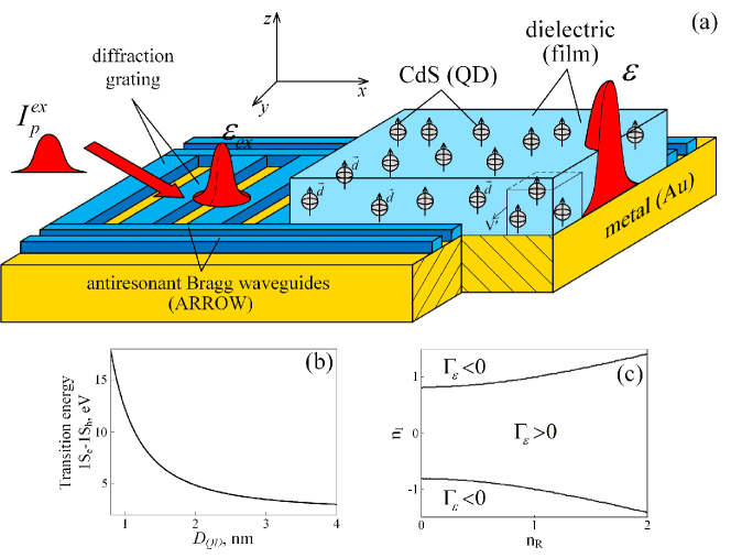
Consider the model of an interface in Fig. 1a in the form of a metal/dielectric waveguide MacDonald et al. (2009) with two-level chromophores located inside a thin dielectric layer, the transition frequency between the two levels being resonant with the plasmon frequency of the metal. By selecting a dielectric medium with appropriate dispersion characteristics and providing the initial excitation (inversion) of a dense ensemble of chromophores in this model, it is possible to produce the collective decay of excitons. The difference of this situation from the model of an emitting spaser van Beijnum et al. (2013) is that the dipole moments of chromophores are oriented in the direction perpendicular to the waveguide plane, which leads to the coherent transfer of their energy predominantly to SPP modes propagating along the xaxis. In this case, the process can be localized in the y direction using the system of additional waveguides operating based on the Bragg reflection of SPP (antiresonant-reflecting optical waveguide, ARROW Reinhardt et al. (2013)).
By considering the problem in the 3-D approximation, we assume that the characteristic size of the interaction region of the effective field of plasmons and chromophores satisfies the inequality and the inequality is also valid, where is the plasmon decay length along the axis. In this case, the time-dependent perturbation of the electron density appearing in the region in the metal causes induced processes in chromophores located in the symmetric region in the dielectric. Then, assuming that SPP modes are quasistatic within the volume under study Stockman et al. (2001), the corresponding Rabi frequencies can be written in the form , where , is the plasmon amplitude, is the transition dipole moment in a chromophore, and is the scalar potential of the plasmon field linearly decreasing with distance from the surface, is the Planck’s constant. In the case of excitation of a mode of the plasmon field at frequency , using the normalization Stockman et al. (2001), the expression for the Rabi frequency can be approximated by the function
where and is the number of plasmons in the interaction region.
For a metal-dielectric boundary, the relation
is valid, where the parameters and are the dielectric permittivities of dielectric (with QD) and metal, respectively. Here, is the plasma frequency in a metal, and are the electron mass and concentration, respectively, is the collision frequency in the metal, . The spectral properties of the metal-dielectric interface can be described by use of the Bergman’s parameter Stockman (2010).
We assume that the pumping volume is a dielectric containing QDs with the characteristic radius and concentration . The condition allows us to remain within the dipole approximation, but the large value of dipole transition moments of QDs Muller et al. (2004) requires the consideration of a local field acting on emitters Kuznetsov et al. (2011); Anikushina et al. (2015). At the same time, the effects of exchange dipole-dipole interaction Pokutnii (2006) between individual QDs, which are important in the superradiation problem of a localized spaser Braun et al. (2015), are neglected in our problem.
Assuming that the refractive index of the dielectric environment of QDs is a complex quantity, where and is the complex permittivity, expressions for the radiative relaxation rate , the Rabi frequency , and the effective frequency detuning can be written in the form Yu. Gubin et al. (2015a)
| (1a) | |||||
| (1b) | |||||
| (1c) | |||||
where is a complex function for which , ; and is a small correction caused by the Lamb shift. It is assumed here that the function coupling the Lorentz local and Maxwell fields will retain its structure in the case of the near field through which plasmons are excited in the scheme in Fig. 1.
The parameter is the total rate of radiative (with the time ) and nonradiative (with the time ) losses for QDs in vacuum. By using annealing technology Jae Ik Kim et al. (2012), the time can be increased to values comparable to the radiative time Sadhu and Patra (2008). At the same time, when a dense (more than ) ensemble of chromophores is located near the metal boundary, the spontaneous emission rate can considerably change and, in particular, increase Larkin et al. (2004); Sokolov et al. (2011). Note that the problem of temporal stability of single QDs during collective energy transfer to SPP in the configuration in Fig. 1a remains open, similarly to the blinking problem of emitting QDs Shchukina et al. (2015).
In the semiclassical approximation, the system can be described similarly to the metal nanoparticle in a dielectric with chromophores spaser model Stockman (2010) with the help of equations for elements of the density matrix of a two-level chromophore:
| (2a) | |||||
| (2b) | |||||
where , . The Rabi frequency can be written as , where is the coupling constant and is the normalized field with the amplitude of the total field produced by the perturbed electron density in a metal and the electromagnetic field component in a dielectric. In the general case, the relation between these components can be found only during the simultaneous solution of the evolution equation for the electron density in a conductor with the specified geometry and Maxwell’s equation Zabolotskii (2012).
The parameter in (2) determines the addition to the Rabi frequency appearing due to transition from the Maxwell to the local field Yu. Gubin et al. (2015a) acting on a chromophore.
The dispersion and dissipative corrections and , respectively, are expressed in terms of the real and imaginary parts of the permittivity of the host-medium Yu. Gubin et al. (2015a) in which QDs are placed and have the physical meaning of the additional frequency modulation and the effects of absorption () or amplification ( ) due to the local field (Fig. 2).
To pass to a self-consistent problem, system (2) should be supplemented with the equation of motion for the Rabi frequency of SPP, which in the case of the exact plasmon resonance has the form
| (3) |
where
determines the characteristic formation time for quantum correlations in the chosen volume in Fig. 1a (compare with the optical problem Benedict and Trifonov (1988) when emitters are located in the field formation region).
Note that the plasmon mode decay rate is high and determined by the characteristic times and of radiative and joule losses, respectively. Under conditions Dorofeenko et al. (2012), radiative losses can be neglected, while joule losses are determined by the collision frequency in a metal, i.e., , and in problem (3) in the absence of pump , the shortrange SPP appear. In the presence of the maximum of a surface wave energy in the metal, the self-consistent problem (2)–(3) will be valid only under conditions when the characteristic establishment time for correlations between plasmons proves to be considerably shorter than . Because is inversely proportional to the dipole moment of a chromophore, the relation can be valid for pumping a distributed waveguide spaser by QDs with their giant dipole transition moments.
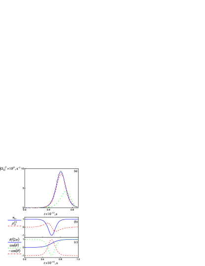
In a simple case and in the absence of external excitation , the collective behavior of the system, in particular, excitation of superradiation, as in an optical scheme, is stimulated by a small initial polarization of the system initiating the growth of the real part of the Rabi frequency according to the relation (see (3)). Thus, the front wing of a surface electromagnetic pulse (SPP pulse) will be formed. Then, according to from (2a) and under the condition , the growth of is observed (Fig. 2b), which leads to the excited-level decay according to
from (2b). The process will also continue with the beginning of saturation in the system. However, because of the change in the sign of the population difference , the parameter gradually decreases to zero. The condition is fulfilled at characteristic times (where and is the number of chromophores in the interaction region Benedict et al. (1996)) when a plasmon pulse is formed. Then this process is repeated but already in the region where the parameter is negative, which leads to the formation of the rear edge of the pulse (Fig. 2). A similar picture is also observed in the case of a low initial stochastic coherence of the system in Zaitsev et al. (1999).
The use of QDs for pumping with their giant dipole moments at the operating transition can result in a significant shortening of the establishment time for quantum correlations and in the proportional decrease in the delay time and duration of SPP pulses generated in the system. As a model medium, we use CdS QDs Baskoutas and Terzis (2006) located in a dielectric film near the gold surface. Taking into account the plasmon frequency of gold and choosing the condition , the wavelength of generated SPP is . To determine the QD size in the case of the exact resonance , we use the known dependence Bel Haj Mohamed et al. (2014) of the transition energy on the QD diameter (Fig. 1b)
| (4) |
where is the electron charge, and are the effective electron and hole masses, respectively, in the volume of the QD material with the permittivity and band gap energy Milekhin et al. (2002); Guerrero (2013). The corresponding parameters for CdS are , and Pokutnii (2006), which gives . Bohr radius of exciton for CdS is Pokutnii (2010) therefore strong confinement regime Fedorov and Baranov (2005) will be observed for the considered QDs, and energy sublevels of conductivity zone will be essentially separated. To tune the QD size to the plasmon resonance more accurately, it is useful to employ experimental curves for particular synthesized QDs Kozhevnikova et al. (2015). The dipole moment of the corresponding interband transition in QDs is assumed equal to Stockman (2010).
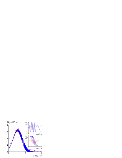
For chosen model parameters and the QD concentration , the characteristic correlation time is and the delay time for the number of chromophores in the interaction region . The duration of a formed SPP monopulse is only about ; for regime 1 in Fig. 2 taking into account the uncompensated rate of radiative losses, for QDs near the metal surface Larkin et al. (2004). The additional consideration of the decay rate of plasmons in gold even under the condition does not strongly affect on the development of the formation dynamics of the plasmon pulse (regime 3 in Fig. 2a).
However, taking (1a) into account, the choice of the appropriate dielectric host-medium can partially or completely compensate the increase of (Fig. 1c), but it is also obvious that the properties of natural media are strongly restricted. Thus, for silica at the wavelength under study , we have , Kitamura et al. (2007) and . To completely compensate relaxation processes in (2a) (), the required combination of dispersion-dissipative parameters should satisfy the condition (be neglecting a small Lamb shift), which is satisfied, for example, for the choice and . Such conditions can be fulfilled for an artificial microstructured dielectric material with specified dispersion dissipative characteristics (the Cole-Cole diagram). They lead to the significant increase in the SPP pulse intensity, while energy transfer from chromophores to radiation proves to be suppressed (see regime 2 in Fig. 2a). In this case, the influence of the local field increases, the absolute values of its parameters increase (corrections and in (2)) and the formation dynamics of SPP pulses changes.
III Collective dynamics of a waveguide spaser in the mean field approximation
To analyze the contribution of dissipative effects related to the imaginary part of the local field correction, we can neglect the corresponding phase effects with in (2) and decay in (2)–(3) and to pass in the mean field approximation to a simplified system of self-consistent equations for a medium
| (5a) | |||||
| (5b) | |||||
and the effective field
| (6) |
formed in it.
By passing to the representation for the Rabi frequency and polarization in the form
where , and assuming that , we can obtain the system of Maxwell-Bloch equations for a spaser taking into account the (dissipative) local response of the QD environment
| (7a) | |||||
| (7b) | |||||
| (7c) | |||||
The system of equations (7) was derived using the rotating wave approximation by neglecting high-frequency terms with phase factors . By passing to new dimensionless variables and , where and setting and , we represent system (7) in the form
| (8a) | |||||
| (8b) | |||||
| (8c) | |||||
The solution of system (8) can be written in the form and , where and determine the amplitude and angle of the so-called Bloch vector with coordinates and and their substitution to (8) gives the equation for the angle
| (9) |
By substituting the expression for from (9) into (8c), we obtain a new variant of the pendulum equation with the nonlinear harmonic losses/decay term
| (10) |
The second term in the left-hand side of (10) is responsible for processes initiated by the local response of the medium and synchronized with the change in the angle . By using the separatrix condition corresponding to the passage from the rotational motion of the pendulum to vibrational, Eq. (10) can be written in the form
| (11) |
where the amplitude of the decay coefficient is defined as . In the absence of the loss modulation, when , Eq. (11) is reduced to the usual nonlinear pendulum equation with losses Benedict et al. (1996). Taking the modulation into account under the same conditions ( and ), the pendulum experiences the additional decay in intervals
responsible for the formation of the leading and trailing edges of SPP pulse (see Fig. 2c), whereas in the interval
when the central part of SPP pulse is formed, the enhancement of pendulum oscillations is observed; .
In other words, the absorbing dielectric host-medium coherently preserves a part of the QD energy during the formation of the leading edge of the pulse and then coherently returns this energy to SPP pulse during formation of the pulse peak. As a result, taking into account the compensation of the spontaneous relaxation rate of QDs () and nonlinear terms with in (5), the increase in the peak pulse intensity is observed with respect to the case when the response of the host-medium is neglected (see Fig. 2a).
It seems that in the presence of strong resonator effects in the dielectric host-medium near the QD resonant wavelength, the peak intensity of generated pulses can be additionally increased due to terms with and in system (2). But because these corrections are obtained assuming that the spasing wavelength lies at the wing of the absorption line of a dielectric film Yu. Gubin et al. (2015a), this theory cannot be applied to the given case. Nevertheless, such amplification can be achieved, for example, using dielectric metamaterials Shcherbakov et al. (2014) with a specially selected geometry doped with QDs Krishnamoorthy et al. (2012); McEnery et al. (2014); Yu. Gubin et al. (2015b). In this case, it is possible to excite longrange surface plasmon polaritons Konopsky and Alieva (2006) at a metal/(QDdoped metamaterial) boundary with their simultaneous amplification due to QD pumping. However, problem (2)–(3) becomes considerably complicated in this case, because of the necessity of describing the field components in a dielectric, the consideration of the geometry of individual scattering centers Pavlov et al. (2013) and the influence of the inhomogeneous structured microenvironment on the spontaneous decay rate in QDs Klimov et al. (2015).
For the case () Yu. Gubin et al. (2015a), when a host-medium with the background amplification exists, on the contrary, energy transfer from the medium to emitters doped into it should occur in the initial stage of the plasmon pulse formation. This causes the advance of the pulse generation in the medium and a partial loss in the pulse intensity compared to the case .
In the known case , the separatrix solution of Eq. (11) has the form , where the dimensionless delay time is with the initial angle . This corresponds to the formation of a monopulse with the Rabi frequency modulus squared that can be written in the form
| (12) |
at the real time scale (regime 1 in Fig. 2a).
To simulate Eqs. (5)–(11), we considered a particular regime assuming that the plasmon phase is . In this case, as considered in Section II, the initial polarization of the system is only imaginary and the Rabi frequency can be written as , where the expansion is used. Under such conditions, the only real part of the Rabi frequency of the pulse is formed and system (8) is transformed to the system
| (13a) | |||||
| (13b) | |||||
| (13c) | |||||
However, the form of Eq. (11), to which (13) is reduced, does not change under the new normalization condition . The initial conditions in simulation of (11) are chosen equal to for the initial oscillation angle and
for the initial velocity of the pendulum.
Equation (11) is a particular case of the Lienard equation and its approximate analytic solution can be expressed in terms of elliptic integrals of the first kind. The numerical solution for the Rabi frequency of SPP pulse field obtained from (11) completely coincides with the results of the direct numerical simulation of system (5)–(6) under conditions of the suppression of spontaneous relaxation in QDs for the chosen values and () (see regime 2 in Fig. 2a).
IV Influence of concentration and dissipative effects on the development of collective regimes of a waveguide spaser
The solutions of Eq. (11) are obtained under conditions of the suppression of spontaneous emission of excited QDs near a metal/dielectric boundary, whereas the violation of relations obtained for parameters and should lead to the increase in the rate of relaxation processes and the weakening of SPP pulses. In this case, the efficiency of the QD energy transfer to the superradition mode nonlinearly depends on the parameter characterizing the relative deviation of the loss coefficient of the host-medium from the specified level for which the condition is exactly fulfilled for fixed (see Fig. 3a). In particular, the decrease in leads to the increase in the relaxation rate and the related decrease in the area
of SPP pulses presented in Fig. 3b and calculated by direct numerical simulation of system (2)–(3).
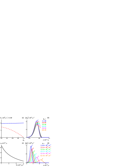
On the other hand, the change in the QD concentration under the condition in the system, allows one to control the delay time and pulse duration at the medium output. Thus, the increase in the QD concentration for CdS leads to the rapid nonlinear shortening of the delay time in the model under study (Fig. 3c) with the emission more and more intense pulses (Fig. 3d).
To analyze nonlinear phase effects during the generation of plasmon pulses, it is necessary to take into account the spatial dynamics of collective processes by introducing the longitudinal coordinate into Eq. (3). The corresponding solution at the output of a medium of length with the isotropic distributions of chromophores will have the form Benedict and Trifonov (1988)
| (14) | |||||
where is determined by the new characteristic formation time of quantum correlations, is the amplitude of an additional trigger SPP pulse at the entrance of waveguide, and the factor gives phase shifts which, unlike the case considered in Section III, depend on the coordinate .
It is convenient to study the influence of nonlinear dispersion effects on the spectral features of SPP pulses beginning from the numerical solution of the joint system of equations (2) and (14) under conditions when a trigger pulse at the medium input is absent and also by neglecting dissipative terms of the local field .
The real spectral shape of pulses generated in such approximation is determined by the inverse Fourier transform from the corresponding Rabi frequency at the medium output
| (15) | |||||
In a simple case in the absence of the frequency modulation and neglecting delay effects, the full width at half maximum of a spectrally limited pulse is determined only by its duration . For a pulse in the form of a hyperbolic secant (12), the relation is valid, where Akhmanov et al. (1988).
Figures 4a,b show that the spontaneous relaxation is suppressed rate (, ) but the effective frequency detuning is simultaneously formed in the system (see (1c)) corresponding to the appearance of linear dispersion. It leads, according to (14), to the formation of dispersion delays and the appearance of characteristic oscillations of the parameter (and also of ) at frequency . The relation between the spectral width and duration of such a modulated pulse changes to , where (see Figs.4a, 4b). However, nonlinear phase effects corresponding to the contribute of terms with into (2a) were neglected in Figs. 4a, 4b.

On the other hand, the consideration of only nonlinear terms in (2a) in the absence of linear dispersion () leads to a strong nonlinear frequency modulation of the parameter , which, according to (14) is superimposed on the profile of a generated plasmon pulse. The specific feature of such a modulation is manifested in the change of its sign with displacement from the wing of SPP pulse, where , to its peak, where , and in the formation of the characteristic profile of the imaginary component of the Rabi frequency (see the inset in Fig. 4c for arbitrarily chosen ).
Under model conditions, for the chosen values and , the calculated value of will be and the effects of linear and nonlinear dispersion will act simultaneously. As a result, a mixed regime with the phase modulation rate nonlinearly increasing from the pulse front to its tail appears in the system (see Fig. 4c). The relation between the duration of such a modulated pulse and its spectral width takes the form , where , and its spectrum significantly broadens, becoming in fact rectangular (Fig. 4d). This result obtained for a distributed waveguide spaser in a pulsed regime considerably differs from the case of localized spaser with the characteristic spectral narrowing effect Andrianov et al. (2013). The spectral broadening regime for SPP pulse for the interface presented in Fig. 1 can find new applications in the problems of the development of broadband electromagnetic sources Xiao Tao Geng et al. (2016), similarly to the generation of laser combs in optics Levy et al. (2010).
V Features of the triggered regime of a waveguide spaser
The feature of the triggered regime in the scheme in Fig. 1a, similarly to triggered optical superradiation (TSR), is related to the possibility of controlling the development of cooperative process in a system when the establishment of quantum correlations between individual chromophores is initiated by the external pump pulse. In this case, the development dynamics, the radiation pattern and the shape of a supperradiation pulse are completely determined by the parameters of this trigger pulse. In optics, such a regime was first observed in gas medium in Vrehen and Schuurmans (1979). However, only the realization of this effect in solids Zinoviev et al. (2001) provided the basis for using TSR for the development of optical memory and optical computing devices Andrianov and Samartsev (1998). The translation of this problem to plasmonics offers a number of advantages, retaining, on the one hand, optical data processing rates and, on the other hand, considerably simplifying the integration of individual plasmonic devices in circuits and providing their coupling with electronic computing devices.
In the problem (2)–(4), the triggered regime of generation of plasmon pulses can be achieved in the presence of a trigger SPP pulse
| (16) |
with duration and time delay () with respect to the beginning of the free evolution of the system due to a relaxation process (see Section II). The trigger pulse can be obtained by transforming an external optical pulse on a metal grating, as in Sobhani et al. (2013) (Fig. 1a). As in the optical case, the specific feature of the regime is the possibility of controlling the delay time of the main SPP pulse Kalinkin et al. (2002), which in the classical formulation of the problem by neglecting local field effects is determined by the expression
| (17) |
and depends on the trigger pulse area
In this case, the amplitude of the optical trigger pulse can be recalculated to parameters (16) according to the relation
for the ideal case when of the optical pulse energy transfer to a surface wave.
Figure 5a presents the results of simulating system (2) + (14) in the form of a set of the time dependences of the Rabi frequencies of main pulses produced under the action of input trigger pulses with different areas with increasing their peak intensity , where . The corresponding dependences for the delay times of SPP pulse formation are also approximated by expression (17) taking into account that recalculation expressions between the normalized time and the real time are analogous to the passage from system (7) to (8). For the chosen combination of the QD concentration, the duration and power of trigger pulses, the profile of the main formed pulse in Fig. 5a remains virtually invariable.
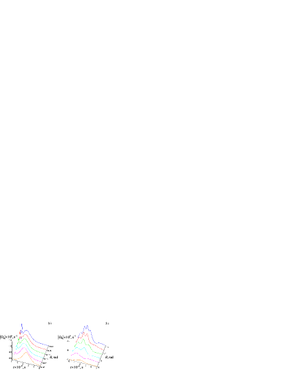
The regime will qualitatively change when the trigger pulse duration (16) becomes close to the characteristic duration of the main SPP pulse (transition regime) and its delay is selected so that its envelope partially or completely overlaps the envelope of the generated pulse. Under such conditions, the field intensity at the medium output can exhibit a multipeak structure (see Figs. 5b and 6).
A similar superradiation regime is well known in optics and is caused by the nonmonotonic decay of the excited state of continuous media Basharov et al. (2006). However, in the case under study for and , the effect is caused by modulation instabilities in the process of QDs excitons decay resulting in the appearance of Rabi oscillations (see the upper inset in Fig. 6) neglecting dispersion effects with .
When nonzero frequency detunings are taken into account in system (2), the time synchronization of oscillations of the polarization component and the population difference is violated. As a result, the amplitude of oscillations appearing in the system is modulated by a decreasing function of time proportional to the inverse detuning frequency (see the lower inset in Fig. 6) in the approximation .
The consideration of the influence of a dielectric host-medium with the dispersion coefficient again leads to a strong nonlinear frequency modulation of the produced pulse (similarly to Figs. 4c, 4d). However, in the case of its interference with trigger pulse (16) with appropriate duration (as in Fig. 5b), the envelope of the resulting pulse acquires a strong high-frequency amplitude modulation, which is absent for in Fig. 6. The spectra and envelope shape of the SPP pulse can be recorded by performing the inverse transformation of surface waves to an optical signal on a metal grating [29]. Note that a noticeable change in the permittivity of a metal due to optical excitation of electrons is observed at the energy density on the order of Pohl et al. (2012). This allows one to realize pure plasmon nonlinearities MacDonald et al. (2009) and perform direct signal-pump experiments with surface plasmon-polaritons. However, after conversion to dimensional parameters, the energy density of emitted pulses in Fig. 5 does not exceed and therefore conditions for these nonlinear regimes are not achieved in this work.
It is necessary to note, that the contribution of dissipative effects of the local field to problem (2) can be estimated as
where
and for , we have . Similarly, we can obtain the estimate for the dispersion coefficient
determining the relative contribution of local field effects to the frequency modulation of the produced signal. Thus, the contribution of local field effects to the kinematics of the system under study depends only on the introduced coefficients and determined only by the material parameters of the host-medium, but not by its geometry.
VI Conclusions
We have proposed new efficient methods for the formation and external control of short SPP pulses at the interface of a metal and a QD-doped dielectric medium. The conditions for selecting parameters of QDs and a dielectric host-medium are determined which provide the maximal collective energy transfer from a QD ensemble to SPP modes dominating over the radiative relaxation of individual chromophores. By the example of a model medium with CdS nanocrystals, the dimensional and concentration dependences of the effect are studied and the amplitude and spectral features of SPP pulses generated in the system are determined. The presented model and studied regimes can be used, in particular, for solving a practical problem of increasing the characteristic coherent lengths of the SPP field.
Our approach can be realized in experiments by using dielectric films doped with semiconductor QDs with diameters selected to provide the equality of energies of interband transition and plasmons excited at the metal-dielectric interface. However, it is necessary to take into account that the efficiency of energy transfer from excitons to plasmon modes can be affected by blinking, as in the case of luminescent QDs Shchukina et al. (2015). In addition, the physical characteristics of QDs significantly differ from perfect and strongly depend on the method of their synthesis and characteristics of the host-medium Magaryan et al. (2016). In this case, the use of organic molecules can serve as an alternative for interface pumping (Fig. 1) Naumov (2013).
The models presented in the paper can be useful for practical applications such as the development of plsamonic integrated circuits for quantum computations. In particular, considerated collective effects can be used as a basis for multiqubits register initialization in the process of formation the quantum correlations between QD. The advantage of the realization of such a register in the plasmon-exciton systems to atomic-optical systems is the ability to implement an effective addressing schemes by coupling of each quantum dot with localized plasmon modes on the nanoscale. However, this requires complication of the circuit shown in Fig. 1. Besides, important problems of the direct connection of such systems with all-optical data communication systems remain open. In particular, one of the problems is increasing the efficiency of mutually reversible conversion of the light wave field and plasmon polaritons formed in layered structures Bermudez-Urena et al. (2015). Final answers to these problems can be obtained in relevant experiments, in particular, using epiluminescence spectromicroscopy of single quantum emitters Naumov et al. (2009, 2011, 2014).
Another important technical problem is achieving very high QD concentrations in a matrix which for the maximum concentration used in this paper (Fig. 3c) will amount to of the concentration of the closest packing of QDs with diameter . One of the solutions can be using the self-organization of QDs with different sizes during their evaporation from colloid solutions Adrianov et al. (2011) on a substrate. However, the prospects for using such structures under conditions of the problem under study require special studies due to a considerable dispersion of QDs in size.
Note in conclusion that it is also important to obtain a more general nonlinear equation describing the propagation of ultrashort SPP pulses in experiments taking into account nonstationary terms of the nonlinear dispersion type, etc. Zabolotskii (2012); Lemke et al. (2013). Such terms can appear due to modification of the metal permittivity by high-power pump femtosecond pulses of an external optical pump MacDonald et al. (2009) and due to nonlinear effects in semiconductor QDs Yu. Perlin and Fedorov (1995) and in a dielectric host-medium containing them Xue et al. (2014). Such an equation can serve as a starting point for searching and determining the stability conditions Prokhorov et al. (2012) for its soliton solutions and the development of new schemes of active nanoplasmonics Khokhlov et al. (2014) with dissipative SPP solitons.
VII Acknowledgments
One of the authors (A.V.P) thanks A.B. Evlukhin for useful discussions. The work was supported by the Russian Foundation for Basic Research (project nos. 14-02-97511, 14-29-07270 ofi m) and the Ministry of Education and Science of the Russian Federation (task VLSU no. 2014/13).
References
- Skribanowitz et al. (1973) N. Skribanowitz, I. P. Herman, J. C. MacGillivray, and et al., Phys. Rev. Lett. 30, 309 (1973).
- Andreev et al. (1980) A. V. Andreev, V. I. Emel’yanov, and Yu. A. Il’inskii, Sov. Phys. Usp. 23, 493 (1980).
- Florian et al. (1982) R. Florian, L. O. Schwan, and D. Schmid, Solid State Commun. 42, 55 (1982).
- Zinov’ev et al. (1983) P. V. Zinov’ev, S. V. Lopina, Yu. V. Naboikina, and et al., Sov. Phys. JETP 58, 1129 (1983).
- Stockman (2010) M. I. Stockman, J. Opt. 12, 024004 (2010).
- Vinogradov et al. (2012) A. P. Vinogradov, E. S. Andrianov, A. A. Pukhov, A. V. Dorofeenko, and A. A. Lisyansky, Phys. Usp. 55, 1046 (2012).
- Lambright et al. (2014) S. Lambright, E. Butaeva, N. Razgoniaeva, and et al., ASC Nano 8, 352 (2014).
- Protsenko and Uskov (2015) I. E. Protsenko and A. V. Uskov, Quantum Electron. 45, 561 (2015).
- Fedorov et al. (2015) S. V. Fedorov, N. N. Rosanov, A. V. Chipouline, and et al., J. Opt. Soc. Am. B 32, 824 (2015).
- Dorofeenko et al. (2012) A. V. Dorofeenko, A. A. Zyablovsky, A. P. Vinogradov, and et al., Opt. Express 21, 14539 (2012).
- van Beijnum et al. (2013) F. van Beijnum, P. J. van Veldhoven, and E. J. Geluk, Phys. Rev. Lett. 110, 206802 (2013).
- Braun et al. (2015) K. Braun, X. Wang, A. M. Kern, and et al., Beilstein J. Nanotechnol. 6, 1100 (2015).
- Lisyansky et al. (2011) A. Lisyansky, I. Nechepurenko, A. Dorofeenko, and et al., Phys. Rev. B 84, 153409 (2011).
- Martín-Cano et al. (2010) D. Martín-Cano, L. Martín-Moreno, F. J. García-Vidal, and et al., Nano Lett. 10, 3129 (2010).
- Kress et al. (2015) S. J. Kress, F. V. Antolinez, P. Richner, and et al., Nano Lett. 15, 6267 (2015).
- Reinhardt et al. (2013) C. Reinhardt, A. B. Evlyukhin, W. Cheng, and et al., J. Opt. Soc. Am. B 30, 2898 (2013).
- Konopsky and Alieva (2006) V. N. Konopsky and E. V. Alieva, Phys. Rev. Lett. 97, 253904 (2006).
- Choquette et al. (2010) J. J. Choquette, K.-P. Marzlin, and B. C. Sanders, Phys. Rev. A 82, 023827 (2010).
- Zabolotskii (2011) A. A. Zabolotskii, J. Exp. Theor. Phys. 112, 642 (2011).
- Zabolotskii (2012) A. A. Zabolotskii, J. Exp. Theor. Phys. 114, 699 (2012).
- Stockman (2011) M. I. Stockman, Phil. Trans. R. Soc. A 369, 3510 (2011).
- Larkin et al. (2004) I. A. Larkin, M. I. Stockman, M. Achermann, and et al., Phys. Rev. B 69, 121403 (2004).
- Kuraptsev and Sokolov (2014) A. S. Kuraptsev and I. M. Sokolov, Phys. Rev. A 90, 012511 (2014).
- Sokolov et al. (2011) I. M. Sokolov, D. V. Kupriyanov, and M. D. Havey, J. Exp. Theor. Phys. 112, 246 (2011).
- Golovanova et al. (2016) A. V. Golovanova, M. Yu. Gubin, M. G. Gladush, and A. V. Prokhorov, Bull. Russ. Acad. Sci. Phys. 80, 808 (2016).
- Hopf et al. (1984) F. A. Hopf, C. M. Bowden, and W. H. Louisell, Phys. Rev. A 29, 2591 (1984).
- Kuznetsov et al. (2011) D. V. Kuznetsov, M. G. Gladush, and V. K. Roerikh, J. Exp. Theor. Phys. 113, 647 (2011).
- Anikushina et al. (2015) T. A. Anikushina, M. G. Gladush, A. A. Gorshelev, and et al., Faraday Discuss. 184, 263 (2015).
- MacDonald et al. (2009) K. F. MacDonald, Z. L. Sarmson, M. I. Stockman, and et al., Nat. Photon. 3, 55 (2009).
- Stockman et al. (2001) M. I. Stockman, S. V. Faleev, and D. J. Bergman, Phys. Rev. Lett. 87, 167401 (2001).
- Muller et al. (2004) A. Muller, Q. Q. Wang, P. Bianucci, and et al., Appl. Phys. Lett. 84, 981 (2004).
- Pokutnii (2006) S. I. Pokutnii, Semiconductors 40, 217 (2006).
- Yu. Gubin et al. (2015a) M. Yu. Gubin, A. Yu. Leksin, M. G. Gladush, S. M. Arakelian, and A. V. Prokhorov, Opt. Spectrosc. 119, 497 (2015a).
- Jae Ik Kim et al. (2012) Jae Ik Kim, Jongmin Kim, Junhee Lee, and et al., Nanoscale Res. Lett. 7, 482 (2012).
- Sadhu and Patra (2008) S. Sadhu and A. Patra, Chem. Phys. Chem. 9, 2052 (2008).
- Shchukina et al. (2015) A. L. Shchukina, I. Y. Eremchev, and A. V. Naumov, Phys. Rev. E 92, 032102 (2015).
- Benedict and Trifonov (1988) M. G. Benedict and E. D. Trifonov, Phys. Rev. A 38, 2854 (1988).
- Benedict et al. (1996) M. G. Benedict, A. M. Ermolaev, and V. A. Malyshev, Superradiance. Multiatomic Coherent Emission (IOP, Philadelphia, USA, 1996).
- Zaitsev et al. (1999) A. I. Zaitsev, V. A. Malyshev, I. V. Ryzhov, and et al., J. Exp. Theor. Phys. 88, 278 (1999).
- Baskoutas and Terzis (2006) S. Baskoutas and A. F. Terzis, J. Appl. Phys. 99, 013708 (2006).
- Bel Haj Mohamed et al. (2014) N. Bel Haj Mohamed, M. Haouari, Z. Zaaboub, and et al., J. Nanopart. Res. 16, 2242 (2014).
- Milekhin et al. (2002) A. G. Milekhin, L. L. Sveshnikova, S. M. Repinskii, A. K. Gutakovskii, M. Friedrich, and D. R. T. Zahn, Phys. Solid State 44, 1976 (2002).
- Guerrero (2013) S. I. C. Guerrero, Doctoral thesis (micro nanotechnol., acoust., telecommun.), Lille, France (2013).
- Pokutnii (2010) S. I. Pokutnii, Semiconductors 44, 488 (2010).
- Fedorov and Baranov (2005) A. V. Fedorov and A. V. Baranov, Optics of quantum dots. In Proc. Optics of nanostructures., edited by A. V. Fedorov (Nedra, SPb., 2005).
- Kozhevnikova et al. (2015) N. S. Kozhevnikova, A. S. Vorokh, and A. A. Uritskaya, Russ. Chem. Rev. 84, 225 (2015).
- Kitamura et al. (2007) R. Kitamura, L. Pilon, and M. Jonasz, Appl. Opt. 46, 8118 (2007).
- Shcherbakov et al. (2014) M. R. Shcherbakov, D. N. Neshev, B. Hopkins, and et al., Nano Lett. 14, 6488 (2014).
- Krishnamoorthy et al. (2012) H. N. S. Krishnamoorthy, Z. Jacob, E. Narimanov, and et al., Science 336, 205 (2012).
- McEnery et al. (2014) K. R. McEnery, M. S. Tame, S. A. Maier, and et al., Phys. Rev. A 89, 013822 (2014).
- Yu. Gubin et al. (2015b) M. Yu. Gubin, A. V. Pishenko, S. M. Arakelian, and et al., Phys. Proc. 73, 7 (2015b).
- Pavlov et al. (2013) A. A. Pavlov, V. V. Klimov, Y. V. Vladimirova, and et al., Quantum Electron. 43, 496 (2013).
- Klimov et al. (2015) V. V. Klimov, D. V. Guzatov, and I. V. Treshin, Phys. Rev. A 91, 023834 (2015).
- Akhmanov et al. (1988) S. A. Akhmanov, V. A. Vysloukh, and A. S. Chirkin, The Optics of Femtosecond Pulses (Nauka, Moscow, 1988) in Russian.
- Andrianov et al. (2013) E. S. Andrianov, A. A. Pukhov, A. V. Dorofeenko, A. P. Vinogradov, and A. A. Lisyansky, J. Exp. Theor. Phys. 117, 205 (2013).
- Xiao Tao Geng et al. (2016) Xiao Tao Geng, Byung Jae Chun, Ji Hoon Seo, and et al., Nat. Commun. 7, 10685 (2016).
- Levy et al. (2010) J. S. Levy, A. Gondarenko, M. A. Foster, and et al., Nat. Photon. 4, 37 (2010).
- Vrehen and Schuurmans (1979) Q. H. F. Vrehen and M. F. H. Schuurmans, Phys. Rev. Lett. 42, 224 (1979).
- Zinoviev et al. (2001) P. V. Zinoviev, V. A. Zuikov, A. A. Kalachev, and et al., Laser Phys. 11, 1307 (2001).
- Andrianov and Samartsev (1998) S. N. Andrianov and V. V. Samartsev, Laser Phys. 8, 1194 (1998).
- Sobhani et al. (2013) A. Sobhani, M. W. Knight, Yu. Wang, and et al., Nat. Commun. 4, 1643 (2013).
- Kalinkin et al. (2002) A. A. Kalinkin, A. A. Kalachev, and V. V. Samartsev, Teor. Fiz. 3, 87 (2002).
- Basharov et al. (2006) A. M. Basharov, G. G. Grigoryan, N. V. Znamenskii, E. A. Manykin, Yu. V. Orlov, A. Yu. Shashkov, and T. G. Yukina, J. Exp. Theor. Phys. 102, 206 (2006).
- Pohl et al. (2012) M. Pohl, V. I. Belotelov, I. A. Akimov, and et al., Phys. Rev. B 85, 081401 (2012).
- Magaryan et al. (2016) K. A. Magaryan, M. A. Mikhailov, K. R. Karimullin, and et al., J. Lumin. B 169, 799 (2016).
- Naumov (2013) A. V. Naumov, Phys. Usp. 56, 605 (2013).
- Bermudez-Urena et al. (2015) E. Bermudez-Urena, C. Gonzalez-Ballestero, M. Geiselmann, and et al., Nat. Commun. 6, 7883 (2015).
- Naumov et al. (2009) A. V. Naumov, A. A. Gorshelev, Y. G. Vainer, and et al., Angew. Chem. 48, 9747 (2009).
- Naumov et al. (2011) A. V. Naumov, A. A. Gorshelev, Y. G. Vainer, and et al., Phys. Chem. Chem. Phys. 13, 1734 (2011).
- Naumov et al. (2014) A. V. Naumov, I. Y. Eremchev, and A. A. Gorshelev, Eur. Phys. J. D 68, 348 (2014).
- Adrianov et al. (2011) V. E. Adrianov, V. G. Maslov, A. V. Baranov, and et al., Opt. Zh. 78, 11 (2011).
- Lemke et al. (2013) C. Lemke, C. Schneider, T. Leißner, and et al., Nano Lett. 13, 1053 (2013).
- Yu. Perlin and Fedorov (1995) E. Yu. Perlin and A. V. Fedorov, Opt. Spectrosc. 78, 400 (1995).
- Xue et al. (2014) Y. Xue, F.-w. Ye, D. Mihalache, and et al., Laser Photon. Rev. 8, 52 (2014).
- Prokhorov et al. (2012) A. V. Prokhorov, M. Yu. Gubin, A. Yu. Leksin, M. G. Gladush, A. P. Alodzhants, and S. M. Arakelyan, J. Exp. Theor. Phys. 115, 1 (2012).
- Khokhlov et al. (2014) N. E. Khokhlov, D. O. Ignatyeva, and V. I. Belotelov, Opt. Express 22, 28019 (2014).