Channeling and radiation of the MeV electrons enhanced by the re-channeling in a periodically bent diamond crystal
Abstract
Channeling properties and radiation spectra are studied on the grounds of numerical simulations for the MeV electrons in a periodically bent diamond crystal. The bent crystalline profiles are shown to enhance the re-channeling of the projectiles and to produce distinct lines in the radiation spectra. The results obtained are analyzed and contrasted to the properties of the planar channeling and of the channeling in uniformly bent crystals.
pacs:
61.85.+pChanneling phenomena and 41.60.-mRadiation by moving charges and 41.75.HtRelativistic electron and positron beams and 02.70.UuApplications of Monte Carlo methods1 Introduction
Propagation of relativistic charged particles in oriented crystals remain for several decades in focus of challenging research. As predicted by Lindhard Lindhard1965 , the projectiles can channel in crystals moving along the crystalline planes or axes. The properties of channeling and the radiation produced by the projectiles have been receiving a significant interest, both with respect to a fundamental theory and the experiments, see, e.g., the book ChannelingBook2014 and the references therein.
In plane crystals, channeling enhances the radiation yield as compared to that produced by the non-channeling projectiles. The enhancement results from the inter-planar oscillations of the channeling projectiles and manifests itself in the radiation spectra at the energies determined by the oscillation frequencies and the projectile energies. The radiation from bent crystals displays additional features related to the bending. For example, the arc-bent crystals (also commonly referred to as uniformly bent), produce a synchrotron-type radiation at the energies dependent on the bending radius BentSilicon_2014 . A periodically bent crystal can work as a crystalline undulator (CU) causing modulations in the motion of the projectiles with the frequencies determined by the bending period. This can result in undulator lines in the radiation spectra, which is an attractive property of CUs as the sources of monochromatic radiation in a sub-MeV to MeV energy range KSG1998 ; KSG_review_1999 . A variety of experiments were performed to produce and detect the undulator radiation. The recent experimental studies as well as an outlook to the ongoing and future experiments can be found in, e.g, Refs. BadEms_p38 ; BadEms_p58 ; BadEms_p63 ; Wienands_Talk_2016 .
One can distinguish two basic types of periodical bending that lead to different relations between the frequencies of channeling and undulator oscillations of the projectiles. One is a large-amplitude long-period bending, originally suggested KSG1998 ; KSG_review_1999 for the crystalline undulator as a device where the channeling particles follow the periodically bent crystalline planes. There, the undulator modulation frequencies are smaller than the frequencies of the channeling oscillations, and the undulator spectral lines arise at the energies below the energies of the channeling lines. Another type is a small-amplitude short-period bending Kostyuk_PRL2013 which produces regular jitter-type modulations of the projectile motion with the period shorter than the period of the channeling oscillations. The corresponding lines arise in the radiation spectra at the energies exceeding the energies of the channeling peaks.
Channeling and radiation in the bent crystals have been extensively studied, to be mentioned among others is a series of works BentSilicon_2013 ; Sub_GeV_2013 ; Backe_EtAl_PRL2014 ; Multi_GeV_2014 ; Sushko_EtAl_NIMB_v355_p39_2015 ; Wistisen_EtAl_2016 ; Korol_EtAl_NIMB_v387_p41_2016 . The most frequently addressed, both theoretically and experimentally, are the silicon crystals. In the present work, we study the channeling and radiation in diamond, motivated by the current experiments at the MAinzer MIcrotron (MAMI) BadEms_p63 ; Backe_private . In relation with the experimental conditions, we perform numerical simulations on the propagation of the MeV electrons through the plane, uniformly bent and periodically bent diamond (110). We focus on a large-amplitude long-period CU, in particular, compute the radiation spectra for the bending amplitude larger than the distance Å between the (110) planes in the straight diamond. The simulations will show that the channeling electrons follow the bent planes and produce distinct undulator features in the radiation spectra. The results will also reveal an enhanced re-channeling process which develops in the periodically bent structures and makes them superior to the uniformly bent ones in supporting the channeling.
The theoretical framework of the simulations is described in detail in, e.g., Refs. ChannelingBook2014 ; ChanModuleMBN_2013 . We use the MBN Explorer package MBN_ExplorerPaper ; MBN_ExplorerSite to compute the motion of the ultra-relativistic projectiles through the crystals along with a dynamical simulation of the crystalline structures in the course of motion ChanModuleMBN_2013 . The computations account for the interaction of the projectiles with the separate atoms of the environments. We remark that, with a variety of implemented inter-atomic potentials, the MBN Explorer supports rigorous simulations of various environments, including crystalline, amorphous, and biological ones. The trajectories of the projectiles are used to compute the spectra of the emitted radiation. The simulation procedure is outlined in Section 2 and is followed by the studies of channeling properties (Section 3) and of radiation spectra (Section 4) for the diamond crystalline structures. The conclusions are given in Section 5.
2 Simulation procedure
For numerical studies we introduce a reference frame with the -axis along the incoming beam. The structure of the straight crystal is simulated with the (110)-planes parallel to the -plane. The crystal is oriented such that the beam is not directed along any major crystallographic axis, as this is done in the experimental setup in order to exclude the axial channeling. The -axis corresponds to the inter-planar (transverse) direction. To simulate bent crystals, the coordinates of each lattice node are obtained from the coordinates of the same node in the straight crystal as
| (1) |
where is the shape of the bent (110)-planes. For the uniformly bent structures, the shapes are determined by the bending radius , . The periodical bending is simulated according to the cosine shape
| (2) |
where and are bending amplitude and period, respectively. The (110)-planes for the straight and bent structures determine the channels for the channeling motion of the projectiles. For the electrons, the equations for the mid-lines of the channels in the -frame are , where are the integer numbers and is the inter-planar distance. The boundaries separating the neighboring channels correspond to the relations .
Within the simulations, the incoming particles are statistically sampled with respect to the initial coordinates and velocities at the crystalline entrance. The initial transverse coordinates are selected randomly from a domain around the middle of a channel, with the domain size , . The initial velocity has the value determined by the energy of particles and is predominantly oriented in the -direction, i.e. the initial transverse velocities that account for the beam emittance are small compared to the longitudinal velocity. The results of our simulations correspond to the zero emittance i.e. the zero initial transverse velocities.
For each incoming electron, the propagation through the crystal is computed by a numerical integration of the classical relativistic equations of motion. The crystalline environment is simulated with account for the thermal fluctuations of the lattice with an amplitude corresponding to the temperature K. The statistical procedures in sampling the incoming projectiles and accounting for the thermal fluctuations allow one to regard the simulations as the Monte Carlo ones. They result in statistical ensembles of the trajectories that are used to analyze the channeling and to compute the radiation spectra.
As in our previous studies, we assume the channeling to occur in the segments of a trajectory where the transverse motion is restricted by the neighboring channel boundaries whereas the sign of transverse velocity changes at least two times. The channeling segments alternate with the segments of non-channeling (over-barrier) motion, as a result of two “complementary” processes experienced by the projectiles - de-channeling and re-channeling (referred in some studies to as volume reflection and volume capture, respectively, see, e.g., Ref. Wistisen_EtAl_2016 ). To quantity the channeling properties, we introduce and calculate the acceptance , the penetration depth , and the channeling lengths and . In addition, we compute the variations of the relative amounts of the channeling projectiles in the crystal along the beam direction.
A trajectory is regarded as accepted when it starts with a channeling segment (referred to as a primary channeling segment) from the crystalline entrance, and the acceptance is defined as , where and are the numbers of the accepted and of the all simulated trajectories, respectively. The penetration depth (also denoted as is some previous studies) is calculated as the mean longitudinal length of the primary channeling segments. To determine the channeling lengths, a sum longitudinal extension of the channeling segments is calculated for each trajectory which displays a channeling motion anywhere in the crystal. The extensions are averaged over the trajectories displaying channeling and over all the simulated trajectories, yielding the channeling length and , respectively. These lengths have a meaning of the sum longitudinal distance passed in the channeling mode by a channeling projectile and by the entire beam. Notice that exceeds both and , and that the ratio is equal to the ratio of the amount of particles displaying channeling to the total number of particles in the simulated beam. The lengths , and are important characteristics of the channeling and radiation. For example, an excess of over quantifies effectiveness of the re-channeling process in the course of the projectile’s propagation. Larger values correspond to higher intensities of the channeling peaks in the radiation spectra. Larger values of imply the channeling peaks to be more distinct with respect to the broad-spectrum background radiation produced by the non-channeling projectiles.
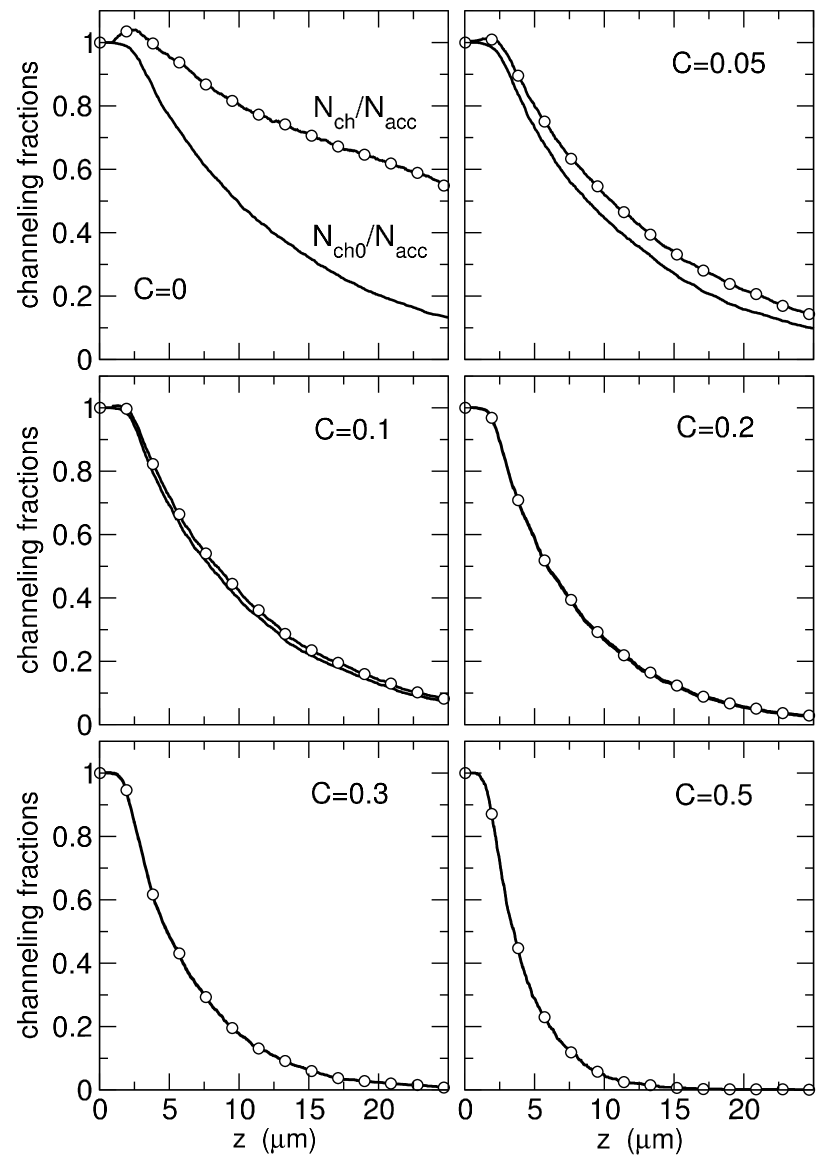
The variation of the amount of channeling particles along the crystal are represented by the two types of fractions, the primary channeling fraction and the channeling fraction . For each , these fractions are determined by the numbers and of the channeling projectiles in the primary channeling segment and anywhere in the crystal, respectively. The first fraction is solely contributed by these accepted projectiles that keep moving in the channeling mode until they experience the first de-channeling. The second fraction is additionally contributed by the projectiles (not necessarily accepted ones) that enter the channeling mode as a result of re-channeling.
The radiation produced by the projectiles is computed according to the quasi-classical formalism Baier . A spectral intensity of the radiation within the cone along the beam direction from is evaluated as
| (3) |
where the sum runs over the simulated trajectories of the total number . The integration over the radiation angles is performed numerically. For the relativistic particles, the radiation is mostly concentrated within the cone , where is the Lorentz-factor corresponding to the beam energy. As in the previous simulations, we compute the radiation spectra for two different aperture values , much smaller and much larger than , respectively.
The above described simulation procedure has been applied to study the channeling and radiation for the electrons with the energy MeV passing through the straight, uniformly bent and periodically bent (110) diamond structures of the thickness m in the beam direction. The numbers of the simulated trajectories varied between and and provided the results with statistical uncertainties with being the standard deviations (i.e., the uncertainties indicated in the tables and plots correspond to a confidence interval). For the periodical bending, we picked up a particular amplitude Å and a period m of large-amplitude long-period diamond CU used in the experiments at MAMI. When referring to a CU in what follows, we will assume, if not explicitly specified otherwise, the diamond (110) sample with the above parameters.
3 Channeling properties
We have first studied the effect of uniform bending on the acceptance and penetration properties of electrons. The values of , , and obtained for the straight and bent crystals are given in Table 1. For each value of the bending radius , we have also calculated the bending parameter as the ratio of two opposite forces: the centrifugal force and the stabilizing force GeV/cm estimated as the maximal gradient of a continuous inter-planar potential in the diamond (110) ChannelingBook2014 .
| (cm) | m) | m) | m) | ||
|---|---|---|---|---|---|
| 0.00 | 0.73 | ||||
| 6.11 | 0.02 | 0.73 | |||
| 2.44 | 0.05 | 0.67 | |||
| 1.74 | 0.07 | 0.62 | |||
| 1.22 | 0.10 | 0.57 | |||
| 0.81 | 0.15 | 0.50 | |||
| 0.61 | 0.20 | 0.45 | |||
| 0.49 | 0.25 | 0.40 | |||
| 0.41 | 0.30 | 0.36 | |||
| 0.39 | 0.35 | 0.32 | |||
| 0.31 | 0.40 | 0.30 | |||
| 0.24 | 0.50 | 0.24 |
The acceptance and lengths are maximal for the straight crystal (, ). With increasing bending radius, they gradually decrease. For the values of bending parameter not exceeding , the channeling lengths exhibit statistically significant excess over the penetration depths, indicating thereby an effectiveness of the re-channeling process. For the bending with larger , the re-channeling events become rare as reflected by close values of and . The total channeling length decreases with stronger rate as compared to decrease of and . The latter behavior reflects deteriorating possibilities for the projectiles to enter the channeling regime of motion. We notice that there are no peculiarities in decreasing the acceptance and the lengths and can conclude that increasing bending suppresses channeling along overall crystal, i.e. just as in the primary channeling segments so also in the following segments that may result from the re-channeling. Such an effect of the bending on the channeling properties is additionally demonstrated by the plots of the channeling fractions (see Figure 1). At any along the beam path in the crystal, both the amounts of the primary channeling electrons (solid lines in the plots) and the amounts including the re-channeled projectiles (dots connected by the lines) are smaller for stronger bending (larger values of ). An excess of the number of the electrons that channel both upon entering the crystal as well as having experienced the re-channeling over the number of the primary channeling electrons is most prominent for the straight crystal (see the plot for ). With increasing , this excess diminishes and for becomes hardly observable indicating the re-channeling to not develop in any noticeable extent.
Next we turn to the channeling properties for the periodically bent diamond. Table 2 presents the values , , and obtained from the simulations for the bending period m and amplitudes varying from zero (the reference case of a straight crystal) to Å. To compare the results with the these for the uniform bending, it is instructive to refer them to the values for the bending parameter. For the periodical profile (2) the curvature
| (4) |
as a function of varies with the period between the zero and maximum values, with being the mean curvature. Notice that Eq. (4) does not account for the slop which is small compared to unity. For more flexibility in relating the periodical bending to the uniform one, we have included in the table both the mean and the maximal values for the bending parameter.
| (Å) | m) | m) | m) | |||
|---|---|---|---|---|---|---|
| 0.0 | 0.00 | 0.00 | 0.73 | |||
| 0.5 | 0.06 | 0.10 | 0.62 | |||
| 1.0 | 0.12 | 0.19 | 0.53 | |||
| 1.5 | 0.19 | 0.29 | 0.44 | |||
| 2.0 | 0.24 | 0.38 | 0.38 | |||
| 2.5 | 0.31 | 0.48 | 0.33 | |||
| 3.0 | 0.37 | 0.58 | 0.28 | |||
| 3.5 | 0.43 | 0.68 | 0.22 | |||
| 4.0 | 0.49 | 0.77 | 0.19 | |||
| 4.5 | 0.55 | 0.87 | 0.15 | |||
| 5.0 | 0.62 | 0.97 | 0.12 | |||
| 5.5 | 0.68 | 1.06 | 0.08 |
The acceptance and the lengths in Table 2, being maximal for the straight crystal, decrease with increasing the bending amplitude and related values and of the bending parameter. Such a behavior is similar to that studied for the bending with constant radius, however for the periodical bending the channeling length remains larger than the penetration depth , even for the largest amplitude m and corresponding values and . Notice that the two latter estimates of the bending parameter substantially exceed the value beyond which the re-channeling appears to be completely suppressed in the uniformly bent crystals. Therefore, in the periodically bent structures, the increasing curvature (reflected by the increasing mean and maximal values for the parameter ) appears to not deteriorate the channeling as strong as in the arc-shape structures. In fact, the periodical bending can even enhance the re-channeling process, as we discuss below.
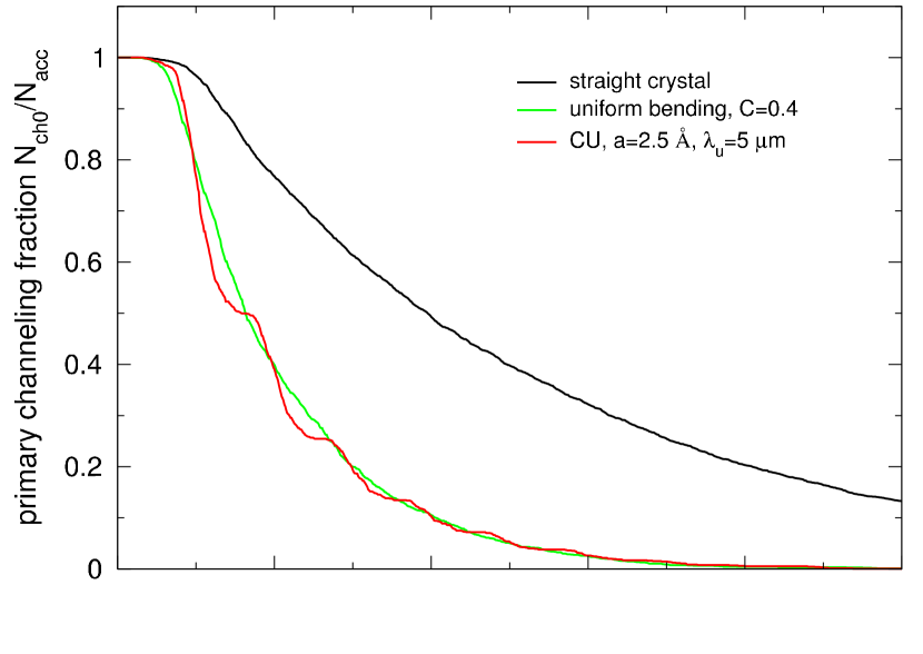
For a particular bending amplitude m we have calculated the fractions of the electrons displaying a channeling motion at the distance from the crystalline entrance. They are presented in Fig. 2 and compared with the fractions in the straight and arc-shape crystals. We have found the primary fraction in the crystal bent with a constant radius and to reflect well a smoothed behavior of the primary fraction in the periodically bent crystal, see the right plot in the figure. The selected constant bending parameter gets into the gap between and for the periodical bending. We can therefore conclude that the periodical bending influences the channeling in the primary channeling segment in a same way as for an arc-shape crystal with a -value in between the mean and maximum values for this parameter for the periodical structure. In other words, the de-channeling from the primary channeling segment develops in the periodically bent crystal in a similar way as in the arc-shape crystal.
 |
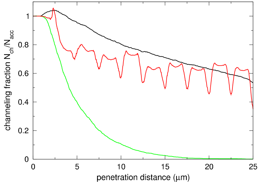 |
As already reflected in Table 1 by the close values of and , the re-channeling in the arc-shape crystal does not develop effectively, and the two channeling fractions (shown by the green curves in Fig. 2) do not exhibit any noticeable difference from each other. In contrast, we encounter a drastically different character for the re-channeling in the undulator. The fraction of the electrons that move in the channeling mode along the periodically bent (110) planes (either upon entering the crystal or having experienced the re-channeling) significantly exceed the fraction of electrons channeling right upon entering the crystal, see the red curves in the figure. Furthermore, the fraction accounting for the re-channeling undergoes remarkable oscillations with varying the penetration distance (see the right plot). It is appealing that after passing a distance of m, the electrons display the channeling fraction with the oscillation maxima even exceeding the fraction of channeling electrons in the straight crystal.
The enhancement of the re-channeling and significant oscillations in the number of channeling electrons in the undulator are the major findings of our studies on the channeling properties. These effects clearly result from the periodical bending. The oscillations of the channeling fraction in the right plot of Fig. 2 exhibit the samples of the double maxima followed by the minima. Along the entire length m of the udulator, we encounter ten such oscillation samples that clearly follow one another with the period m of the varying curvature, Eq. (4). The positions of minima and double maxima correspond to the distances that are even and odd multiplies of , respectively. We can conclude that, at the distances corresponding to the maximal curvature, the effect of de-channeling is maximal leading to the minima of the channeling fraction. In contrast, at the distances where the curvature approaches the zero value, the re-channeling becomes most effective and yields a significant increase in the number of channeling electrons.
It is also remarkable that an average decrease of the channeling fraction with increasing path along the undulator, being rather sharp at m, becomes significantly slower for larger . This can be interpreted as a cumulative effect of re-channeling, since when passing a longer distance the electrons experience more times the zero curvature and encounter situations “optimal” to trigger the non-channeling motion to the channeling one. We remark that according to the diffusion theory of channeling, at sufficiently large distances the decrease of the channeling fraction becomes a power-low one, as it is well displayed in the right plot of the figure by the fractions for the straight crystal and by the average behavior of the fraction in the undulator.
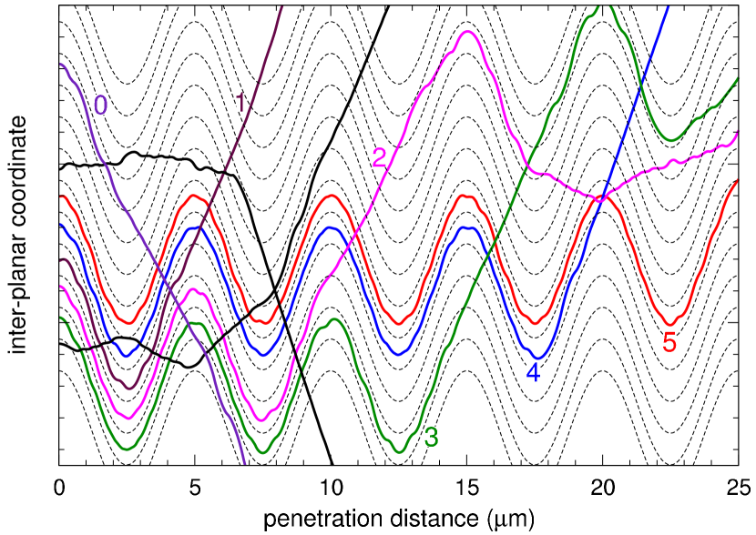
To complete the analysis of channeling in the periodically bent diamond, we present in Fig. 3 a set of simulated electron trajectories. We have included in the figure the trajectories with the channeling motions starting from the crystalline entrance and following a few bending periods, up to the maximal five periods (i.e. passing in the channeling mode through the entire crystal). These trajectories demonstrate that the channeling motion indeed develops in the large-amplitude long period diamond undulator. The figure also shows the trajectories for not-accepted projectiles as well as a trajectory for an accepted particle that stays in the channeling mode along a path shorter than the undulator period. The re-channeling is displayed in the figure by two trajectories that exhibit first the channeling motion (one trajectory - along two and another trajectory - along three undulator periods from the crystalline entrance). Notice that for the latter trajectories the channeling segments following the re-channeling are shorter than (in fact, the lengths of these particular segments slightly exceed ). We will refer to the types of trajectories presented in Fig. 3 when discussing the radiation spectra produced in the undulator.
4 Radiation spectra
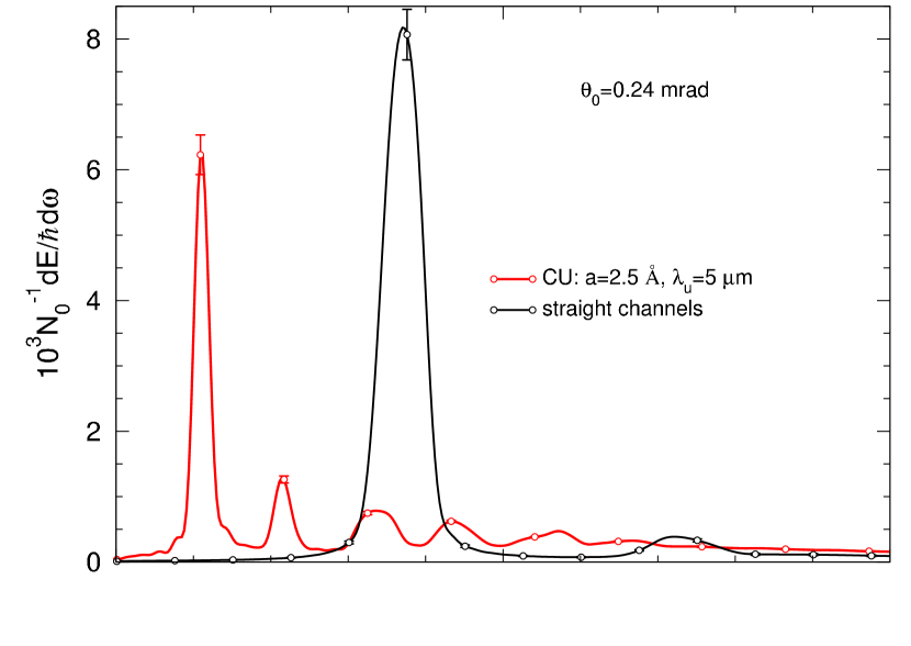
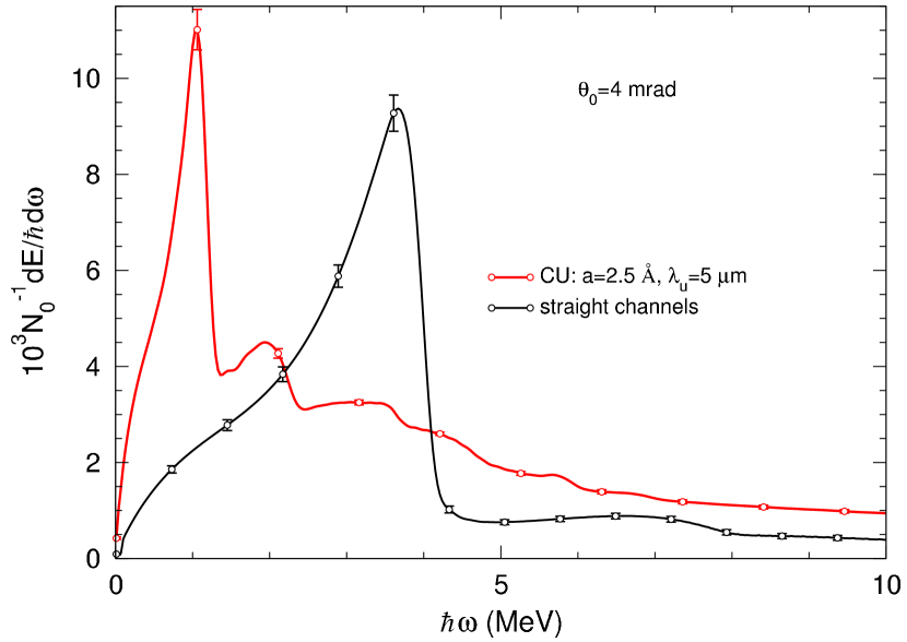
For the MAMI electron beam energy MeV, the natural opening angle for the radiation produced by the projectiles is mrad. The aperture half-width for a detector used in the experiments is mrad Backe_EtAl_PRL2014 ; Backe_private ; Backe_EtAl_2011 ; Backe_EtAl_PRL_115_025504_2015 . We have applied Eq. (3) to calculate the emission spectra for mrad which is close to , and for mrad which significantly exceeds the natural opening angle. The results are presented in Figs. 4 and 5. Fig. 6 shows the spectra that can be produced by the positrons under the same conditions as for the electrons.
 |
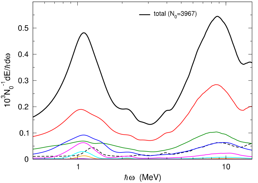 |
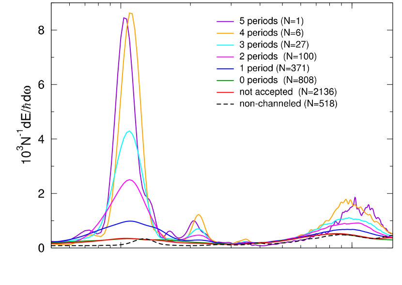
To elucidate the formation of the undulator line in CU, we have computed spectra produced by the electrons moving along specific trajectories. We have selected, from the total amount of simulated trajectories, different groups of trajectories of a same kind. It is natural to expect that the more periods an electron moves in the channeling mode upon entering the crystal, the more intensive udulator line it produces in the radiation spectra. Therefore, we have calculated the spectra for trajectories with the channeling motion along a path which starts from the crystalline entrance and contains a given number of the undulator periods. The number of periods varies from zero (a de-channeling develops before the electron passes the first period) up to the maximum number of five periods (a primary channeling segment of the trajectory covers the entire CU length). For comparison, we have also calculated separate spectra produced by the non-accepted electrons and by the electrons that did not develop a channeling motion in the CU. We refer to Fig. 3 for the examples of trajectories from the different groups. The averaged radiation spectra for each group of the trajectories have a meaning of the spectra which would have been produced if all the simulated trajectories were of the kinds as these in the groups. They are shown in the top plot of Fig. 4. The bottom plot shows the absolute contributions of the spectra formed by the different groups of trajectories into the total simulated radiation spectrum.
The spectra in Fig. 4 clearly display the lines resulting from oscillations in the projectile’s motion. The line positions, being slightly different for different partial spectra, can be deduced from the total simulated spectrum as MeV and MeV for the undulator and channeling lines, respectively. The line intensities and widths also vary from one partial spectrum to another, however the more bending periods the electrons follow in the channeling mode upon entering the CU, the larger is an excess of the undulator line intensities over the channeling ones. The most intensive and narrow undulator lines are produced in the spectra normalized “per a single trajectory” which correspond to four and five full periods of the channeling motion (see the top plot in Fig. 4). These spectra, as well as the spectra for three and two full periods of the channeling motion, also display the lines of the second harmonics of the undulator radiation. The channeling lines are significantly broader than the undulator lines (notice the logarithmic scale for the radiation energies), implying that the channeling oscillations develop in the motion in a less harmonic manner than the undulator oscillations.
 |
 |
Though the undulator lines formed by the trajectories with two to five full CU periods of the channeling motion are intensive in the partial spectra normalized per a single electron (top plot), they have low to moderate weights in the total simulated spectrum (bottom plot) as a result of small statistical wights of the corresponding channeling scenarios. The largest contribution to the total spectrum comes from the non-accepted trajectories. It is however remarkable, that the partial spectra produced by the non-accepted electrons display a prominent undulator line (see the red curves in the plots). The line clearly results from the re-channeling of the electrons and dominantly contributes the undulator line in total spectrum. Thus, the re-channeling, being enhanced by the periodical bending, plays an important role in producing a spectral undulator peak in the radiation from CU.
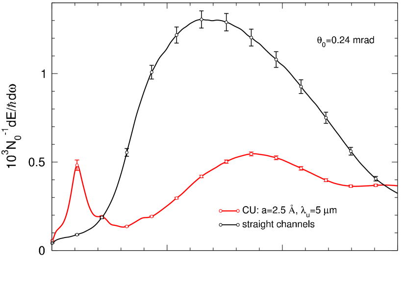
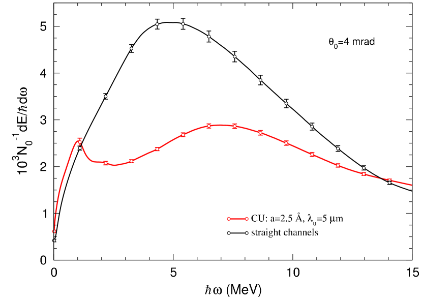
The effect of the radiation aperture on the spectral shape is studied in Fig. 5 where the spectra produced from CU are also compared with the spectra for the straight crystal. For both aperture values selected, mrad (top plot) and mrad (bottom plot), the maxima of the undulator and channeling spectral peaks are well separated from each other and display close intensities. Thus, the lines can be well resolved in an experiment. The peak intensities gain a factor of five with changing the aperture value from the smaller to the larger one. The channeling peak is suppressed in the radiation from CU as compared to the radiation from the straight crystal.
 |
 |
Though the subject of our studies, in relation with the experiments at MAMI, is the channeling of electrons, it is instructive to consider also the channeling of positrons under the same conditions, in particular in the same CU. In Fig. 6, we present the spectra computed from the corresponding simulations for the periodically bent and (for the reference) straight diamond samples. As the channeling motion of the positrons is more harmonic than that of the electrons, the spectra produced by the positrons display more intensive and narrow lines than the spectra for the electrons. In addition to the fundamental undulator peak in the radiation spectra, we encounter a sequence of the higher spectral harmonics. In the simulated spectra one can also distinguish the second spectral harmonics produced due to the channeling oscillations of the positrons, in addition to the well displayed fundamental channeling lines. For the smaller aperture value (top plot in the figure), the spectral lines have symmetric profiles typical for the radiation in the forward () direction. For the larger aperture (bottom plot), the lines become broader towards softer radiation energies, as a result of dependence of the line positions on the radiation angle.
5 Conclusion
We have presented the results of theoretical simulations on the channeling and radiation of the MeV electrons in the straight, arc-bent and periodically bent diamond (110) structures. A particular focus of the studies is on a large-amplitude long-period diamond CU used for the current experiments at MAMI. We have found that an enhanced re-channeling process develops in CU making the channeling very contrast to that in the arc-bent crystals. This process significantly contributes to the formation of the distinct spectral undulator lines in the radiation from CU. The spectral simulations for the positron beam of the same energy reveal the undulator lines even more pronounced as for the electron beam. We expect the results of our studies to be important for the current and future experiments with large-amplitude long-period CUs.
Acknowledgements.
Financial support by the European Commission through the PEARL Project within the H2020-MSCA-RISE-2015 call, GA 690991, is gratefully acknowledged.References
- (1) J. Lindhard, K. Dan. Vidensk. Selsk. Mat. Fys. Medd. 34, 1 (1965).
- (2) A.V. Korol, A.V. Solov’yov, W. Greiner, Channeling and Radiation in Periodically Bent Crystals (Springer-Verlag, Berlin Heidelberg 2014).
- (3) R.G. Polozkov, V.K. Ivanov, G.B. Sushko, A.V. Korol, A.V. Solov’yov, Eur. Phys. J. D 68, 268 (2014).
- (4) A.V. Korol, A.V. Solov’yov, W. Greiner, J. Phys. G 24, L45 (1998).
- (5) A.V. Korol, A.V. Solov’yov, W. Greiner, Int. J. Mod. Phys. E 8, 49 (1999).
- (6) D. Boshoff, M. Copeland, F. Haffejee, Q. Kilbourn, C. Mercer, A. Osatov, C. Williamson, P. Sihoyiya, M. Motsoai, C.A. Henning, S.H. Connell, T. Brooks, J. Härtwig, T.-N. Tran Thi, N. Palmer, U. Uggerhøj, 4th Int. Conf. “Dynamics of Systems on the Nanoscale” (Bad Ems, Germany, Oct. 3-7 2016) Book of Abstracts, p. 38.
- (7) H. Backe, W. Lauth, 4th Int. Conf. “Dynamics of Systems on the Nanoscale” (Bad Ems, Germany, Oct. 3-7 2016) Book of Abstracts, p. 58.
- (8) W. Lauth, H. Backe, R. Barret, T.N. Tran Caliste, J. Härtwig, D. Eon, 4th Int. Conf. “Dynamics of Systems on the Nanoscale” (Bad Ems, Germany, Oct. 3-7 2016), Book of Abstracts, p. 63.
- (9) U. Wienands, Talk at the 7th Int. Conf. “Channeling 2016 - Charged&Neutral Particles Channeling Phenomena” (Sirmione del Garda, Italy, Sept. 25-30 2016).
- (10) A. Kostyuk, Phys. Rev. Lett. 110, 115503 (2013).
- (11) G.B. Sushko, V.G. Bezchastnov, A.V. Korol, W. Greiner, A.V. Solov’yov, R.G. Polozkov, V.K. Ivanov, J. Phys.: Conf. Ser. 438, 012019 (2013).
- (12) G.B. Sushko, A.V. Korol, W. Greiner, A.V. Solov’yov, J. Phys.: Conf. Ser. 438, 012018 (2013).
- (13) T.N. Wistisen, K.K. Andersen, S. Yilmaz, R. Mikkelsen, J.L. Hansen, U.I. Uggerhøj, W. Lauth, H. Backe, Phys. Rev. Lett. 112, 254801 (2014).
- (14) V.G. Bezchastnov, A.V. Korol, A.V. Solov’yov, J. Phys. B 47, 195401 (2014).
- (15) G.B. Sushko, A.V. Korol, A.V Solov’yov, Nucl. Instrum. Meth. B 355, 39 (2015).
- (16) T.N. Wistisen, U.I. Uggerhøj, U. Wielands, T.W. Markiewicz, R.J. Noble, B.C. Benson, T. Smith, E. Bagli, L. Bandiera, G. Germogli, V. Guidi, A. Mazzolari, R. Holtzapple, and S. Tucker, Phys. Rev. Acc. B. 19, 071001 (2016).
- (17) A.V. Korol, V.G. Bezchastnov, G.B. Sushko, A.V Solov’yov, Nucl. Instrum. Meth. B 387, 41 (2016).
- (18) H. Backe, private communication (2016).
- (19) G.B. Sushko, V.G. Bezchastnov, I.A. Solov’yov, A.V. Korol, W. Greiner, A.V. Solov’yov, J. Comp. Phys. 252, 404 (2013).
- (20) I.A. Solov’yov, A.V. Yakubovich, P.V. Nikolaev, I. Volkovets, A.V. Solov’yov, J. Comp. Chem. 33, 2412 (2012).
- (21) http://www.mbnexplorer.com/
- (22) V.N. Baier, V.M. Katkov, V.M. Strakhovenko, Electromagnetic Processes at High Energies in Oriented Single Crystals (World Scientific, Singapore 1988).
- (23) H. Backe, D. Krambrich, W. Lauth, J.L. Hansen, U.K.I. Uggerhøj, Nuovo Cimento C 34, 157 (2001).
- (24) L. Bandiera, E. Bagli, G. Germogli, V. Guidi, A. Mazzolari, H. Backe, W. Lauth, A. Berra, D. Lietti, M. Prest, D. De Salvador, E. Vallazza, V. Tikhomirov, Phys. Rev. Lett. 115, 025504 (2015).