Buckling-Induced Kirigami
Abstract
We investigate the mechanical response of thin sheets perforated with a square array of mutually orthogonal cuts, which leaves a network of squares connected by small ligaments. Our combined analytical, experimental and numerical results indicate that under uniaxial tension the ligaments buckle out-of-plane, inducing the formation of 3D patterns whose morphology is controlled by the load direction. We also find that by largely stretching the buckled perforated sheets, plastic strains develop in the ligaments. This gives rise to the formation of kirigami sheets comprising periodic distribution of cuts and permanent folds. As such, the proposed buckling-induced pop-up strategy points to a simple route for manufacturing complex morphable structures out of flat perforated sheets.
In recent years, origami Mahadevan2005 ; Wei2013 ; Schenk2013 ; Tachi2013 ; Silverberg2014 ; Yasuda2015 ; Silverberg2015 ; Overvelde2016 ; Dudte2016 and kirigami Castle2014 ; Isobe2016 ; Sussman2015 ; Eidini2015 ; Chen2016 ; Tang2016 ; Seffen2016 ; Shyu2015 ; Blees2015 ; Song2015 ; Lamoureux2015 ; Wu2016 ; Zhang2015 ; Eidini2016 ; Castle2016 ; Neville2016 ; Yan2016 ; Norman1993 have become emergent tools to design programmable and reconfigurable mechanical metamaterials. Origami-inspired metamaterials are created by folding thin sheets along predefined creases, whereas kirigami allows the practitioner to exploit cuts in addition to folds to achieve large deformations and create 3D objects from a flat sheet. Therefore, kirigami principles have been exploited to design highly stretchable devices Norman1993 ; Song2015 ; Shyu2015 ; Blees2015 ; Lamoureux2015 ; Wu2016 ; Isobe2016 and morphable structures Zhang2015 ; Yan2016 ; Neville2016 . Interestingly, several of these studies also show that pre-creased folds are not necessary to form complex 3D patterns, as mechanical instabilities in flat sheets with an embedded array of cuts can result in out-of-plane deformation Norman1993 ; Shyu2015 ; Blees2015 ; Lamoureux2015 ; Isobe2016 ; Zhang2015 ; Wu2016 ; Yan2016 . However, while a wide range of 3D architectures have been realized by triggering buckling under compressive stresses Zhang2015 ; Yan2016 , instability-induced kirigami designs subjected to tensile loading are limited to a single incision pattern comprised of parallel cuts in a centered rectangular arrangement Shyu2015 ; Blees2015 ; Lamoureux2015 ; Norman1993 ; Isobe2016 .
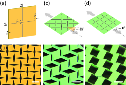
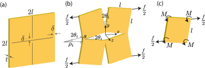
In this Letter, we investigate the tensile response of elastic sheets of thickness perforated with a square array of mutually orthogonal cuts. This perforation pattern introduces a network of square domains of edge separated by hinges of width [Fig. 1(a)]. While the planar response of such perforated sheets in the thick limit (i.e. for large values of ) has received significant attention, as it is characterized by effective negative Poisson’s ratio Grima2000 ; Grima2005 ; Grima2011 ; Cho2014 ; Gatt2015 ; Shan2015 ; Suzuki2016 ; Vasiliev2002 ; Rafsanjani2016 [Fig. 1(b)], here we add another dimension and study how the behavior of the system evolves when the thickness is progressively decreased (i.e. for decreasing values of ). Our combined analytical, numerical and experimental results indicate that in sufficiently thin sheets mechanical instabilities triggered under uniaxial tension can be exploited to create complex 3D patterns and even to guide the formation of permanent folds. We also find that the morphology of the instability-induced patterns is strongly affected by the loading direction (see Figs. 1(c)-(d) and Movies 1 in Supplemental Material SI ), pointing to an effective strategy to realize functional surfaces characterized by a variety of architectures.
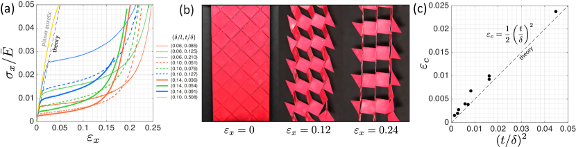
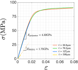
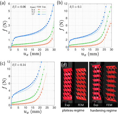
We start by experimentally investigating the effect of the sheet thickness and hinge width on the response of the system subjected to uniaxial tension along the square diagonals [i.e. for - Fig. 1(c)]. Specimens are fabricated by laser cutting an array of mutually perpendicular cuts [see Fig. 2(b)] into plastic sheets (Artus Corporation, NJ) with Young’s modulus and Poisson’s ratio (see Supplemental Material: Experiments SI ). In Fig. 2(a), we report the experimental stress-strain responses for 10 samples characterized by different values of normalized thickness and normalized hinge width .
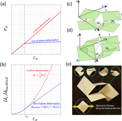
First, it is apparent that the initial response for all samples is linear. At this stage, all hinges bend in-plane, inducing pronounced rotations of the square domains [Fig. 1(b)], which result in large negative values of the macroscopic Poisson’s ratio Vasiliev2002 ; Grima2005 . As such, the stiffness of the perforated sheets, , is governed by the in-plane flexural deformation of the hinges and it can be shown that (see Supplemental Material: Analytical Exploration SI ):
| (1) |
Second, for the thin samples (i.e. ), the curves reported in Fig. 2(a) also show a sudden departure from linearity to a plateau stress caused by the out-of-plane buckling of the hinges. Such buckling in turn induces out-of plane rotations of both the square domains and the cuts, which arrange to form a 3D pattern reminiscent of a misaligned Miura-ori Saito2016 with an alternation of square solid faces (corresponding to the square domains) and rhombic open ones (defined by the cuts) (see Fig. 1(c), Fig. 2(b) at and Movie 2 in Supplemental Material SI ). To characterize the critical strain, , at which the instability is triggered, we start by noting that since the stress immediately after instability is almost constant, the contribution of out-of-plane strain energy should be linear in , (see Supplemental Material: Analytical exploration SI )
| (2) |
Moreover, assuming that the square domains remain rigid and that the deformation localizes at the hinges which can be modeled as flexural beam segments, can also be written as
| (3) |
where , and is the opening angle of each cut after out-of-plane buckling, which for is approximated by
| (4) |
Finally, by equating Eqs. (2) and (3) we find that
| (5) |
which despite the simplifications made, compares very well with our experimental results [Fig. 2(c)] and numerical simulations [Fig. S6]. Note that a similar expression for the critical strain has been previously obtained for kirigami patterns comprising parallel cuts in a centered rectangular arrangement Isobe2016 .
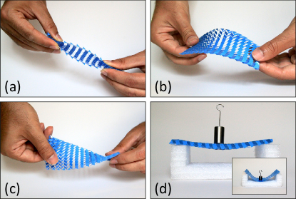
Third, for large enough values of the applied strain , the stress rises sharply again. This regime starts when the square domains align [Fig. 2(b) at ] and the deformation mechanism of the hinges switches from bending- to stretching-dominated. At this stage, localized zone of intense strain (of plastic nature) develop in the hinges and result in the formation of permanent folds. Although we start with a flat elastic sheet with an embedded array of cuts (i.e. a perforated sheet), by largely stretching it we form a system that comprises a periodic distribution of both cuts and folds (i.e. a kirigami sheet). In particular, we note that our kirigami sheets possess several deformation characteristics of the Miura-ori Schenk2013 ; Wei2013 and zigzag-base folded kirigami Eidini2015 ; Eidini2016 (see Movie 3 in Supplemental Material SI ), as () they are flat-foldable [Fig. 3(a)]; () they form a saddle shape with a negative Gaussian curvature upon non-planar bending [Fig. 3(b)]; and () they can be twisted under anti-symmetric out-of-plane deformation, [Fig. 3(c)]. However, in contrast to the Miura-ori, misaligned Miura-ori and zigzag-base folded kirigami, the macroscopic Poisson’s ratio of our kirigami sheets is positive (see Movie 4 in Supplemental Material SI ). This is the result of the fact that not all the faces are rigid. As such, the applied tensile deformation not only results in the rotation of the faces about the connecting ridges, but also in the deformation of those defined by the cuts, allowing lateral contraction of the structure. It is also noteworthy that, differently from the misaligned Miura-ori that can only be folded to a plane, the additional degree of freedom provided by the open cuts allow the Miura kirigami to be laterally flat-foldable [Movie 4]. Finally, we note that our Miura kirigami structures have higher bending rigidity than the corresponding flat perforated sheet (see Fig. 3(d) and Movie 3 in Supplemental Material SI ).
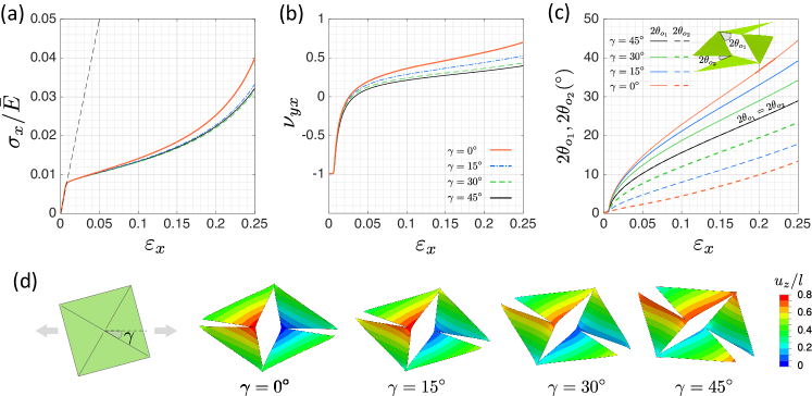
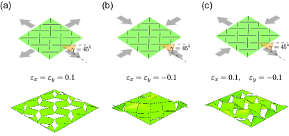
Having determined that instabilities in thin sheets with an embedded array of mutually perpendicular cuts can be harnessed to form complex 3D patterns, we further explore the design space using Finite Element (FE) analyses (See Supplemental Material: FE Simulations SI ). We start by numerically investigating the response of finite size samples stretched along the square diagonals (i.e. ) and find excellent agreement with the experimental results (Fig. S5 and Movie 2 in Supplemental Material SI ). This validates the numerical analyses and indicates that they can be effectively used to explore the response of the system. First, we use the simulations to understand how plastic deformation evolves. By monitoring the distribution of the von Mises stress within the sheets, we find that that plastic deformation initiates at the tip of hinges well after the buckling onset [see Figs. S6 and S9] and then gradually expand to fully cover the hinges when the sample is fully stretched and the deformation mechanism changes from bending-dominated to stretching-dominated. Second, we numerically explore the effect of different loading conditions and find that uniaxial tension is the ideal one to trigger the formation of well-organized out-of-plane patterns in our perforated sheets [see Fig. S7]. Third, we investigate the effect of the loading direction by simulating the response of periodic unit cells. In Fig. 4(a) we report the stress-strain responses obtained numerically for perforated sheets characterized by and loaded uniaxially for , and . Our results indicate that the mechanical response of the perforated sheets under uniaxial tension is minimally affected by the loading direction. In fact, the evolution of both stress [Fig. 4(a)] and macroscopic in-plane Poisson’s ratio [Fig. 4(b)] are similar for different values of . By contrast, we find that the morphology of the 3D patterns induced by the instability is significantly affected by [Fig. 4(c)-(d)]. As the loading directions varies from to , the symmetry in opening angle of the two sets of perpendicular cuts breaks. While for all cuts open equally (i.e. ), as we reduce , one set becomes wider (i.e. monotonically increases) and the other progressively narrower (i.e. monotonically decreases)[Fig. 4(c)]. In the limit case of one set of cuts remains almost closed and a 3D cubic pattern emerge after buckling [Fig. 1(d), Movie 5]. Furthermore, permanent folds with direction controlled by can be introduced by largely stretching the perforated sheets. As such, by controlling the loading direction a variety of kirigami sheets can be formed [Movie 6]. While all of them are laterally flat-foldable, we find that by increasing from to the resulting kirigami sheets have higher bending rigidity and their Gaussian curvature varies from zero (for ) to large negative values (for ). Furthermore, by increasing , the resulting kirigami sheets become more compliant under torsion (Movie 6 in Supplemental Material SI ).
In summary, our combined experimental, analytical and numerical study indicates that buckling in thin sheets perforated with a square array of cuts and subjected to uniaxial tension can be exploited to form 3D patterns and even create periodic arrangements of permanent folds. While buckling phenomena in cracked thin plates subjected to tension have traditionally been regarded as a route toward failure Zielsdorff1972 , we show that they can also be exploited to transform flat perforated sheets to kirigami surfaces. Our buckling-induced strategy not only provides a simple route for manufacturing kirigami sheets, but can also be combined with optimization techniques to design perforated patterns capable of generating desired complex 3D surfaces under external loading Sussman2015 ; Dudte2016 ; Konakovic2016 . Finally, since the response of our perforated sheets is essentially scale-free, the proposed pop-up strategy can be used to fabricate kirigami sheets over a wide range of scales, from transformable meter-scale architectures to tunable nano-scale surfaces Cavallo2014 ; Wu2016 .
Acknowledgements
K.B. acknowledges support from the National Science Foundation under grant number DMR-1420570 and CMMI-1149456. A.R. also acknowledges the financial support provided by Swiss National Science Foundation (SNSF) under grant number 164648. The authors thank Bolei Deng for fruitful discussions, Yuerou Zhang for assistance in laser cutting and Matheus Fernandes for proofreading the manuscript.
References
- (1) L. Mahadevan and S. Rica, Self-organized origami, Science 307, 1740 (2005).
- (2) M. Schenk, and S. D. Guest, Geometry of Miura-folded metamaterials. Proc. Natl. Acad. Sci. USA 110, 3276 (2013).
- (3) Z. Y. Wei, Z. V. Guo, L. Dudte, H. Y. Liang, and L. Mahadevan, Geometric Mechanics of Periodic Pleated Origami, Phys. Rev. Lett. 110, 215501 (2013).
- (4) T. Tachi, Designing freeform origami tessellations by generalizing Resch’s patterns, ASME J. Mech. Design 135, 111006 (2013).
- (5) J. L. Silverberg, A. A. Evans, L. McLeod, R. C. Hayward, T. Hull, C. D. Santangelo, and I. Cohen, Using origami design principles to fold reprogrammable mechanical metamaterials, Science 345, 647 (2014).
- (6) H. Yasuda, and J. Yang, Reentrant origami-based metamaterials with negative Poisson’s ratio and bistability. Phys. Rev. Lett. 114, 185502 (2015).
- (7) J. L. Silverberg, J-H. Na, A. A. Evans, B. Liu, T. C. Hull, C. D. Santangelo, R. J. Lang, R. C. Hayward, and I. Cohen, Origami structures with a critical transition to bistability arising from hidden degrees of freedom, Nat. Mat. 14, 389 (2015).
- (8) J. T. B. Overvelde, T. A. de Jong, Y. Shevchenko, S. A. Becerra, G. M. Whitesides, J. C. Weaver, C. Hoberman, K. Bertoldi, A three-dimensional actuated origami-inspired transformable metamaterial with multiple degrees of freedom, Nat. Comm. 7, 10929 (2016).
- (9) L. H. Dudte, E. Vouga, T. Tachi, and L. Mahadevan, Programming curvature using origami tessellations, Nat. Mat. 15, 583 (2016).
- (10) T. Castle, Y. Cho, X. Gong, E. Jung, D. M. Sussman, S. Yang, and R. D. Kamien, Making the Cut: Lattice Kirigami Rules. Phys. Rev. Lett. 113, 245502 (2014).
- (11) D. M. Sussman, Y. Cho, T. Castle, X. Gong, E. Jung, S. Yang, and R. D. Kamien, Algorithmic lattice kirigami: A route to pluripotent materials, Proc. Natl. Acad. Sci. USA 112, 7449 (2015).
- (12) M. Eidini and G. H. Paulino, Unraveling metamaterial properties in zigzag-base folded sheets, Sci. Adv. 1, e1500224 (2015).
- (13) M. Eidini, Zigzag-base folded sheet cellular mechanical metamaterials, Ext. Mech. Lett. 6 96 (2016).
- (14) T. Castle, D. M. Sussman, M. Tanis and R. D. Kamien, Additive lattice kirigami Sci. Adv. 2, e1601258 (2016).
- (15) B. G. Chen, B. Liu, A. A. Evans, J. Paulose, I. Cohen, V. Vitelli, and C. D. Santangelo. Topological Mechanics of Origami and Kirigami. Phys. Rev. Lett. 116, 135501 (2016).
- (16) Y. Tang and J. Yin, Design of cut unit geometry in hierarchical kirigami-based auxetic metamaterials for high stretchability and compressibility, Ext. Mech. Lett. in press (2016).
- (17) K. A. Seffen, k-cones and kirigami metamaterials Phys. Rev. E 94, 033003 (2016).
- (18) Z. Song, X. Wang, C. Lv, Y. An, M. Liang, T. Ma, D. He, Y-J. Zheng, S-Q. Huang, H. Yu, and H. Jiang, Kirigami-based stretchable lithium-ion batteries Sci. Rep. 5, 10988 (2015).
- (19) T. C. Shyu, P. F. Damasceno, P. M. Dodd, A. Lamoureux, L. Xu, M. Shlian, M. Shtein, S. C. Glotzer, and N. A. Kotov, A kirigami approach to engineering elasticity in nanocomposites through patterned defects, Nat. Mat. 14, 785 (2015).
- (20) M. K. Blees, A. W. Barnard, P. A. Rose, S. P. Roberts, K. L. McGill, P. Y. Huang, A. R. Ruyack, J. W. Kevek, B. Kobrin, D. A. Muller, and P. L. McEuen, Graphene kirigami, Nature 524 204 (2015).
- (21) A. Lamoureux, K. Lee, M. Shlian, S. R. Forrest, and M. Shtein, Dynamic kirigami structures for integrated solar tracking, Nat. Comm. 6, 8092 (2015).
- (22) D. Norman, The mounting of single leaf parchment and vellum objects for display and storage, V&A Conserv. J., 9, 10 (1999).
- (23) M. Isobe and K. Okumura, Initial rigid response and softening transition of highly stretchable kirigami sheet materials, Sci. Rep. 6, 24758 (2016).
- (24) C. Wu, X. Wang, L. Lin, H. Guo,and Z. L. Wang, Paper-based triboelectric nanogenerators made of stretchable interlocking kirigami patterns ACS Nano 10, 4652 (2016).
- (25) Y. Zhang, Z. Yan, K. Nan, D. Xiao, Y. Liu, H. Luan, H. Fu, X. Wang, Q. Yang, J. Wang, W. Ren, H. Si, F. Liu, L. Yang, H. Li, J. Wang, X. Guo, H. Luo, L. Wang, Y. Huang, J. A. Rogers, A mechanically driven form of Kirigami as a route to 3D mesostructures in micro/nanomembranes, Proc. Natl. Acad. Sci. USA 112, 11757 (2015).
- (26) Z. Yan, F. Zhang, J. Wang, F. Liu, X. Guo, K. Nan, Q. Lin, M. Gao, D. Xiao, Y. Shi, Y. Qiu, H. Luan, J. H. Kim, Y. Wang, H. Luo, M. Han, Y. Huang, Y. Zhang, J. A. Rogers, Controlled Mechanical Buckling for Origami-Inspired Construction of 3D Microstructures in Advanced Materials Adv. Func. Mater. 26, 2629 (2016).
- (27) R. M. Neville, F. Scarpa, and Alberto Pirrera, Shape morphing Kirigami mechanical metamaterials Sci. Rep. 6, 31067 (2016).
- (28) J. N. Grima and K. E. Evans, Auxetic behavior from rotating squares, J. Mat. Sci. Lett. 19, 1563 (2000).
- (29) A. A. Vasiliev, S. V. Dmitriev, Y. Ishibashi and T. Shigenari Elastic properties of a two-dimensional model of crystals containing particles with rotational degrees of freedom. Phys. Rev. B 65, 094101 (2002).
- (30) J. N. Grima, A. Alderson and K. E. Evans, Auxetic behaviour from rotating rigid units phys. stat. sol. (b) 242, 561 (2005).
- (31) S. Shan S., S. H. Kang, Z. Zhao, L. Fang, and K. Bertoldi, Design of planar isotropic negative Poisson’s ratio structures, Ext. Mech. Lett. 4, 96 (2015).
- (32) Y. Cho, J-H Shin, A. Costa, T. A. Kim, V. Kunin, J. Li, S. Yeon Lee, S. Yang, H. N. Han, I-S Choi, and D. J. Srolovitz, Engineering the shape and structure of materials by fractal cut, Proc. Natl. Acad. Sci. USA 111, 17390 (2014).
- (33) R. Gatt, L. Mizzi, J. I. Azzopardi, K. M. Azzopardi, D. Attard, A. Casha, J. Briffa, J. N. Grima, Hierarchical auxetic mechanical metamaterials, Sci. Rep. 5, 8395 (2015).
- (34) Y. Suzuki, G. Cardone, D. Restrepo, P. D. Zavattieri, T. S. Baker, A. F. Tezcan, Self-assembly of coherently dynamic, auxetic, two-dimensional protein crystals, Nature 533, 369 (2016).
- (35) J. N. Grima, E. Manicaro, and D. Attard, Auxetic behaviour from connected different-sized squares and rectangles, Proc. R. Soc. A 467, 439 (2011)
- (36) A. Rafsanjani and D. Pasini, Bistable Auxetic Mechanical Metamaterials Inspired by Ancient Geometric Motifs, Ext. Mech. Lett. 9, 291 (2016).
- (37) See Supplemental Material at URL which includes Refs. Grima2000 ; Grima2005 ; Vasiliev2002 , supporting movies, an analytical exploration, details of the FE simulations and a description of the experiments.
- (38) K. Saito, A. Tsukahara, and Y. Okabe, Designing of self-deploying origami structures using geometrically misaligned crease patterns, Proc. R. Soc. A 472, 20150235 (2016)
- (39) G.F. Zielsdorff and R. L. Carlson, On the buckling of thin tensioned sheets with cracks and slots, Eng. Frac. Mech. 4, 939 (1972).
- (40) F. Cavallo, Y. Huang, E. W. Dent, J. C. Williams, and M. G. Lagally, Neurite Guidance and Three-Dimensional Confinement via Compliant Semiconductor Scaffolds, ACS Nano 8, 12219 (2014).
- (41) M. Konaković, K. Crane, B. Deng, S. Bouaziz, D. Piker, and M. Pauly, Beyond developable: computational design and fabrication with auxetic materials ACM. Trans. Graph. 35(4) no. 89 (2016)
I SUPPLEMENTAL MATERIALS
I.1 Analytical Exploration
To get a deeper understanding of the mechanical response of the considered patterned sheets, we analytically investigate their behavior. We first study the initial in-plane linear elastic response of the system and then characterize the onset of instability resulting in the formation of 3D patterns. In all our calculations we assume that all deformation is localized at the hinges and that the square domains are rigid.
Initial in-plane linear elastic response. The stress-strain curves shown in Fig. 2a of the main text show that the response of all samples is initially linear. Here, we derive an analytical relation for the effective Young’s modulus of the perforated sheets, , in terms of the geometrical parameters and , and the Young’s modulus of the sheet .
We focus on a unit cell comprising four square domains [Fig. S1(a)] and deform it uniaxially along one set of cuts (i.e. ) by applying a macroscopic stress , where is the force applied to the hinges on the vertical boundaries and denotes its cross sectional area [Fig. S1(b)]. It is important to note that using standard axis transformation techniques it has been shown that the planar response of such perforated sheets is not affected by the loading direction Vasiliev2002 ; Grima2005 . Therefore, although here for the sake of simplicity we consider , we expect to be identical for any loading direction (i.e. for any value of ).
The applied uniaxial stress generates identical bending moments at all hinges, which in turn induce the rotation of all square domains by an angle and the opening of the all cuts by an angle [Fig. S1(b)]. Focusing on a single square domain [Fig. S1(c)], it is easy to see that:
| (S1) |
Moreover, since must be balanced by the couple induced by the internal loads, we have:
| (S2) |
where is the second moment of area of each hinge about the -axis and denotes the curvature of each bent hinge. Assuming that the length of the bent region of the hinge is approximately equal to the hinge width , we obtain:
| (S3) |
Moreover, since the strain in the loading direction is given by:
| (S5) |
in the small deformation regime (i.e. ) we have:
| (S6) |
so that
| (S7) |
It follows that the effective Young’s modulus of perforated sheet, , is:
| (S8) |
Finally, we note that considering each hinge as a beam of thickness and width , its strain energy density under in-plane deformation can be calculated as:
| (S9) |
where is the volume of the unit cell. The in-plane strain energy density of a unit cell comprising eight hinges is then given by:
| (S10) |
Transition from in-plane to out-of-plane response. The stress-strain curves reported in Fig. 1a of the main text also show that the thin samples (i.e. ) are characterized by a sudden departure from linearity to a plateau stress. This sudden departure from linearity is the result of out-of-plane buckling of the ligaments and occurs when the out-of-plane deformation of the hinges becomes energetically less costly than their in-plane deformation. While the strain energy density of a perforated sheet that has deformed in-plane is given by Eq. (S10), the strain energy density of a perforated sheet that has deformed out-of plane can be expressed as:
| (S11) |
where is the critical strain at which buckling occurs and is energy contribution due to the out-of-plane deformation.
Since and the stress immediately after instability is almost constant [Fig. S2(b)], it follows that is approximately linear in [Fig. S2(a)] and can be identified as the tangent of at :
| (S12) |
Moreover, as all hinges bend out-of-plane, can also be expressed as:
| (S13) |
where is the second moment of area with respect to -axis (-axis) for hinges along -axis (-axis), is the out-of-plane curvature of the deformed hinges and is the opening angle of an hinge after out-of-plane buckling. Note that, in general, after buckling the opening angles of the hinges within the perforate sheet can take two values, and (i.e. not all hinges open equally after buckling).
While Eq. (S13) is valid for any loading direction, for (i.e. loading along the square diagonals) , so that Eq. (S13) simplifies to:
| (S14) |
The critical strain can then be determined by equation Eqs. (S12) and (S14) after having expressed as a function of . To this end, we first note that for [Fig. S2(d)]
| (S15) |
where determines the orientation of the square domains with respect to -plane and
| (S16) |
is the angle between the edge of the square domain placed on the -plane and the -axis.
Moreover, since the experiments indicate that for the hinges are approximately aligned along the loading direction [see paper illustration in Fig. S2(e)], the distance between points A and B shown in Fig. S2(d) remains constant (i.e. ) and
| (S17) |
While Eq. (S17) is exact well into the postbuckling regime, it does not correctly capture the response of the system at the onset of instability, as it predicts for (i.e. it predicts that the square are already rotated out of the -plane when the instability is triggered). To correct for this, we modify Eq. (S17) as
| (S18) |
where denotes the opening angle associated to . Note that, according to Eq. (S18), at Substitution of Eqs. (S16) and (S18) into Eq. (S15) yields:
| (S19) |
Although Eq. (S19) provides a highly non-linear relation between and , close to the instability point can be approximated as
| (S20) |
and can be then inserted into Eq. (S11) to express in terms of . Finally, the critical strain can be determined by substituting Eq. (S20) into Eq. (S14) and then equating it to Eq. (S12):
| (S21) |
This relation shows that the critical strain scales quadratically with and despite several simplifications made, it compares very well with both experimental [Fig. 2(c)] and numerical [Fig. S8] results.
I.2 Experiments
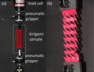
Fabrication. Specimens are fabricated by laser cutting an array of mutually perpendicular cuts into plastic sheets (Artus Corporation, NJ). Total number of 10 samples are fabricated with a combination of different sheet thickness (m, m, m and m) and three normalized hinge widths (). Note that in all our samples mm. The material properties of the plastic sheets used in this study are characterized by performing uniaxial tensile tests (ASTM D882) with a uniaxial testing machine (Instron 5566) equipped with a 100N load cell. Strips with a width of 10 mm and gauge length of 120 mm are fully clamped at both ends using a pneumatic gripper and stretched with a displacement rate of 0.1 mm/s up to [Fig. S3]. The stress-strain curves reported in Fig. S3 indicate that the polyester sheets with thickness m (red line), m (green line), m (blue line) are characterized by a Young’s modulus GPa. Moreover, their 0.2% offset yield strength is measured as MPa and their plastic strain versus is reported in the Table S1 up to fully plastic region. Differently, for the thick PETG sheet (m, yellow line) we measure a Young’s modulus GPa. Finally, we note that for all the plastic sheets a typical Poisson’s ratio is assumed.
| 0 | 0.002 | 0.004 | 0.006 | 0.008 | 0.018 | 0.028 | |
|---|---|---|---|---|---|---|---|
| (MPa) | 66.4 | 75.78 | 80.52 | 82.75 | 84.45 | 88.09 | 89.06 |
Testing. The quasi-static uniaxial tensile response of the perforated sheets comprised of unit cells was probed by using a uniaxial testing machine (Instron 5566) equipped with a 10N load cell. All test were conducted under displacement rate of mm/s [Fig. S4].
I.3 Finite Element simulations
In this Section, we provide details about the Finite Element (FE) simulations conducted for this study using the commercial package Abaqus\Standard 6.12 (Dassault Systèmes). In all simulations, the models are discretized with 3D shell elements (S4R) and the cuts in flat sheets are modeled as seam cracks with duplicate overlapping nodes along the cuts.
Finite size simulations. To validate the FE simulations, we first performed finite size simulations on perforated sheets similar to those used in experiments comprising an array of cells. The lower boundary of the sample is fixed and a vertical displacement is applied to the upper boundary while the lateral boundaries are assumed to be traction free. The material behavior of the plastic sheet is captured using an elasto-plastic model (material models *ELASTIC and *PLASTIC in Abaqus) with the experimentally characterized properties (see Fig. S3 and Table S1). The response of the sheets is then simulated conducting dynamic implicit simulations (*DYNAMIC module in Abaqus). To facilitate convergence, we introduce some artificial, numerical damping (by setting the parameters , and in the Hilber-Hughes-Taylor time integration algorithm). Moreover, quasi-static conditions are ensured by monitoring the kinetic energy and finally, to trigger the instability an imperfection is introduced by applying two opposing small bias forces normal to the sheet plane at two ends of each cut during the initial phase of each simulation.

First, we numerically investigate the response of finite size samples stretched along the square diagonals (i.e. ) and find excellent agreement with the experimental results (Fig. S5 and Movie 2). This validates the numerical analyses and indicates that they can be effectively used to explore the response of the system. Moreover, the simulations provide additional insights, since they allow us to easily monitor the stress distribution within the sheets and, therefore, to understand how plastic deformation evolves. In Fig. S6 we show a close-up view of the distribution of von Mises stress, , at the hinges located in the middle of a finite size sample characterized by (mm and m) for . Since for the material considered in this study plastic deformation develops when MPa (see Fig. S3 and Table S1), the snapshots indicate that yielding at the hinges initiate at . Note that, although this is a very small value of strain, it is well beyond the onset of buckling (for this sample ). We then find that the plastic zone at the hinges gradually increase with the applied strain and fully cover them when the sample is fully stretched and the deformation mechanism of the hinges changes from bending-dominated to stretching-dominated.
Second, we use FE to explore the effect of different loading conditions. More specifically, while in the main text we focus exclusively on perforated sheets subjected to uniaxial tension, here we investigate the response of a perforated sheet characterized by and and under biaxial deformation applied at . We perform simulations on a finite size sample comprising unit cells and consider three load cases: () equibiaxial tension (i.e. ), () equibiaxial compression (i.e. ) and () biaxial tension/compression (i.e. ). For all cases appropriate displacements in the - plane are applied to all nodes on the edges of the models, while constraining their displacements in -direction (note that all rotations are left unset).
Our simulations indicate that under equibiaxial tension the structure remains roughly flat and no out-of-plane pattern emerges [see Fig. S7(a)]. This is because, as indicated by the Poisson’s ratio results reported in Fig. 4(b) of the main text, the formation of the out-of-plane pattern is accompanied by lateral contraction and under equibiaxial tension such contraction is prevented by the tensile stretch applied in the transverse direction. Moreover, as shown in Fig. S7(b), we find that under equibiaxial compression the periodic pattern of cuts does not significantly affect the response of the system. Our perforated sheet behaves similarly to a continuous thin sheet and buckles out of plane to form a dome-like shape. Finally, for the case of biaxial tension/compression our simulations show that the response of the perforated sheets is very similar to that observed under uniaxial tension [see Fig. S7(c)]. This is because, differently from the case of equibiaxial tension, for this loading condition the compressive stretch applied in lateral direction favors the formation of the out-of-plane pattern. However, it is important to note that in the case of biaxial tension/compression the response of the sheets is highly affected by their size. For sheets with larger number of unit cell aligned in the direction of the applied compressive force we find that the sheet buckles globally to form a wavy pattern. Therefore, this set of simulations indicate that uniaxial tension is the ideal loading condition to trigger the formation of well-organized out-of-plane patterns in our perforated sheets.
Unit cell simulations. To reduce the computational costs and make sure the response of the system is not dominated by boundary effects, we investigate the response of infinite perforated sheets under periodic boundary conditions. Since here we are mostly interested in the response of the perforated sheet immediately after buckling (i.e. before the plastic deformation takes place), for this set of simulations we use a linear elastic material model (with GPa and ). All simulations consist of two steps: () we first use a linear perturbation analysis (*BUCKLE module in Abaqus) to identify the critical buckling mode; () we then introduce a small imperfection () in the form of the critical mode into the mesh to guide the post-buckling analysis. As for the finite size simulations, for this step we conduct dynamic implicit simulations (*DYNAMIC module in Abaqus) and to facilitate convergence, we introduce some artificial, numerical damping.
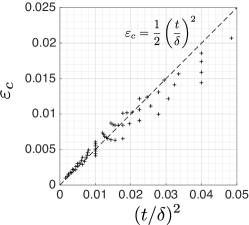
In Fig. S8 we compare the analytical expression for the critical strain [Eq. (S21)] with the numerical predictions of 54 unit cell simulations characterized by and and . We find an excellent agreement between numerical (markers) and analytical (dashed line) results.
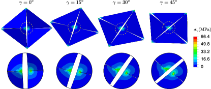
Finally, in Fig. S9 we show the von Mises stress distribution in a unit cell characterized by and for different values of at . As expected, we find that the von Mises stress, , is maximum at the hinges. Assuming the sheets are made of the same material used to fabricate our sample (i.e. with GPa and ), we also find that in all unit cells MPa. This is the stress at which we expect plastic deformation to initiate for the considered material (see Fig. S3 and Table S1). Therefore, we can conclude that the yielding of the hinges begins approximately at . Since, this strain is more than twice the critical strain (i.e. ), these simulations confirm that no plastic deformation takes place before buckling.
I.4 Movie captions
Movie 1 Buckling-induced 3D kirigami in thin perforated sheets.
In sufficiently thin sheets perforated with a square array of mutually orthogonal cuts mechanical instabilities are triggered under uniaxial tension and can be exploited to create complex 3D patterns. If the sheet is loaded along the square diagonals (i.e. ), a 3D pattern reminiscent of a misaligned Miura-ori emerges, while loading along one set of the cuts (i.e. ) results in a 3D cubic pattern.
Movie 2 Uniaxial loading: Experiment vs FE simulation.
The deformation of perforated sheets subjected to uniaxial tensile loading along the square diagonals () can be accurately captured by FE simulations in Abaqus.
Movie 3 Buckling-induced Miura kirigami .
Although we start with a flat elastic sheet with an embedded array of cuts, by largely stretching it we end up with a system that comprises a periodic arrangement of both cuts and folds. As a result, after being fully stretched our sheets possess several deformation characteristics of the Miura-ori, including flat-foldability, negative Gaussian curvature under non-planar bending and twisting under anti-symmetric out-of-plane deformation.
Miura kirigami also exhibits an enhanced bending rigidity compared to a flat perforated sheet.
Movie 4 In-plane Poisson’s ratio of buckling-induced kirigami.
In contrast to Miura-ori and misaligned Miura-ori, the in-plane Poisson’s ratio of our perforated sheets after buckling is positive.
Movie 5 Buckling-induced cubic kirigami.
The kirigami structure obtained by fully stretching the perforated sheet along one set of the cuts (i.e. ) is () flat foldable, () exhibits a zero Gaussian curvature under non-planar bending and () has relatively higher torsional rigidity compared to that of the structure obtained by loading the sheet along the diagonals of the squares (i.e. ).
Movie 6 Comparing the behavior of kirigami sheets.
Permanent folds with direction controlled by can be introduced by largely stretching the perforated sheets. As such, by controlling the loading direction a variety of kirigami sheets can be formed. While all of them are laterally flat-foldable, we find that by increasing from to the resulting kirigami sheets have higher bending rigidity and their Gaussian curvature varies from zero (for ) to large negative values (for ). Furthermore, by increasing , the resulting kirigami sheets become more compliant under torsion.