Dual combination combination multi switching synchronization of eight chaotic systems

Ayub Khan Dinesh Khattar Nitish Prajapati nitishprajapati499@gmail.com Department of Mathematics, Jamia Millia Islamia, Delhi, India. Department of Mathematics, Kirorimal College, University of Delhi, Delhi, India. Department of Mathematics, University of Delhi, Delhi, India.
Abstract

In this paper, a novel scheme for synchronizing four drive and four response systems is proposed by the authors. The idea of multi switching and dual combination synchronization is extended to dual combination-combination multi switching synchronization involving eight chaotic systems and is a first of its kind. Due to the multiple combination of chaotic systems and multi switching the resultant dynamic behaviour is so complex that, in communication theory, transmission and security of the resultant signal is more effective. Using Lyapunov stability theory, sufficient conditions are achieved and suitable controllers are designed to realise the desired synchronization. Corresponding theoretical analysis is presented and numerical simulations performed to demonstrate the effectiveness of the proposed scheme.

keywords:
Chaos synchronization , multi switching synchronization , combination combination synchronization , dual synchronization , nonlinear control

1 Introduction

Much has been written and said about the concept of synchronization of chaotic systems since it was first introduced by Pecora and Caroll [1]. Because of its interdisciplinary nature the chaos synchronization problem has received interest from researchers across the academic fields such as physics, mathematics, engineering, biology, chemistry, etc. The potential applications of chaos synchronization to engineering systems, information processing, secure communications, and biomedical science amongst many others has led to a vast variety of research studies in this topic of nonlinear science [2, 3, 4, 5]. Various kinds of synchronization such as complete synchronization, anti synchronization, projective synchronization, reduced order synchronization, etc. have been reported and presented in a variety of chaotic systems using many effective methods such as active control, adaptive control, backstepping control, sliding mode control and so on [6, 7, 8, 9, 10, 11, 12, 13].

Amongst many synchronization schemes, dual synchronization of chaotic systems is one which has successfully piqued the scientific curiosity of researchers because of its challenging and non traditional nature. Deviating from the traditional approach of synchronizing one drive and one response system, in dual synchronization two drive systems are synchronized with two response systems. Since the first inception of the idea by Liu and Davids [14], it has been extensively investigated in various synchronization studies [15, 16, 17]. In all prior work the common theme is to consider one pair of drive system with one pair of response system. Only recently the idea of dual synchronization was extended to two pair of drive systems and one pair of response system [18, 19].

Synchronization studies involving multiple drive and response systems is a relatively unexplored area of research. New ideas have recently been initiated in the study of chaos synchronization where multiple chaotic systems are involved. In the literature of chaos synchronization the addition of combination synchronization [20, 21], combination combination synchronization [22, 23], compound synchronization [24, 25], double compound synchronization [26], compound combination synchronization [27, 28] etc. has opened new research directions to be explored. These significant ideas have strengthened the security of information transmission because of the complexity which they bring in transmitted signals.

Multi switching synchronization of chaotic systems is yet another relatively unexplored area of research [29]. In this non conventional scheme, different states of the drive system are synchronized with different state of the response system. Due to this, a wide range of synchronization direction exists for multi switching synchronization schemes. The importance of such kind of studies to information security cannot be emphasised enough and thus makes them a very relevant topic to be investigated. A few reported work in this direction can be studied in [30, 31, 32, 33]. To the knowledge of authors the diverse possibilities of multi switching synchronization have not yet been explored with the dual synchronization schemes.

In this paper, motivated by the above discussion, the authors have combined the idea of multi switching with dual synchronization and extended it to combination combination synchronization of four chaotic systems. The novel scheme, dual combination combination multi switching synchronization involves eight chaotic systems of which four are drive systems and four are response systems. In contrast to double compound synchronization involving four drive and two response systems, this work is a significant improvement and extension. Using Lyapunov stability theory, sufficient conditions have been achieved to realise the desired synchronization. To demonstrate the effectiveness of the proposed method numerical simulations have been performed. The main contribution and advantages of this study are: a) The dual synchronization study has been extended to pair of two drive and two response systems to achieve dual combination combination synchronization. no such work involving two pair of response systems has earlier been reported. b) The multi switching synchronization scheme is combined with dual combination combination synchronization to achieve the novel scheme which is a first of its kind. No previous work on dual multi switching studies exist. c) The proposed scheme successfully synchronizes eight chaotic systems of which four are drive and four are response systems. The complexity of signals due to multiple combination and the number of synchronization directions due to multi switching vastly enhances the anti attack ability of any signal that will be transmitted using combination of two pair of drive systems. d) Several existing synchronization schemes are obtained as special cases of dual combination combination multi switching synchronization.

2 Formulation of dual combination combination multi switching synchronization

In this section, we formulate the scheme of DCCMS of chaotic systems. We require two pair of four chaotic drive systems and two pair of four chaotic response systems. Let the first two drive systems be described as

x1˙=f1(x1)˙subscript𝑥1subscript𝑓1subscript𝑥1\dot{x_{1}}=f_{1}(x_{1}) (1)
x2˙=f2(x2)˙subscript𝑥2subscript𝑓2subscript𝑥2\dot{x_{2}}=f_{2}(x_{2}) (2)

where x1=(x11,x12,,x1n)Tsubscript𝑥1superscriptsubscript𝑥11subscript𝑥12subscript𝑥1𝑛𝑇x_{1}=(x_{11},x_{12},...,x_{1n})^{T}, x2=(x21,x22,,x2n)Tsubscript𝑥2superscriptsubscript𝑥21subscript𝑥22subscript𝑥2𝑛𝑇x_{2}=(x_{21},x_{22},...,x_{2n})^{T}, f1subscript𝑓1f_{1}, f2subscript𝑓2f_{2}: RnRnsuperscript𝑅𝑛superscript𝑅𝑛R^{n}\rightarrow R^{n} are known continuous vector functions. Linear combination of the states of two drive systems (1) and (2) gives a resultant signal of the form

S1=subscript𝑆1absent\displaystyle S_{1}= [a11x11,a12x12,,a1nx1n,a21x21,a22x22,,a2nx2n]Tsuperscriptsubscript𝑎11subscript𝑥11subscript𝑎12subscript𝑥12subscript𝑎1𝑛subscript𝑥1𝑛subscript𝑎21subscript𝑥21subscript𝑎22subscript𝑥22subscript𝑎2𝑛subscript𝑥2𝑛𝑇\displaystyle[a_{11}x_{11},a_{12}x_{12},...,a_{1n}x_{1n},a_{21}x_{21},a_{22}x_{22},...,a_{2n}x_{2n}]^{T} (3)
=\displaystyle= [A100A2][x1x2]=Axmatrixsubscript𝐴100subscript𝐴2matrixsubscript𝑥1subscript𝑥2𝐴𝑥\displaystyle\begin{bmatrix}A_{1}&0\\ 0&A_{2}\\ \end{bmatrix}\begin{bmatrix}x_{1}\\ x_{2}\\ \end{bmatrix}=Ax

where A1=diag(a11,a12,,a1n)subscript𝐴1𝑑𝑖𝑎𝑔subscript𝑎11subscript𝑎12subscript𝑎1𝑛A_{1}=diag(a_{11},a_{12},...,a_{1n}), and A2=diag(a21,a22,,a2n)subscript𝐴2𝑑𝑖𝑎𝑔subscript𝑎21subscript𝑎22subscript𝑎2𝑛A_{2}=diag(a_{21},a_{22},...,a_{2n}) are two known matrices and a1i,a2jsubscript𝑎1𝑖subscript𝑎2𝑗a_{1i},a_{2j} are not all zero at the same time (i,j=1,2,,n)formulae-sequence𝑖𝑗12𝑛(i,j=1,2,...,n).

Next two drive systems are written as

y1˙=g1(y1)˙subscript𝑦1subscript𝑔1subscript𝑦1\dot{y_{1}}=g_{1}(y_{1}) (4)
y2˙=g2(y2)˙subscript𝑦2subscript𝑔2subscript𝑦2\dot{y_{2}}=g_{2}(y_{2}) (5)

where y1=(y11,y12,,y1n)Tsubscript𝑦1superscriptsubscript𝑦11subscript𝑦12subscript𝑦1𝑛𝑇y_{1}=(y_{11},y_{12},...,y_{1n})^{T}, y2=(y21,y22,,y2n)Tsubscript𝑦2superscriptsubscript𝑦21subscript𝑦22subscript𝑦2𝑛𝑇y_{2}=(y_{21},y_{22},...,y_{2n})^{T}, g1subscript𝑔1g_{1}, g2subscript𝑔2g_{2}: RnRnsuperscript𝑅𝑛superscript𝑅𝑛R^{n}\rightarrow R^{n} are known continuous vector functions. Hence, the linear combination of the states of two drive systems (4) and (5) gives a resultant signal of the form

S2=subscript𝑆2absent\displaystyle S_{2}= [b11y11,b12y12,,b1ny1n,b21y21,b22y22,,b2ny2n]Tsuperscriptsubscript𝑏11subscript𝑦11subscript𝑏12subscript𝑦12subscript𝑏1𝑛subscript𝑦1𝑛subscript𝑏21subscript𝑦21subscript𝑏22subscript𝑦22subscript𝑏2𝑛subscript𝑦2𝑛𝑇\displaystyle[b_{11}y_{11},b_{12}y_{12},...,b_{1n}y_{1n},b_{21}y_{21},b_{22}y_{22},...,b_{2n}y_{2n}]^{T} (6)
=\displaystyle= [B100B2][y1y2]=Bymatrixsubscript𝐵100subscript𝐵2matrixsubscript𝑦1subscript𝑦2𝐵𝑦\displaystyle\begin{bmatrix}B_{1}&0\\ 0&B_{2}\\ \end{bmatrix}\begin{bmatrix}y_{1}\\ y_{2}\\ \end{bmatrix}=By

where B1=diag(b11,b12,,b1n)subscript𝐵1𝑑𝑖𝑎𝑔subscript𝑏11subscript𝑏12subscript𝑏1𝑛B_{1}=diag(b_{11},b_{12},...,b_{1n}), and B2=diag(b21,b22,,b2n)subscript𝐵2𝑑𝑖𝑎𝑔subscript𝑏21subscript𝑏22subscript𝑏2𝑛B_{2}=diag(b_{21},b_{22},...,b_{2n}) are two known matrices and b1i,b2jsubscript𝑏1𝑖subscript𝑏2𝑗b_{1i},b_{2j} are not all zero at the same time (i,j=1,2,,n)formulae-sequence𝑖𝑗12𝑛(i,j=1,2,...,n).

Let the first two response systems be given by

z1˙=h1(z1)+u1˙subscript𝑧1subscript1subscript𝑧1subscript𝑢1\dot{z_{1}}=h_{1}(z_{1})+u_{1} (7)
z2˙=h2(z2)+u2˙subscript𝑧2subscript2subscript𝑧2subscript𝑢2\dot{z_{2}}=h_{2}(z_{2})+u_{2} (8)

where z1=(z11,z12,,z1n)Tsubscript𝑧1superscriptsubscript𝑧11subscript𝑧12subscript𝑧1𝑛𝑇z_{1}=(z_{11},z_{12},...,z_{1n})^{T}, z2=(z21,z22,,z2n)Tsubscript𝑧2superscriptsubscript𝑧21subscript𝑧22subscript𝑧2𝑛𝑇z_{2}=(z_{21},z_{22},...,z_{2n})^{T}, h1subscript1h_{1}, h2subscript2h_{2}: RnRnsuperscript𝑅𝑛superscript𝑅𝑛R^{n}\rightarrow R^{n} are known continuous vector functions, and u1=(u11,u12,,u1n)subscript𝑢1subscript𝑢11subscript𝑢12subscript𝑢1𝑛u_{1}=(u_{11},u_{12},...,u_{1n}), u2=(u21,u22,,u2n)subscript𝑢2subscript𝑢21subscript𝑢22subscript𝑢2𝑛u_{2}=(u_{21},u_{22},...,u_{2n}) are the controllers to be designed. By linear combination of the states of two response systems (7) and (8) a resultant signal is obtained of the form

S3=subscript𝑆3absent\displaystyle S_{3}= [c11z11,c12z12,,c1nz1n,c21z21,c22z22,,c2nz2n]Tsuperscriptsubscript𝑐11subscript𝑧11subscript𝑐12subscript𝑧12subscript𝑐1𝑛subscript𝑧1𝑛subscript𝑐21subscript𝑧21subscript𝑐22subscript𝑧22subscript𝑐2𝑛subscript𝑧2𝑛𝑇\displaystyle[c_{11}z_{11},c_{12}z_{12},...,c_{1n}z_{1n},c_{21}z_{21},c_{22}z_{22},...,c_{2n}z_{2n}]^{T} (9)
=\displaystyle= [C100C2][z1z2]=Czmatrixsubscript𝐶100subscript𝐶2matrixsubscript𝑧1subscript𝑧2𝐶𝑧\displaystyle\begin{bmatrix}C_{1}&0\\ 0&C_{2}\\ \end{bmatrix}\begin{bmatrix}z_{1}\\ z_{2}\\ \end{bmatrix}=Cz

where C1=diag(c11,c12,,c1n)subscript𝐶1𝑑𝑖𝑎𝑔subscript𝑐11subscript𝑐12subscript𝑐1𝑛C_{1}=diag(c_{11},c_{12},...,c_{1n}), and C2=diag(c21,c22,,c2n)subscript𝐶2𝑑𝑖𝑎𝑔subscript𝑐21subscript𝑐22subscript𝑐2𝑛C_{2}=diag(c_{21},c_{22},...,c_{2n}) are two known matrices and c1i,c2jsubscript𝑐1𝑖subscript𝑐2𝑗c_{1i},c_{2j} are not all zero simultaneously (i,j=1,2,,n)formulae-sequence𝑖𝑗12𝑛(i,j=1,2,...,n).

Let the next two response systems be described as

w1˙=k1(w1)+u3˙subscript𝑤1subscript𝑘1subscript𝑤1subscript𝑢3\dot{w_{1}}=k_{1}(w_{1})+u_{3} (10)
w2˙=k2(w2)+u4˙subscript𝑤2subscript𝑘2subscript𝑤2subscript𝑢4\dot{w_{2}}=k_{2}(w_{2})+u_{4} (11)

where w1=(w11,w12,,w1n)Tsubscript𝑤1superscriptsubscript𝑤11subscript𝑤12subscript𝑤1𝑛𝑇w_{1}=(w_{11},w_{12},...,w_{1n})^{T}, w2=(w21,w22,,w2n)Tsubscript𝑤2superscriptsubscript𝑤21subscript𝑤22subscript𝑤2𝑛𝑇w_{2}=(w_{21},w_{22},...,w_{2n})^{T}, k1subscript𝑘1k_{1}, k2subscript𝑘2k_{2}: RnRnsuperscript𝑅𝑛superscript𝑅𝑛R^{n}\rightarrow R^{n} are known continuous vector functions, and u3=(u31,u32,,u3n)subscript𝑢3subscript𝑢31subscript𝑢32subscript𝑢3𝑛u_{3}=(u_{31},u_{32},...,u_{3n}), u4=(u41,u42,,u4n)subscript𝑢4subscript𝑢41subscript𝑢42subscript𝑢4𝑛u_{4}=(u_{41},u_{42},...,u_{4n}) are the controllers to be designed. Linear combination of the states of two response systems (10) and (11) gives a resultant signal of the form

S4=subscript𝑆4absent\displaystyle S_{4}= [d11z11,d12z12,,d1nz1n,d21z21,d22z22,,d2nz2n]Tsuperscriptsubscript𝑑11subscript𝑧11subscript𝑑12subscript𝑧12subscript𝑑1𝑛subscript𝑧1𝑛subscript𝑑21subscript𝑧21subscript𝑑22subscript𝑧22subscript𝑑2𝑛subscript𝑧2𝑛𝑇\displaystyle[d_{11}z_{11},d_{12}z_{12},...,d_{1n}z_{1n},d_{21}z_{21},d_{22}z_{22},...,d_{2n}z_{2n}]^{T} (12)
=\displaystyle= [D100D2][z1z2]=Dzmatrixsubscript𝐷100subscript𝐷2matrixsubscript𝑧1subscript𝑧2𝐷𝑧\displaystyle\begin{bmatrix}D_{1}&0\\ 0&D_{2}\\ \end{bmatrix}\begin{bmatrix}z_{1}\\ z_{2}\\ \end{bmatrix}=Dz

where D1=diag(d11,d12,,d1n)subscript𝐷1𝑑𝑖𝑎𝑔subscript𝑑11subscript𝑑12subscript𝑑1𝑛D_{1}=diag(d_{11},d_{12},...,d_{1n}), and D2=diag(d21,d22,,d2n)subscript𝐷2𝑑𝑖𝑎𝑔subscript𝑑21subscript𝑑22subscript𝑑2𝑛D_{2}=diag(d_{21},d_{22},...,d_{2n}) are two known matrices and d1i,d2jsubscript𝑑1𝑖subscript𝑑2𝑗d_{1i},d_{2j} are not all zero at the same time (i,j=1,2,,n)formulae-sequence𝑖𝑗12𝑛(i,j=1,2,...,n).

The error signal for dual combination combination synchronization is

e=𝑒absent\displaystyle e= S1+S2S3S4subscript𝑆1subscript𝑆2subscript𝑆3subscript𝑆4\displaystyle S_{1}+S_{2}-S_{3}-S_{4} (13)
=\displaystyle= Ax+ByCzDw𝐴𝑥𝐵𝑦𝐶𝑧𝐷𝑤\displaystyle Ax+By-Cz-Dw
=\displaystyle= [A100A2][x1x2]+[B100B2][y1y2][C100C2][z1z2][D100D2][w1w2]matrixsubscript𝐴100subscript𝐴2matrixsubscript𝑥1subscript𝑥2matrixsubscript𝐵100subscript𝐵2matrixsubscript𝑦1subscript𝑦2matrixsubscript𝐶100subscript𝐶2matrixsubscript𝑧1subscript𝑧2matrixsubscript𝐷100subscript𝐷2matrixsubscript𝑤1subscript𝑤2\displaystyle\begin{bmatrix}A_{1}&0\\ 0&A_{2}\\ \end{bmatrix}\begin{bmatrix}x_{1}\\ x_{2}\\ \end{bmatrix}+\begin{bmatrix}B_{1}&0\\ 0&B_{2}\\ \end{bmatrix}\begin{bmatrix}y_{1}\\ y_{2}\\ \end{bmatrix}-\begin{bmatrix}C_{1}&0\\ 0&C_{2}\\ \end{bmatrix}\begin{bmatrix}z_{1}\\ z_{2}\\ \end{bmatrix}-\begin{bmatrix}D_{1}&0\\ 0&D_{2}\\ \end{bmatrix}\begin{bmatrix}w_{1}\\ w_{2}\\ \end{bmatrix}
=\displaystyle= [A1x1+B1y1C1z1D1w1A2x2+B2y2C2z2D2w2]matrixsubscript𝐴1subscript𝑥1subscript𝐵1subscript𝑦1subscript𝐶1subscript𝑧1subscript𝐷1subscript𝑤1subscript𝐴2subscript𝑥2subscript𝐵2subscript𝑦2subscript𝐶2subscript𝑧2subscript𝐷2subscript𝑤2\displaystyle\begin{bmatrix}A_{1}x_{1}+B_{1}y_{1}-C_{1}z_{1}-D_{1}w_{1}\\ A_{2}x_{2}+B_{2}y_{2}-C_{2}z_{2}-D_{2}w_{2}\\ \end{bmatrix}
Definition 1.

If there exist four constant diagonal matrices A,B,C,DR2n×2n𝐴𝐵𝐶𝐷superscript𝑅2𝑛2𝑛A,B,C,D\in R^{2n\times 2n} and C0𝐶0C\neq 0 or D0𝐷0D\neq 0 such that

limte=limtAx+ByCzDw=0,subscript𝑡norm𝑒subscript𝑡norm𝐴𝑥𝐵𝑦𝐶𝑧𝐷𝑤0\lim_{t\to\infty}\|e\|=\lim_{t\to\infty}\|Ax+By-Cz-Dw\|=0, (14)

where .\|.\| is the vector norm, then the drive systems (1), (2), (4), and (5) realise dual combination combination synchronization with the response systems (7), (8), (10), and (11).

Remark 1.

The diagonal matrices A𝐴A, B𝐵B, C𝐶C, and D𝐷D are called the scaling matrices and can be extended to functional matrices of state variables x𝑥x, y𝑦y, z𝑧z, and w𝑤w.

Comment 1.

From (14) we get that dual combination combination synchronization is achieved when

limte=limtAx+ByCzDw=0,subscript𝑡norm𝑒subscript𝑡norm𝐴𝑥𝐵𝑦𝐶𝑧𝐷𝑤0\lim_{t\to\infty}\|e\|=\lim_{t\to\infty}\|Ax+By-Cz-Dw\|=0,

which is equivalent to say that

limte1=subscript𝑡normsubscript𝑒1absent\displaystyle\lim_{t\to\infty}\|e_{1}\|= limtA1x1+B1y1C1z1D1w1=0subscript𝑡normsubscript𝐴1subscript𝑥1subscript𝐵1subscript𝑦1subscript𝐶1subscript𝑧1subscript𝐷1subscript𝑤10\displaystyle\lim_{t\to\infty}\|A_{1}x_{1}+B_{1}y_{1}-C_{1}z_{1}-D_{1}w_{1}\|=0
limte2=subscript𝑡normsubscript𝑒2absent\displaystyle\lim_{t\to\infty}\|e_{2}\|= limtA2x2+B2y2C2z2D2w2=0subscript𝑡normsubscript𝐴2subscript𝑥2subscript𝐵2subscript𝑦2subscript𝐶2subscript𝑧2subscript𝐷2subscript𝑤20\displaystyle\lim_{t\to\infty}\|A_{2}x_{2}+B_{2}y_{2}-C_{2}z_{2}-D_{2}w_{2}\|=0

where e=(e1,e2)T𝑒superscriptsubscript𝑒1subscript𝑒2𝑇e=(e_{1},e_{2})^{T}. This can be further written as

limte1m=subscript𝑡subscript𝑒1𝑚absent\displaystyle\lim_{t\to\infty}e_{1m}= limta1mx1m+b1my1mc1mz1md1mw1m=0subscript𝑡subscript𝑎1𝑚subscript𝑥1𝑚subscript𝑏1𝑚subscript𝑦1𝑚subscript𝑐1𝑚subscript𝑧1𝑚subscript𝑑1𝑚subscript𝑤1𝑚0\displaystyle\lim_{t\to\infty}a_{1m}x_{1m}+b_{1m}y_{1m}-c_{1m}z_{1m}-d_{1m}w_{1m}=0
limte2m=subscript𝑡subscript𝑒2𝑚absent\displaystyle\lim_{t\to\infty}e_{2m}= limta2mx2m+b2my2mc2mz2md2mw2m=0subscript𝑡subscript𝑎2𝑚subscript𝑥2𝑚subscript𝑏2𝑚subscript𝑦2𝑚subscript𝑐2𝑚subscript𝑧2𝑚subscript𝑑2𝑚subscript𝑤2𝑚0\displaystyle\lim_{t\to\infty}a_{2m}x_{2m}+b_{2m}y_{2m}-c_{2m}z_{2m}-d_{2m}w_{2m}=0

where e1=(e11,e12,,e1n)subscript𝑒1subscript𝑒11subscript𝑒12subscript𝑒1𝑛e_{1}=(e_{11},e_{12},...,e_{1n}), e2=(e21,e22,,e2n)subscript𝑒2subscript𝑒21subscript𝑒22subscript𝑒2𝑛e_{2}=(e_{21},e_{22},...,e_{2n}), and m=1,2,,n𝑚12𝑛m=1,2,...,n.

Comment 2.

Let us rewrite the components of e1subscript𝑒1e_{1}, and e2subscript𝑒2e_{2} as

{e1m(ijlm)=a1ix1i+b1jy1jc1lz1ld1mw1me2m(ijlm)=a2ix2i+b2jy2jc2lz2ld2mw2m\left\{\begin{aligned} e_{1m_{(ijlm)}}=a_{1i}x_{1i}+b_{1j}y_{1j}-c_{1l}z_{1l}-d_{1m}w_{1m}\\ e_{2m_{(ijlm)}}=a_{2i}x_{2i}+b_{2j}y_{2j}-c_{2l}z_{2l}-d_{2m}w_{2m}\\ \end{aligned}\right. (15)

where i,j,l,m=1,2,,nformulae-sequence𝑖𝑗𝑙𝑚12𝑛i,j,l,m=1,2,...,n and the subscript (ijlm)𝑖𝑗𝑙𝑚(ijlm) denotes ithsuperscript𝑖𝑡i^{th} component of x1subscript𝑥1x_{1} and x2subscript𝑥2x_{2}, jthsuperscript𝑗𝑡j^{th} component of y1subscript𝑦1y_{1} and y2subscript𝑦2y_{2}, lthsuperscript𝑙𝑡l^{th} component of z1subscript𝑧1z_{1} and z2subscript𝑧2z_{2}, and mthsuperscript𝑚𝑡m^{th} component of w1subscript𝑤1w_{1} and w2subscript𝑤2w_{2}. In relation to Definition 1, the indices (ijlm)𝑖𝑗𝑙𝑚(ijlm) of the error states e1m(ijlm)subscript𝑒1subscript𝑚𝑖𝑗𝑙𝑚e_{1m_{(ijlm)}}, and e2m(ijlm)subscript𝑒2subscript𝑚𝑖𝑗𝑙𝑚e_{2m_{(ijlm)}} are strictly chosen to satisfy i=j=l=m𝑖𝑗𝑙𝑚i=j=l=m (i,j,l,m=1,2,,n)formulae-sequence𝑖𝑗𝑙𝑚12𝑛(i,j,l,m=1,2,...,n).

Definition 2.

If the indices of the error states e1m(ijlm)subscript𝑒1subscript𝑚𝑖𝑗𝑙𝑚e_{1m_{(ijlm)}}, and e2m(ijlm)subscript𝑒2subscript𝑚𝑖𝑗𝑙𝑚e_{2m_{(ijlm)}} are redefined such that i=j=lm𝑖𝑗𝑙𝑚i=j=l\neq m or i=j=ml𝑖𝑗𝑚𝑙i=j=m\neq l or i=l=mj𝑖𝑙𝑚𝑗i=l=m\neq j or j=l=mi𝑗𝑙𝑚𝑖j=l=m\neq i; or i=jl=m𝑖𝑗𝑙𝑚i=j\neq l=m or i=lj=m𝑖𝑙𝑗𝑚i=l\neq j=m or i=mj=l𝑖𝑚𝑗𝑙i=m\neq j=l; or i=jlm𝑖𝑗𝑙𝑚i=j\neq l\neq m or i=ljm𝑖𝑙𝑗𝑚i=l\neq j\neq m or i=mlj𝑖𝑚𝑙𝑗i=m\neq l\neq j or ij=lm𝑖𝑗𝑙𝑚i\neq j=l\neq m or ijl=m𝑖𝑗𝑙𝑚i\neq j\neq l=m or ilj=m𝑖𝑙𝑗𝑚i\neq l\neq j=m; or ijlm𝑖𝑗𝑙𝑚i\neq j\neq l\neq m and

limte=limtAx+ByCzDw=0,subscript𝑡norm𝑒subscript𝑡norm𝐴𝑥𝐵𝑦𝐶𝑧𝐷𝑤0\lim_{t\to\infty}\|e\|=\lim_{t\to\infty}\|Ax+By-Cz-Dw\|=0, (16)

where i,j,l,m=1,2,,nformulae-sequence𝑖𝑗𝑙𝑚12𝑛i,j,l,m=1,2,...,n and .\|.\| is the vector norm, then the drive systems (1), (2), (4), and (5) are said to be in dual combination combination multi switching synchronization with response systems (7), (8), (10), and (11).

Remark 2.

If A1=B1=C1=D1=0subscript𝐴1subscript𝐵1subscript𝐶1subscript𝐷10A_{1}=B_{1}=C_{1}=D_{1}=0, or A2=B2=C2=D2=0subscript𝐴2subscript𝐵2subscript𝐶2subscript𝐷20A_{2}=B_{2}=C_{2}=D_{2}=0, then dual combination combination multi switching synchronization changes to multi switching combination combination synchronization problem of chaotic systems.

Remark 3.

If C1=C2=0subscript𝐶1subscript𝐶20C_{1}=C_{2}=0, or D1=D2=0subscript𝐷1subscript𝐷20D_{1}=D_{2}=0, then dual combination combination multi switching synchronization changes to dual combination multi switching synchronization of chaotic systems.

Remark 4.

If A1=B1=C1=D1=0subscript𝐴1subscript𝐵1subscript𝐶1subscript𝐷10A_{1}=B_{1}=C_{1}=D_{1}=0, and C2=0subscript𝐶20C_{2}=0 or D2=0subscript𝐷20D_{2}=0, or A2=B2=C2=D2=0subscript𝐴2subscript𝐵2subscript𝐶2subscript𝐷20A_{2}=B_{2}=C_{2}=D_{2}=0, and C1=0subscript𝐶10C_{1}=0 or D1=0subscript𝐷10D_{1}=0, then dual combination combination multi switching synchronization changes to multi switching combination synchronization of chaotic systems.

Remark 5.

Using suitable values for the scaling factors A1subscript𝐴1A_{1}, A2subscript𝐴2A_{2}, B1subscript𝐵1B_{1}, B2subscript𝐵2B_{2}, C1subscript𝐶1C_{1}, C2subscript𝐶2C_{2}, D1subscript𝐷1D_{1}, and D2subscript𝐷2D_{2}, multi switching dual projective synchronization and multi switching projective synchronization may also be obtained by the proposed scheme.

3 Synchronization Theory

To achieve the dual combination combination multi switching synchronization among four chaotic drive systems and four chaotic response systems, let the control functions be defined as

{U1m=a1if1i+b1jg1jc1lh1ld1mk1m+e1m(ijlm),(i,j,l,m=1,2,,n)U2m=a2if2i+b2jg2jc2lh2ld2mk2m+e2m(ijlm),(i,j,l,m=1,2,,n)\left\{\begin{aligned} U_{1m}=a_{1i}f_{1i}+b_{1j}g_{1j}-c_{1l}h_{1l}-d_{1m}k_{1m}+e_{1m_{(ijlm)}},\quad{(i,j,l,m=1,2,...,n)}\\ U_{2m}=a_{2i}f_{2i}+b_{2j}g_{2j}-c_{2l}h_{2l}-d_{2m}k_{2m}+e_{2m_{(ijlm)}},\quad{(i,j,l,m=1,2,...,n)}\\ \end{aligned}\right. (17)

where

{U1m=c1lu1l+d1mu3m,(l,m=1,2,,n)U2m=c2lu2l+d2mu4m,(l,m=1,2,,n)\left\{\begin{aligned} U_{1m}=c_{1l}u_{1l}+d_{1m}u_{3m},\quad{(l,m=1,2,...,n)}\\ U_{2m}=c_{2l}u_{2l}+d_{2m}u_{4m},\quad{(l,m=1,2,...,n)}\\ \end{aligned}\right. (18)

and f1=(f11,f12,,f1n)Tsubscript𝑓1superscriptsubscript𝑓11subscript𝑓12subscript𝑓1𝑛𝑇f_{1}=(f_{11},f_{12},...,f_{1n})^{T}, f2=(f21,f22,,f2n)Tsubscript𝑓2superscriptsubscript𝑓21subscript𝑓22subscript𝑓2𝑛𝑇f_{2}=(f_{21},f_{22},...,f_{2n})^{T}, g1=(g11,g12,,g1n)Tsubscript𝑔1superscriptsubscript𝑔11subscript𝑔12subscript𝑔1𝑛𝑇g_{1}=(g_{11},g_{12},...,g_{1n})^{T}, g2=(g21,g22,,g2n)Tsubscript𝑔2superscriptsubscript𝑔21subscript𝑔22subscript𝑔2𝑛𝑇g_{2}=(g_{21},g_{22},...,g_{2n})^{T}, h1=(h11,h12,,h1n)Tsubscript1superscriptsubscript11subscript12subscript1𝑛𝑇h_{1}=(h_{11},h_{12},...,h_{1n})^{T}, h2=(h21,h22,,h2n)Tsubscript2superscriptsubscript21subscript22subscript2𝑛𝑇h_{2}=(h_{21},h_{22},...,h_{2n})^{T}, k1=(k11,k12,,k1n)Tsubscript𝑘1superscriptsubscript𝑘11subscript𝑘12subscript𝑘1𝑛𝑇k_{1}=(k_{11},k_{12},...,k_{1n})^{T}, and k2=(k21,k22,,k2n)Tsubscript𝑘2superscriptsubscript𝑘21subscript𝑘22subscript𝑘2𝑛𝑇k_{2}=(k_{21},k_{22},...,k_{2n})^{T}.

Theorem 1.

The drive systems (1), (2), (4), and (5) achieve dual combination combination multi switching synchronization with response systems (7), (8), (10), and (11) if the control functions are chosen as given in (17).

Proof.

Using (13) the error dynamical system can be written as

e˙=[e˙1e˙2]=[A1x˙1+B1y˙1C1z˙1D1w˙1A2x˙2+B2y˙2C2z˙2D2w˙2]˙𝑒matrixsubscript˙𝑒1subscript˙𝑒2matrixsubscript𝐴1subscript˙𝑥1subscript𝐵1subscript˙𝑦1subscript𝐶1subscript˙𝑧1subscript𝐷1subscript˙𝑤1subscript𝐴2subscript˙𝑥2subscript𝐵2subscript˙𝑦2subscript𝐶2subscript˙𝑧2subscript𝐷2subscript˙𝑤2\dot{e}=\begin{bmatrix}\dot{e}_{1}\\ \dot{e}_{2}\\ \end{bmatrix}=\begin{bmatrix}A_{1}\dot{x}_{1}+B_{1}\dot{y}_{1}-C_{1}\dot{z}_{1}-D_{1}\dot{w}_{1}\\ A_{2}\dot{x}_{2}+B_{2}\dot{y}_{2}-C_{2}\dot{z}_{2}-D_{2}\dot{w}_{2}\\ \end{bmatrix} (19)

which can be further written as

[e˙1e˙2]=[A1f1+B1g1C1(h1+u1)D1(k1+u3)A2f2+B2g2C2(h2+u2)D2(k2+u4)]matrixsubscript˙𝑒1subscript˙𝑒2matrixsubscript𝐴1subscript𝑓1subscript𝐵1subscript𝑔1subscript𝐶1subscript1subscript𝑢1subscript𝐷1subscript𝑘1subscript𝑢3subscript𝐴2subscript𝑓2subscript𝐵2subscript𝑔2subscript𝐶2subscript2subscript𝑢2subscript𝐷2subscript𝑘2subscript𝑢4\begin{bmatrix}\dot{e}_{1}\\ \dot{e}_{2}\\ \end{bmatrix}=\begin{bmatrix}A_{1}f_{1}+B_{1}g_{1}-C_{1}(h_{1}+u_{1})-D_{1}(k_{1}+u_{3})\\ A_{2}f_{2}+B_{2}g_{2}-C_{2}(h_{2}+u_{2})-D_{2}(k_{2}+u_{4})\\ \end{bmatrix} (20)

From this we obtain

{e˙1m(ijlm)=a1if1i+b1jg1jc1l(h1l+u1l)d1m(k1m+u3m),(i,j,l,m=1,2,,n)e˙2m(ijlm)=a2if2i+b2jg2jc2l(h2l+u2l)d2m(k2m+u4m),(i,j,l,m=1,2,,n)\left\{\begin{aligned} \dot{e}_{1m_{(ijlm)}}=&a_{1i}f_{1i}+b_{1j}g_{1j}-c_{1l}(h_{1l}+u_{1l})-d_{1m}(k_{1m}+u_{3m}),\\ &\quad{(i,j,l,m=1,2,...,n)}\\ \dot{e}_{2m_{(ijlm)}}=&a_{2i}f_{2i}+b_{2j}g_{2j}-c_{2l}(h_{2l}+u_{2l})-d_{2m}(k_{2m}+u_{4m}),\\ &\quad{(i,j,l,m=1,2,...,n)}\\ \end{aligned}\right. (21)

where the indices (ijlm) satisfies one of the generic conditions given in Definition 2.

Let the Lyapunov function be defined as

V=𝑉absent\displaystyle V= 12eTe12superscript𝑒𝑇𝑒\displaystyle\frac{1}{2}e^{T}e
=\displaystyle= 12m=1n(e1m(ijlm))2+12m=1n(e2m(ijlm))212superscriptsubscript𝑚1𝑛superscriptsubscript𝑒1subscript𝑚𝑖𝑗𝑙𝑚212superscriptsubscript𝑚1𝑛superscriptsubscript𝑒2subscript𝑚𝑖𝑗𝑙𝑚2\displaystyle\frac{1}{2}\sum_{m=1}^{n}(e_{1m_{(ijlm)}})^{2}+\frac{1}{2}\sum_{m=1}^{n}(e_{2m_{(ijlm)}})^{2}

The derivative V˙˙𝑉\dot{V} is obtained as

V˙=m=1ne1m(ijlm)e˙1m(ijlm)+m=2ne2m(ijlm)e˙2m(ijlm)˙𝑉superscriptsubscript𝑚1𝑛subscript𝑒1subscript𝑚𝑖𝑗𝑙𝑚subscript˙𝑒1subscript𝑚𝑖𝑗𝑙𝑚superscriptsubscript𝑚2𝑛subscript𝑒2subscript𝑚𝑖𝑗𝑙𝑚subscript˙𝑒2subscript𝑚𝑖𝑗𝑙𝑚\dot{V}=\sum_{m=1}^{n}e_{1m_{(ijlm)}}\dot{e}_{1m_{(ijlm)}}+\sum_{m=2}^{n}e_{2m_{(ijlm)}}\dot{e}_{2m_{(ijlm)}} (22)

Using (17) and (21) in the above equation we get

V˙=˙𝑉absent\displaystyle\dot{V}= m=1ne1m(ijlm)[a1if1i+b1jg1jc1lh1ld1mk1mU1m]superscriptsubscript𝑚1𝑛subscript𝑒1subscript𝑚𝑖𝑗𝑙𝑚delimited-[]subscript𝑎1𝑖subscript𝑓1𝑖subscript𝑏1𝑗subscript𝑔1𝑗subscript𝑐1𝑙subscript1𝑙subscript𝑑1𝑚subscript𝑘1𝑚subscript𝑈1𝑚\displaystyle\sum_{m=1}^{n}e_{1m_{(ijlm)}}[a_{1i}f_{1i}+b_{1j}g_{1j}-c_{1l}h_{1l}-d_{1m}k_{1m}-U_{1m}]
+m=1ne2m(ijlm)[a2if2i+b2jg2jc2lh2ld2mk2mU2m]superscriptsubscript𝑚1𝑛subscript𝑒2subscript𝑚𝑖𝑗𝑙𝑚delimited-[]subscript𝑎2𝑖subscript𝑓2𝑖subscript𝑏2𝑗subscript𝑔2𝑗subscript𝑐2𝑙subscript2𝑙subscript𝑑2𝑚subscript𝑘2𝑚subscript𝑈2𝑚\displaystyle+\sum_{m=1}^{n}e_{2m_{(ijlm)}}[a_{2i}f_{2i}+b_{2j}g_{2j}-c_{2l}h_{2l}-d_{2m}k_{2m}-U_{2m}]
=\displaystyle= m=1ne1m(ijlm)(e1m(ijlm))+m=1ne2m(ijlm)(e2m(ijlm))(Using(17))\displaystyle\sum_{m=1}^{n}e_{1m_{(ijlm)}}(-e_{1m_{(ijlm)}})+\sum_{m=1}^{n}e_{2m_{(ijlm)}}(-e_{2m_{(ijlm)}})\quad\text{(}Using(\ref{17}))
=\displaystyle= eTesuperscript𝑒𝑇𝑒\displaystyle-e^{T}e

Thus we see that V˙˙𝑉\dot{V} is negative definite. Using Lyapunov stability theory, we get limte=0subscript𝑡norm𝑒0\lim_{t\to\infty}\|e\|=0, which gives us limte1=0subscript𝑡normsubscript𝑒10\lim_{t\to\infty}\|e_{1}\|=0 and limte2=0subscript𝑡normsubscript𝑒20\lim_{t\to\infty}\|e_{2}\|=0. This means that the drive systems (1), (2), (4), and (5) achieve dual combination combination multi switching synchronization with response systems (7), (8), (10), and (11). ∎

The following corollaries are easily obtained from Theorem 1 and their proofs are omitted here.

Corollary 1.

(i) If a1i=b1j=c1l=d1m=0subscript𝑎1𝑖subscript𝑏1𝑗subscript𝑐1𝑙subscript𝑑1𝑚0a_{1i}=b_{1j}=c_{1l}=d_{1m}=0, i,j,l,m=1,2,,nformulae-sequence𝑖𝑗𝑙𝑚12𝑛i,j,l,m=1,2,...,n then the drive systems (2) and (5) achieve multi switching combination combination synchronization with the response systems (8) and (11) provided the control function is chosen as

U2m=a2if2i+b2jg2jc2lh2ld2mk2m+e2m(ijlm),(i,j,l,m=1,2,,n)U_{2m}=a_{2i}f_{2i}+b_{2j}g_{2j}-c_{2l}h_{2l}-d_{2m}k_{2m}+e_{2m_{(ijlm)}},\quad{(i,j,l,m=1,2,...,n)}\\

(ii) If a2i=b2j=c2l=d2m=0subscript𝑎2𝑖subscript𝑏2𝑗subscript𝑐2𝑙subscript𝑑2𝑚0a_{2i}=b_{2j}=c_{2l}=d_{2m}=0, i,j,l,m=1,2,,nformulae-sequence𝑖𝑗𝑙𝑚12𝑛i,j,l,m=1,2,...,n then the drive systems (1) and (4) achieve multi switching combination combination synchronization with the response systems (7) and (10) provided the control function is chosen as

U2m=a2if2i+b2jg2jc2lh2ld2mk2m+e2m(ijlm),(i,j,l,m=1,2,,n)U_{2m}=a_{2i}f_{2i}+b_{2j}g_{2j}-c_{2l}h_{2l}-d_{2m}k_{2m}+e_{2m_{(ijlm)}},\quad{(i,j,l,m=1,2,...,n)}\\
Corollary 2.

(i) If c1l=c2l=0subscript𝑐1𝑙subscript𝑐2𝑙0c_{1l}=c_{2l}=0, l=1,2,,n𝑙12𝑛l=1,2,...,n then the drive systems (1), (2), (4) and (5) achieve dual combination multi switching synchronization with the response systems (10) and (11) provided the control functions are chosen as

u3m=subscript𝑢3𝑚absent\displaystyle u_{3m}= d1m1a1if1i+d1m1b1jg1jk1m+d1m1e1m(ijlm),(i,j,l,m=1,2,,n)\displaystyle d_{1m}^{-1}a_{1i}f_{1i}+d_{1m}^{-1}b_{1j}g_{1j}-k_{1m}+d_{1m}^{-1}e_{1m_{(ijlm)}},\quad{(i,j,l,m=1,2,...,n)}
u4m=subscript𝑢4𝑚absent\displaystyle u_{4m}= d2m1a2if2i+d2m1b2jg2jk2m+d2m1e2m(ijlm),(i,j,l,m=1,2,,n)\displaystyle d_{2m}^{-1}a_{2i}f_{2i}+d_{2m}^{-1}b_{2j}g_{2j}-k_{2m}+d_{2m}^{-1}e_{2m_{(ijlm)}},\quad{(i,j,l,m=1,2,...,n)}

(ii) If d1m=d2m=0subscript𝑑1𝑚subscript𝑑2𝑚0d_{1m}=d_{2m}=0, m=1,2,,n𝑚12𝑛m=1,2,...,n then the drive systems (1), (2), (4) and (5) achieve dual combination multi switching synchronization with the response systems (7) and (8) provided the control functions are chosen as

u1l=subscript𝑢1𝑙absent\displaystyle u_{1l}= c1l1a1if1i+c1l1b1jg1jh1l+c1l1e1m(ijlm),(i,j,l,m=1,2,,n)\displaystyle c_{1l}^{-1}a_{1i}f_{1i}+c_{1l}^{-1}b_{1j}g_{1j}-h_{1l}+c_{1l}^{-1}e_{1m_{(ijlm)}},\quad{(i,j,l,m=1,2,...,n)}
u2l=subscript𝑢2𝑙absent\displaystyle u_{2l}= c2l1a2if2i+c2l1b2jg2jh2l+c2l1e2m(ijlm),(i,j,l,m=1,2,,n)\displaystyle c_{2l}^{-1}a_{2i}f_{2i}+c_{2l}^{-1}b_{2j}g_{2j}-h_{2l}+c_{2l}^{-1}e_{2m_{(ijlm)}},\quad{(i,j,l,m=1,2,...,n)}
Corollary 3.

(i) If a1i=b1j=c1l=d1m=0subscript𝑎1𝑖subscript𝑏1𝑗subscript𝑐1𝑙subscript𝑑1𝑚0a_{1i}=b_{1j}=c_{1l}=d_{1m}=0, and c2m=0subscript𝑐2𝑚0c_{2m}=0, i,j,l,m=1,2,,nformulae-sequence𝑖𝑗𝑙𝑚12𝑛i,j,l,m=1,2,...,n then the drive systems (2) and (5) achieve multi switching combination synchronization with the response system (11) provided the control function is chosen as

u4m=d2m1a2if2i+d2m1b2jg2jk2m+d2m1e2m(ijlm),(i,j,l,m=1,2,,n)u_{4m}=d_{2m}^{-1}a_{2i}f_{2i}+d_{2m}^{-1}b_{2j}g_{2j}-k_{2m}+d_{2m}^{-1}e_{2m_{(ijlm)}},\quad{(i,j,l,m=1,2,...,n)}\\

(ii) If a1i=b1j=c1l=d1m=0subscript𝑎1𝑖subscript𝑏1𝑗subscript𝑐1𝑙subscript𝑑1𝑚0a_{1i}=b_{1j}=c_{1l}=d_{1m}=0, and d2m=0subscript𝑑2𝑚0d_{2m}=0, i,j,l,m=1,2,,nformulae-sequence𝑖𝑗𝑙𝑚12𝑛i,j,l,m=1,2,...,n then the drive systems (2) and (5) achieve multi switching combination synchronization with the response system (8) provided the control function is chosen as

u2l=c2l1a2if2i+c2l1b2jg2jh2l+c2l1e2m(ijlm),(i,j,l,m=1,2,,n)u_{2l}=c_{2l}^{-1}a_{2i}f_{2i}+c_{2l}^{-1}b_{2j}g_{2j}-h_{2l}+c_{2l}^{-1}e_{2m_{(ijlm)}},\quad{(i,j,l,m=1,2,...,n)}\\

(iii) If a2i=b2j=c2l=d2m=0subscript𝑎2𝑖subscript𝑏2𝑗subscript𝑐2𝑙subscript𝑑2𝑚0a_{2i}=b_{2j}=c_{2l}=d_{2m}=0, and c1m=0subscript𝑐1𝑚0c_{1m}=0, i,j,l,m=1,2,,nformulae-sequence𝑖𝑗𝑙𝑚12𝑛i,j,l,m=1,2,...,n then the drive systems (1) and (4) achieve multi switching combination synchronization with the response system (10) provided the control function is chosen as

u3m=d1m1a1if1i+d1m1b1jg1jk1m+d1m1e1m(ijlm),(i,j,l,m=1,2,,n)u_{3m}=d_{1m}^{-1}a_{1i}f_{1i}+d_{1m}^{-1}b_{1j}g_{1j}-k_{1m}+d_{1m}^{-1}e_{1m_{(ijlm)}},\quad{(i,j,l,m=1,2,...,n)}\\

(iv) If a2i=b2j=c2l=d2m=0subscript𝑎2𝑖subscript𝑏2𝑗subscript𝑐2𝑙subscript𝑑2𝑚0a_{2i}=b_{2j}=c_{2l}=d_{2m}=0, and d1m=0subscript𝑑1𝑚0d_{1m}=0, i,j,l,m=1,2,,nformulae-sequence𝑖𝑗𝑙𝑚12𝑛i,j,l,m=1,2,...,n then the drive systems (1) and (4) achieve multi switching combination synchronization with the response system (7) provided the control function is chosen as

u1l=c1l1a1if1i+c1l1b1jg1jh1l+c1l1e1m(ijlm),(i,j,l,m=1,2,,n)u_{1l}=c_{1l}^{-1}a_{1i}f_{1i}+c_{1l}^{-1}b_{1j}g_{1j}-h_{1l}+c_{1l}^{-1}e_{1m_{(ijlm)}},\quad{(i,j,l,m=1,2,...,n)}\\

4 Illustration of the synchronization scheme

In this section we realize the dual combination combination multi switching synchronization among eight chaotic systems and perform numerical simulations to show the validity and effectiveness of the proposed scheme. As an example we consider Genesio Tesi system and Lu system to demonstrate the method. let the first two drive systems be given as

{x˙11=x12x˙12=x13x˙13=6x112.92x121.2x13+x112\left\{\begin{aligned} \dot{x}_{11}=&x_{12}\\ \dot{x}_{12}=&x_{13}\\ \dot{x}_{13}=&-6x_{11}-2.92x_{12}-1.2x_{13}+x_{11}^{2}\end{aligned}\right. (23)
{x˙21=36(x22x21)x˙22=x21x23+20x22x˙23=x21x223x23\left\{\begin{aligned} \dot{x}_{21}=&36(x_{22}-x_{21})\\ \dot{x}_{22}=&-x_{21}x_{23}+20x_{22}\\ \dot{x}_{23}=&x_{21}x_{22}-3x_{23}\end{aligned}\right. (24)

The next two drive systems are considered as

{y˙11=y12y˙12=y13y˙13=6y112.92y121.2y13+y112\left\{\begin{aligned} \dot{y}_{11}=&y_{12}\\ \dot{y}_{12}=&y_{13}\\ \dot{y}_{13}=&-6y_{11}-2.92y_{12}-1.2y_{13}+y_{11}^{2}\end{aligned}\right. (25)
{y˙21=36(y22y21)y˙22=y21y23+20y22y˙23=y21y223y23\left\{\begin{aligned} \dot{y}_{21}=&36(y_{22}-y_{21})\\ \dot{y}_{22}=&-y_{21}y_{23}+20y_{22}\\ \dot{y}_{23}=&y_{21}y_{22}-3y_{23}\end{aligned}\right. (26)

The first two response system are described as

{z˙11=z12+u11z˙12=z13+u12z˙13=6z112.92z121.2z13+z112+u13\left\{\begin{aligned} \dot{z}_{11}=&z_{12}+u_{11}\\ \dot{z}_{12}=&z_{13}+u_{12}\\ \dot{z}_{13}=&-6z_{11}-2.92z_{12}-1.2z_{13}+z_{11}^{2}+u_{13}\end{aligned}\right. (27)
{z˙21=36(z22z21)+u21z˙22=z21z23+20z22+u22z˙23=z21z223z23+u23\left\{\begin{aligned} \dot{z}_{21}=&36(z_{22}-z_{21})+u_{21}\\ \dot{z}_{22}=&-z_{21}z_{23}+20z_{22}+u_{22}\\ \dot{z}_{23}=&z_{21}z_{22}-3z_{23}+u_{23}\end{aligned}\right. (28)

and the next two response systems are taken as

{w˙11=w12+u31w˙12=w13+u32w˙13=6w112.92w121.2w13+w112+u33\left\{\begin{aligned} \dot{w}_{11}=&w_{12}+u_{31}\\ \dot{w}_{12}=&w_{13}+u_{32}\\ \dot{w}_{13}=&-6w_{11}-2.92w_{12}-1.2w_{13}+w_{11}^{2}+u_{33}\end{aligned}\right. (29)
{w˙21=36(w22w21)+u41w˙22=w21w23+20w22+u42w˙23=w21w223w23+u43\left\{\begin{aligned} \dot{w}_{21}=&36(w_{22}-w_{21})+u_{41}\\ \dot{w}_{22}=&-w_{21}w_{23}+20w_{22}+u_{42}\\ \dot{w}_{23}=&w_{21}w_{22}-3w_{23}+u_{43}\end{aligned}\right. (30)

By the conditions on indices i,j,l,m=1,2,3formulae-sequence𝑖𝑗𝑙𝑚123i,j,l,m=1,2,3 stated in Definition 2, several multi switching combination exist for defining the error e=(e1,e2)T𝑒superscriptsubscript𝑒1subscript𝑒2𝑇e=(e_{1},e_{2})^{T}. We will present results for one randomly selected error space vector combination formed out of several possibilities. Let us define e1=(e112131,e121322,e133213)subscript𝑒1subscript𝑒subscript112131subscript𝑒subscript121322subscript𝑒subscript133213e_{1}=(e_{11_{2131}},e_{12_{1322}},e_{13_{3213}}), and e2=(e213221,e221332,e232113)subscript𝑒2subscript𝑒subscript213221subscript𝑒subscript221332subscript𝑒subscript232113e_{2}=(e_{21_{3221}},e_{22_{1332}},e_{23_{2113}}) where

e112131=subscript𝑒subscript112131absent\displaystyle e_{11_{2131}}= a12x12+b11y11c13z13d11w11subscript𝑎12subscript𝑥12subscript𝑏11subscript𝑦11subscript𝑐13subscript𝑧13subscript𝑑11subscript𝑤11\displaystyle a_{12}x_{12}+b_{11}y_{11}-c_{13}z_{13}-d_{11}w_{11}
e121322=subscript𝑒subscript121322absent\displaystyle e_{12_{1322}}= a11x11+b13y13c12z12d12w12subscript𝑎11subscript𝑥11subscript𝑏13subscript𝑦13subscript𝑐12subscript𝑧12subscript𝑑12subscript𝑤12\displaystyle a_{11}x_{11}+b_{13}y_{13}-c_{12}z_{12}-d_{12}w_{12}
e133213=subscript𝑒subscript133213absent\displaystyle e_{13_{3213}}= a13x13+b12y12c11z11d13w13subscript𝑎13subscript𝑥13subscript𝑏12subscript𝑦12subscript𝑐11subscript𝑧11subscript𝑑13subscript𝑤13\displaystyle a_{13}x_{13}+b_{12}y_{12}-c_{11}z_{11}-d_{13}w_{13}
e213221=subscript𝑒subscript213221absent\displaystyle e_{21_{3221}}= a23x23+b22y22c22z22d21w21subscript𝑎23subscript𝑥23subscript𝑏22subscript𝑦22subscript𝑐22subscript𝑧22subscript𝑑21subscript𝑤21\displaystyle a_{23}x_{23}+b_{22}y_{22}-c_{22}z_{22}-d_{21}w_{21}
e221332=subscript𝑒subscript221332absent\displaystyle e_{22_{1332}}= a21x21+b23y23c23z23d22w22subscript𝑎21subscript𝑥21subscript𝑏23subscript𝑦23subscript𝑐23subscript𝑧23subscript𝑑22subscript𝑤22\displaystyle a_{21}x_{21}+b_{23}y_{23}-c_{23}z_{23}-d_{22}w_{22}
e232113=subscript𝑒subscript232113absent\displaystyle e_{23_{2113}}= a22x22+b21y21c21z21d23w23subscript𝑎22subscript𝑥22subscript𝑏21subscript𝑦21subscript𝑐21subscript𝑧21subscript𝑑23subscript𝑤23\displaystyle a_{22}x_{22}+b_{21}y_{21}-c_{21}z_{21}-d_{23}w_{23}

under the assumption that A1=diag(a11,a12,a13)subscript𝐴1𝑑𝑖𝑎𝑔subscript𝑎11subscript𝑎12subscript𝑎13A_{1}=diag(a_{11},a_{12},a_{13}), A2=diag(a21,a22,a23)subscript𝐴2𝑑𝑖𝑎𝑔subscript𝑎21subscript𝑎22subscript𝑎23A_{2}=diag(a_{21},a_{22},a_{23}), B1=diag(b11,b12,b13)subscript𝐵1𝑑𝑖𝑎𝑔subscript𝑏11subscript𝑏12subscript𝑏13B_{1}=diag(b_{11},b_{12},b_{13}), B2=diag(b21,b22,b23)subscript𝐵2𝑑𝑖𝑎𝑔subscript𝑏21subscript𝑏22subscript𝑏23B_{2}=diag(b_{21},b_{22},b_{23}), C1=diag(c11,c12,c13)subscript𝐶1𝑑𝑖𝑎𝑔subscript𝑐11subscript𝑐12subscript𝑐13C_{1}=diag(c_{11},c_{12},c_{13}), C2=diag(c21,c22,c23)subscript𝐶2𝑑𝑖𝑎𝑔subscript𝑐21subscript𝑐22subscript𝑐23C_{2}=diag(c_{21},c_{22},c_{23}), D1=diag(d11,d12,d13)subscript𝐷1𝑑𝑖𝑎𝑔subscript𝑑11subscript𝑑12subscript𝑑13D_{1}=diag(d_{11},d_{12},d_{13}), and D2=diag(d21,d22,d23)subscript𝐷2𝑑𝑖𝑎𝑔subscript𝑑21subscript𝑑22subscript𝑑23D_{2}=diag(d_{21},d_{22},d_{23}). Assuming A1=A2=B1=B2=C1=C2=D1=D2=Isubscript𝐴1subscript𝐴2subscript𝐵1subscript𝐵2subscript𝐶1subscript𝐶2subscript𝐷1subscript𝐷2𝐼A_{1}=A_{2}=B_{1}=B_{2}=C_{1}=C_{2}=D_{1}=D_{2}=I, the controllers are chosen as

{U11=x13+y12(6z112.92z121.2z13+z112)w12+e112131U12=x12+(6y112.92y121.2y13+y112)z13w13+e121322U13=(6x112.92x121.2x13+x112)+y13z12(6w112.92w121.2w13+w112)+e133213\left\{\begin{aligned} U_{11}=&x_{13}+y_{12}-(-6z_{11}-2.92z_{12}-1.2z_{13}+z_{11}^{2})-w_{12}+e_{11_{2131}}\\ U_{12}=&x_{12}+(-6y_{11}-2.92y_{12}-1.2y_{13}+y_{11}^{2})-z_{13}-w_{13}+e_{12_{1322}}\\ U_{13}=&(-6x_{11}-2.92x_{12}-1.2x_{13}+x_{11}^{2})+y_{13}-z_{12}\\ &-(-6w_{11}-2.92w_{12}-1.2w_{13}+w_{11}^{2})+e_{13_{3213}}\\ \end{aligned}\right. (31)
{U21=x21x223x23+(y21y23+20y22)(z21z23+20z22)36(w22w21)+e213221U22=36(x22x21)+(y21y223y23)(z21z223z23)(w21w23+20w22)+e221332U23=(x21x23+20x22)+36(y22y21)36(z22z21)(w21w223w23)+e232113\left\{\begin{aligned} U_{21}=&x_{21}x_{22}-3x_{23}+(-y_{21}y_{23}+20y_{22})-(-z_{21}z_{23}+20z_{22})-36(w_{22}-w_{21})+e_{21_{3221}}\\ U_{22}=&36(x_{22}-x_{21})+(y_{21}y_{22}-3y_{23})-(z_{21}z_{22}-3z_{23})-(-w_{21}w_{23}+20w_{22})+e_{22_{1332}}\\ U_{23}=&(-x_{21}x_{23}+20x_{22})+36(y_{22}-y_{21})-36(z_{22}-z_{21})-(w_{21}w_{22}-3w_{23})+e_{23_{2113}}\end{aligned}\right. (32)

where U11=u13+u31subscript𝑈11subscript𝑢13subscript𝑢31U_{11}=u_{13}+u_{31}, U12=u12+u32subscript𝑈12subscript𝑢12subscript𝑢32U_{12}=u_{12}+u_{32}, U13=u11+u33subscript𝑈13subscript𝑢11subscript𝑢33U_{13}=u_{11}+u_{33}, U21=u22+u41subscript𝑈21subscript𝑢22subscript𝑢41U_{21}=u_{22}+u_{41}, U22=u23+u42subscript𝑈22subscript𝑢23subscript𝑢42U_{22}=u_{23}+u_{42}, and U23=u21+u43subscript𝑈23subscript𝑢21subscript𝑢43U_{23}=u_{21}+u_{43}.

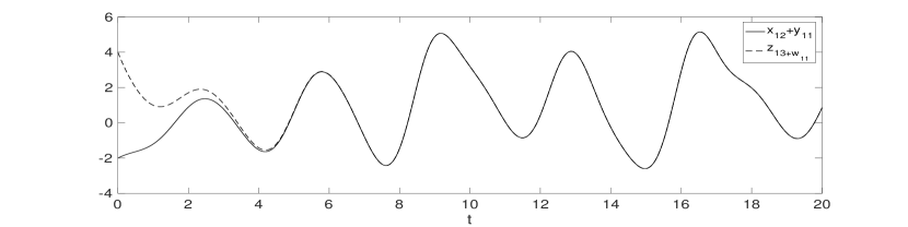
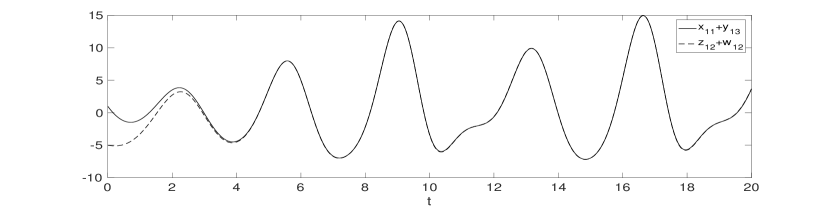
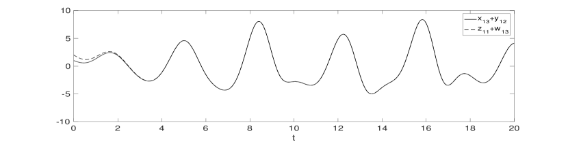
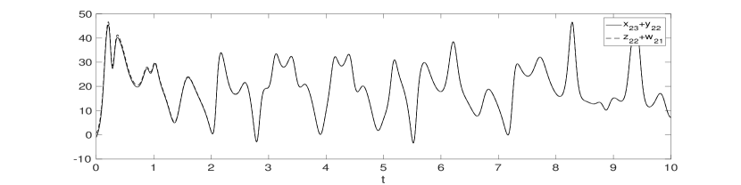
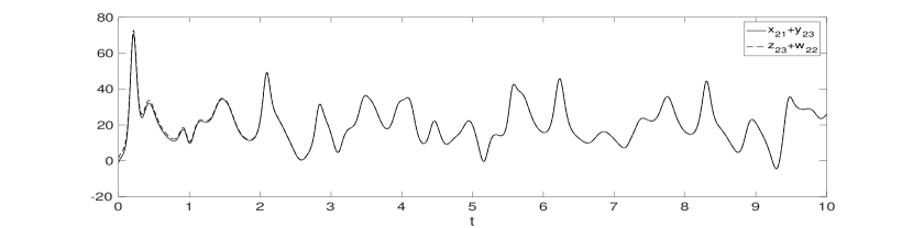
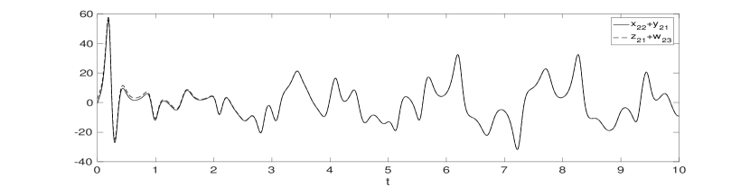
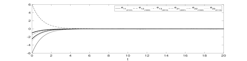
These controllers (31) and (32) are designed in accordance with Theorem 1 in order to realise the desired synchronization. In the numerical simulations process the initial conditions of the drive and response systems are chosen as (x11,x12,x13)=(2,3,1)subscript𝑥11subscript𝑥12subscript𝑥13231(x_{11},x_{12},x_{13})=(2,-3,1), (x21,x22,x23)=(2.5,1,3)subscript𝑥21subscript𝑥22subscript𝑥232.513(x_{21},x_{22},x_{23})=(-2.5,1,-3), (y11,y12,y13)=(1,0,1)subscript𝑦11subscript𝑦12subscript𝑦13101(y_{11},y_{12},y_{13})=(1,0,-1), (y21,y22,y23)=(1.5,2,1.5)subscript𝑦21subscript𝑦22subscript𝑦231.521.5(y_{21},y_{22},y_{23})=(-1.5,2,1.5), (z11,z12,z13)=(4,3.5,3)subscript𝑧11subscript𝑧12subscript𝑧1343.53(z_{11},z_{12},z_{13})=(4,-3.5,3), (z21,z22,z23)=(0.5,1.5,0)subscript𝑧21subscript𝑧22subscript𝑧230.51.50(z_{21},z_{22},z_{23})=(-0.5,1.5,0), (w11,w12,w13)=(1,1.5,2)subscript𝑤11subscript𝑤12subscript𝑤1311.52(w_{11},w_{12},w_{13})=(1,-1.5,-2), and (w21,w22,w23)=(1,1.5,3)subscript𝑤21subscript𝑤22subscript𝑤2311.53(w_{21},w_{22},w_{23})=(-1,1.5,3). Figures (1)(6)16(1)-(6) illustrates the time response of synchronized states and Figure (7)7(7) displays time response of synchronization errors. We can see that the desired dual combination combination multi switching synchronization is achieved with the controllers we designed.

Refer to caption
Figure 1: Response for states x12+y11subscript𝑥12subscript𝑦11x_{12}+y_{11} and z13+w11subscript𝑧13subscript𝑤11z_{13}+w_{11} for drive systems (23), (25) and response systems (27), (29).
Refer to caption
Figure 2: Response for states x11+y13subscript𝑥11subscript𝑦13x_{11}+y_{13} and z12+w12subscript𝑧12subscript𝑤12z_{12}+w_{12} for drive systems (23), (25) and response systems (27), (29).
Refer to caption
Figure 3: Response for states x13+y12subscript𝑥13subscript𝑦12x_{13}+y_{12} and z11+w13subscript𝑧11subscript𝑤13z_{11}+w_{13} for drive systems (23), (25) and response systems (27), (29).
Refer to caption
Figure 4: Response for states x23+y22subscript𝑥23subscript𝑦22x_{23}+y_{22} and z22+w21subscript𝑧22subscript𝑤21z_{22}+w_{21} for drive systems (24), (26) and response systems (28), (30).
Refer to caption
Figure 5: Response for states x21+y23subscript𝑥21subscript𝑦23x_{21}+y_{23} and z23+w22subscript𝑧23subscript𝑤22z_{23}+w_{22} for drive systems (24), (26) and response systems (28), (30).
Refer to caption
Figure 6: Response for states x22+y21subscript𝑥22subscript𝑦21x_{22}+y_{21} and z21+w23subscript𝑧21subscript𝑤23z_{21}+w_{23} for drive systems (24), (26) and response systems (28), (30).
Refer to caption
Figure 7: Time response of synchronization errors

5 Conclusions

The main purpose of this paper is to propose a novel scheme for synchronization involving eight chaotic systems. The proposed scheme dual combination combination multi switching synchronization achieves synchronization between four chaotic drive systems and four chaotic response systems in a multi switching manner. The main advantages of this scheme can be summarised as

i) The complexity of signal achieved by multiple combination enhances the security of transmitted signal, as the dynamic behaviour of resultant signal is so complex that it becomes very difficult, for the intruder, to separate the information signal from the transmitted signal. Thus in the context of secure communication applications, this scheme may provide improved performance and better resistance.

ii) The concept of multi switching in this scheme further strengthens the anti attack ability of the transmitted signals from drive systems because, for an intruder, determining the correct combination for error space vector is extremely difficult due to large number of possible synchronization directions.

iii) Several other synchronization schemes such as multi switching combination combination synchronization, dual combination multi switching synchronization, multi switching combination synchronization, dual multi switching projective synchronization, multi switching projective synchronization are obtained as special cases of dual combination combination multi switching synchronization scheme.

iv) The proposed scheme theoretically guarantees a good control performance.

v) The significant outcome may form the basis of several future studies.

Using Lyapunov stability theory, sufficient conditions are obtained for achieving dual combintaion combination multi switching synchronization. Numerical simulations has been demonstrated using four Genesio Tesi systems and four Lu systems to show the effectiveness and validity of the method. Using fractional order drive and response systems, or utilising the scheme to implement in secure communication applications, and designing the controllers in the presence of uncertain factors and disturbances in the system are some interesting directions for future work.

Acknowledgements

The work of the third author is supported by the Senior Research Fellowship of Council of Scientific and Industrial Research, India(Grant no. 09/045(1319)/2014-EMR-I).

References

References

  • [1] L. M. Pecora, T. L. Carroll, Synchronization in chaotic systems, Physical review letters 64 (8) (1990) 821–824.
  • [2] G. Chen, X. Dong, Methodologies, Perspectives and Applications, World Scientific, 1998.
  • [3] M. Chen, D. Zhou, Y. Shang, A new observer-based synchronization scheme for private communication, Chaos, Solitons & Fractals 24 (4) (2005) 1025–1030.
  • [4] X. J. Wu, J. Li, R. K. Upadhyay, Chaos control and synchronization of a three-species food chain model via holling functional response, International Journal of Computer Mathematics 87 (1) (2010) 199–214.
  • [5] M. Ma, J. Zhou, J. Cai, Practical synchronization of nonautonomous systems with uncertain parameter mismatch via a single state feedback control, International Journal of Modern Physics C 23 (11) (2012) 1250073.
  • [6] C. Yao, Q. Zhao, J. Yu, Complete synchronization induced by disorder in coupled chaotic lattices, Physics Letters A 377 (5) (2013) 370–377.
  • [7] H. L. Li, Z. Wang, Y. L. Jiang, L. Zhang, Z. Teng, Anti-synchronization and intermittent anti-synchronization of two identical delay hyperchaotic chua systems via linear control, Asian Journal of Control 19 (1) (2017) 202–214.
  • [8] S. Agrawal, S. Das, Function projective synchronization between four dimensional chaotic systems with uncertain parameters using modified adaptive control method, Journal of process control 24 (5) (2014) 517–530.
  • [9] I. Ahmad, A. B. Saaban, A. B. Ibrahim, M. Shahzad, M. M. Al Sawalha, Reduced-order synchronization of time-delay chaotic systems with known and unknown parameters, Optik-International Journal for Light and Electron Optics 127 (13) (2016) 5506–5514.
  • [10] M. Srivastava, S. Ansari, S. Agrawal, S. Das, A. Leung, Anti-synchronization between identical and non-identical fractional-order chaotic systems using active control method, Nonlinear Dynamics 76 (2) (2014) 905–914.
  • [11] S. Bowong, P. V. McClintock, Adaptive synchronization between chaotic dynamical systems of different order, Physics Letters A 358 (2) (2006) 134–141.
  • [12] S. Y. Li, C. H. Yang, C. T. Lin, L.-W. Ko, T. T. Chiu, Adaptive synchronization of chaotic systems with unknown parameters via new backstepping strategy, Nonlinear Dynamics 70 (3) (2012) 2129–2143.
  • [13] C. Li, K. Su, L. Wu, Adaptive sliding mode control for synchronization of a fractional-order chaotic system, Journal of Computational and Nonlinear Dynamics 8 (3) (2013) 031005.
  • [14] Y. Liu, P. Davis, Dual synchronization of chaos, Physical Review E 61 (3) (2000) R2176.
  • [15] A. A. Othman, M. S. M. Noorani, M. M. Al-Sawalha, Adaptive dual synchronization of chaotic and hyperchaotic systems with fully uncertain parameters, Optik-International Journal for Light and Electron Optics 127 (19) (2016) 7852–7864.
  • [16] A. A. Othman, M. Noorani, M. M. Al-sawalha, Adaptive dual anti-synchronization of chaotic systems with fully uncertain parameters, Optik-International Journal for Light and Electron Optics 127 (22) (2016) 10478–10489.
  • [17] V. K. Yadav, N. Srikanth, S. Das, Dual function projective synchronization of fractional order complex chaotic systems, Optik-International Journal for Light and Electron Optics 127 (22) (2016) 10527–10538.
  • [18] J. Sun, S. Jiang, G. Cui, Y. Wang, Dual combination synchronization of six chaotic systems, Journal of Computational and Nonlinear Dynamics 11 (3) (2016) 034501.
  • [19] A. K. Singh, V. K. Yadav, S. Das, Dual combination synchronization of the fractional order complex chaotic systems, Journal of Computational and Nonlinear Dynamics 12 (1) (2017) 011017.
  • [20] L. Runzi, W. Yinglan, D. Shucheng, Combination synchronization of three classic chaotic systems using active backstepping design, Chaos: An Interdisciplinary Journal of Nonlinear Science 21 (4) (2011) 043114.
  • [21] Z. Wu, X. Fu, Combination synchronization of three different order nonlinear systems using active backstepping design, Nonlinear Dynamics 73 (3) (2013) 1863–1872.
  • [22] J. Sun, Y. Shen, G. Zhang, C. Xu, G. Cui, Combination–combination synchronization among four identical or different chaotic systems, Nonlinear Dynamics 73 (3) (2013) 1211–1222.
  • [23] J. Sun, Y. Wang, G. Cui, Y. Shen, Dynamical properties and combination–combination complex synchronization of four novel chaotic complex systems, Optik-International Journal for Light and Electron Optics 127 (4) (2016) 1572–1580.
  • [24] J. Sun, Y. Shen, Q. Yin, C. Xu, Compound synchronization of four memristor chaotic oscillator systems and secure communication, Chaos: An Interdisciplinary Journal of Nonlinear Science 23 (1) (2013) 013140.
  • [25] C. Yang, H. Cai, P. Zhou, Compound generalized function projective synchronization for fractional-order chaotic systems, Discrete Dynamics in Nature and Society 2016.
  • [26] B. Zhang, F. Deng, Double-compound synchronization of six memristor-based lorenz systems, Nonlinear Dynamics 77 (4) (2014) 1519–1530.
  • [27] J. Sun, Y. Wang, Y. Wang, G. Cui, Y. Shen, Compound-combination synchronization of five chaotic systems via nonlinear control, Optik-International Journal for Light and Electron Optics 127 (8) (2016) 4136–4143.
  • [28] J. Sun, Y. Shen, Compound–combination anti-synchronization of five simplest memristor chaotic systems, Optik-International Journal for Light and Electron Optics 127 (20) (2016) 9192–9200.
  • [29] A. Ucar, K. E. Lonngren, E.-W. Bai, Multi-switching synchronization of chaotic systems with active controllers, Chaos, Solitons & Fractals 38 (1) (2008) 254–262.
  • [30] A. Radwan, K. Moaddy, K. N. Salama, S. Momani, I. Hashim, Control and switching synchronization of fractional order chaotic systems using active control technique, Journal of advanced research 5 (1) (2014) 125–132.
  • [31] X. Zhou, L. Xiong, X. Cai, Adaptive switched generalized function projective synchronization between two hyperchaotic systems with unknown parameters, Entropy 16 (1) (2013) 377–388.
  • [32] S. Zheng, Multi-switching combination synchronization of three different chaotic systems via nonlinear control, Optik-International Journal for Light and Electron Optics 127 (21) (2016) 10247–10258.
  • [33] U. E. Vincent, A. Saseyi, P. V. McClintock, Multi-switching combination synchronization of chaotic systems, Nonlinear Dynamics 80 (1-2) (2015) 845–854.