Spectral performance of SKA Log-periodic Antennas I: Mitigating spectral artefacts in SKA1-LOW 21-cm cosmology experiments
Abstract
This paper is the first in a series of papers describing the impact of antenna instrumental artefacts on the 21-cm cosmology experiments to be carried out by the low frequency instrument (SKA1-LOW) of the Square Kilometre Array telescope (SKA), i.e., the Cosmic Dawn (CD) and the Epoch of Reionization (EoR). The smoothness of the passband response of the current log-periodic antenna being developed for the SKA1-LOW is analyzed using numerical electromagnetic simulations. The amplitude variations over the frequency range are characterized using low-order polynomials defined locally, in order to study the impact of the passband smoothness in the instrument calibration and CD/EoR Science. A solution is offered to correct a fast ripple found at 60 MHz during a test campaign at the SKA site at the Murchison Radio-astronomy Observatory, Western Australia in September 2015 with a minor impact on the telescope’s performance and design. A comparison with the Hydrogen Epoch of Reionization Array antenna is also shown demonstrating the potential use of the SKA1-LOW antenna for the Delay Spectrum technique to detect the EoR.
keywords:
instrumentation: detectors – dark ages, reionization, first stars1 Introduction

The Square Kilometre Array (SKA)111http://www.skatelescope.org is a next generation radio telescope, with unprecedented sensitivity and survey speed. The SKA will explore the southern hemisphere skies faster and deeper than any other radio telescope has ever done. Spread across two continents (Southern Africa and Australia + New Zealand), it will cover a frequency range from 50 MHz up to 14 GHz and will tackle fundamental problems in modern Astrophysics including the study of the Cosmic Dawn (CD) and the Epoch-of-Reionization (EoR) as described in Koopmans et al. (2015). Phase I of the SKA will have a lower frequency instrument (SKA1-LOW: 50-350 MHz) that will be used for the study of the early epochs of the Universe by looking at the redshifted signal from the 21-cm Hydrogen emission line. This instrument will be located in Western Australia. It will be a 512 station interferometer with baselines up to 60 km and more than 130,000 antenna elements (Turner, 2015). Each station has been designed as a pseudo-random array of wide band antennas in order to minimize the effects of mutual coupling as shown by Gonzalez-Ovejero et al. (2011) and de Lera Acedo et al. (2011) and the effects of side-lobes (Razavi-Ghods et al., 2012; El-makadema et al., 2014). Each station is 35 m in diameter in order to meet the desired beam-width (Mellema et al., 2013; Koopmans et al., 2015).
The SKA1-LOW antenna is proposed to be a log-periodic dipole array, SKALA (SKA Log-periodic Antenna). Version 1 of SKALA, SKALA-1 was described in de Lera Acedo et al. (2015b). SKALA-1 maximizes the telescope’s sensitivity over the field of view across the 7:1 frequency band due to its moderate to high directivity and flat impedance, in contrast to dipole antennas that have low directivity values and only show relatively flat impedance over a narrow frequency band (typically 2:1 or 3:1 at most). Subsequently, a mechanical upgrade of SKALA-1 was designed and built, SKALA-2, in order to improve the design for mass manufacturing with negligible impact on the electromagnetic performance of the antenna. This upgraded design was presented in de Lera Acedo et al. (2015a). A computer model of the SKALA-2 antenna is shown in Figure 1. This paper describes the modifications to the length of the SKALA-2 antenna arms and component values of capacitors and inductors in the input matching network of the Low-Noise Amplifier (LNA) in order to improve the spectral smoothness of the antenna system. The result of this improvement is SKALA-3.
Both the CD and EoR observations require a smooth response of the instrument across frequency to enable the detection of the faint signals buried in much brighter foreground signals and not to introduce instrumental spectral structure on scales of relevance for the neutral hydrogen signal (Trott & Wayth, 2016; Parsons et al., 2012; DeBoer et al., 2017).
This paper describes the analysis of the proposed SKA1-LOW antenna, SKALA-3, using a local low-order polynomial fitting in order to assess its performance against realistic CD/EoR science requirements. In Section 2 the requirements derived in Trott & Wayth (2016) are summarized. Section 3 describes the current antenna topology and performance. Section 4 focuses on the description of the analysis and the results from numerical simulations. Section 5 presents the improved bandpass smoothness to meet the science requirements of the proposed SKA1-LOW antenna. Section 6 shows a comparison with the Hydrogen Epoch of Reionization Array (HERA222http://reionization.org) antenna against requirements derived for the Delay Spectrum technique for EoR observations. Finally, Section 7 draws some conclusions.
2 Spectral calibration requirements
In Trott & Wayth (2016) a formal procedure for the derivation of spectral requirements for radio interferometers dedicated to 21-cm cosmology experiments is presented. Here, we use the requirements derived in that paper to assess the design of the SKALA-2 and SKALA-3 antennas. In a companion paper (Trott et al., 2017, Paper II), we use realistic simulations to test the calibration performance of these antennas, and a comparison dipole (Tingay et al., 2013; Wayth et al., 2017, the Murchison Widefield Array - Engineering Development Array).
| Frequency (MHz) | |
|---|---|
| 50 | 0.025 |
| 100 | 0.01 |
| 150 | 0.005 |
| 200 | 0.008 |
One of the spectral requirements affects the EoR Power spectrum pipeline and is related to the level of the amplitude residuals after fitting a low-order polynomial locally to the station’s complex-valued voltage gain passband. The power derived from fitting a low-order (n = 2, 3, 4) polynomial over three contiguous coarse channels (2.25 MHz) yields structured power in the power spectrum space. This power is less than the thermal noise, but has the potential to cause low-level bias in the derived science results due to its shape. Table 1 lists the relative fractional bandpass errors tolerable in a fourth-order polynomial residual on voltage gain amplitudes at 4 different frequencies (In Trott & Wayth, 2016, requirements were also derived for second and fourth other polynomial fittings). Strictly speaking this should be applied to the station beam passband. Our current analysis has been done at the antenna level, which will dominate the passband response of the instrument. Further analysis is needed to include station beam effects such as mutual coupling and other antenna effects such as polarization and the instrument’s response across the whole field of view (including spectral variations in the far field pattern of the antenna).
Furthermore, in Trott & Wayth (2016) requirements are derived for the necessary smoothness in the phase passband of the station’s voltage gain. Phase residuals affect the imaging (tomography) experiment substantially. The so-called “phase noise" decorrelates the visibilities and adds an effective noise to the images that swamps the signal. So, in Trott & Wayth (2016) the maximum change in phase across any fine channel (within the 100 - 200 MHz band) that would lead to swamping of the expected EoR signal is computed. In the worst case where the phase residual on each channel is fixed over the full experiment, there cannot be more than a 0.04 degree change of phase over any fine channel (4.58 kHz). An optimistic case where the phase residual is uncorrelated in time between calibration cycles, yielding an increase in dynamic range and weaker constraints, raises that limit to 0.2 degrees.
3 SKALA antenna and LNA performance
The SKALA-1 and SKALA-2 antennas were designed to maximize the sensitivity of the SKA1-LOW instrument across at least a 7:1 frequency band by means of optimizing its effective area, minimizing its footprint and average distance between elements (to maximize brightness sensitivity for a fixed number of elements) and reducing receiver noise (dominated by the matching between the antenna and the first stage low-noise amplifier).
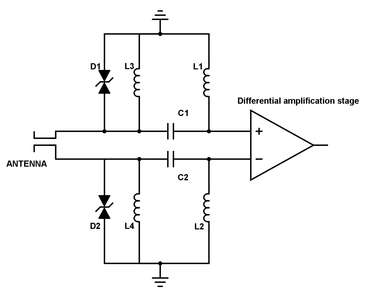
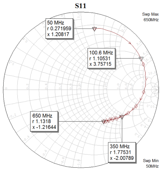
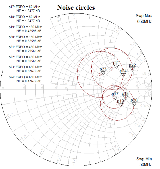
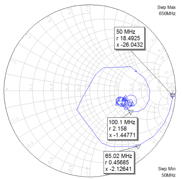
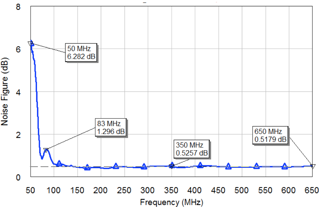
The antenna simulations were carried out using CST333Computer Simulation Technology AG, http://www.cst.com for the antenna and Microwave Office444http://www.awrcorp.com/products/ni-awr-design-environment/microwave-office for the LNA. The LNA design is based on a pseudo-differential configuration with a first differential amplification stage using Qorvo555http://www.qorvo.com transistors (TQP3M9039) and a second amplification stage after a wide band balun transformer using a Mini-Circuits666http://www.minicircuits.com transistor (PSA-5451+). Figure 2 shows the simplified schematic of the first amplification stage. Figure 3 shows the input LNA impedance (), the LNA optimum noise impedance at the center of the noise circles () and the antenna input impedance () across frequency. It is well known that the process of noise matching and power matching calls for a trade-off between achieving a low noise figure and a smooth passband with maximum power transfer (Pozar, 2011). Figure 3 shows that the optimum noise impedance of the LNA, which we need to match our antenna to for minimum noise figure, and the input impedance of the LNA, which we need to match our antenna impedance to for maximum power transfer, are not in the same place in the Smith chart. SKALA-1 was originally designed to cover the band of 70-450 MHz and it was later optimized to work down to 50 MHz with the focus on maximum sensitivity and therefore minimum receiver noise, hence it is matched to the optimum noise impedance of the LNA. The noise figure of the LNA connected to SKALA-2 is shown in Figure 4 and the passband is shown in red in Figure 8 and Figure 9. The passband here is the voltage gain of the LNA, , when connected to the antenna impedance (not a fixed reference impedance), thus the performance is as it would be in a real scenario. The antenna was simulated standing on top of an infinite perfect electric conductor ground plane. A low receiver noise was achieved down to 100 MHz where the sky noise starts to severely dominate the system noise and we can relax the receiver noise requirements. However, the passband response of the LNA when connected to the antenna impedance, exhibits several sharp features, especially one around 60 MHz.
It is important to notice that according to the definition of sensitivity used here and described by equation 1 (effective area over system temperature or signal over noise) the the passband smoothness will not be visible in that metric. The reason for this is that the ratio of effective area over system noise temperature is constant independent of where the ratio is taken in the receiving chain. In equation 1 we refer this ratio to the input of the LNA and therefore both effective aperture and system noise temperature (all of the noise terms) will be equally weighted by the gain of the LNA, as if we try to calculate this ratio at the output of the LNA. This is correct as long as we have taken into account the noise contribution from the rest of the receiving chain (after the LNA) weighted by the gain of the previous stages (in order to refer it to the input of the LNA). Since the gain of the LNA is high and the noise figure of the following stages is small, this contribution is negligible. Consequently, the effect of the passband gain of the LNA will not be visible in the sensitivity values. In equation 1, is the wavelength, is the antenna’s directive gain, is the radiation efficiency, is the antenna temperature (including the sky temperature), is the ambient temperature (295 K) and is the receiver noise temperature. For more details, see de Lera Acedo et al. (2015b).
| (1) |


4 Spectral analysis using local low-order polynomial fitting
In this section we analyze the response of the SKALA-2 antenna measuring it against the requirements presented in Trott & Wayth (2016). As mentioned before we simulate the passband of one antenna alone, because it dominates the passband response across frequency of the station beam. Furthermore, we focus on the passband response of the LNA when connected to the antenna omitting the effect of the antenna far field pattern since this is much more smooth than that of the LNA and will not affect these results. The frequency band (50 - 350 MHz) is subdivided into coarse channels 750 kHz wide, each of which is subdivided into fine channels 4.6 kHz wide. This means 163 fine channels per every coarse channel. We fit an n-order polynomial (by default in this paper the order is 3) to all fine frequency channels in a least-squares sense across m coarse channels (by default in this paper m is 3 as well) to both the real and imaginary parts of the passband. The fitted complex passband (), where the fit has been performed separately to its real part () and its imaginary part (), follows the definition of equation 2 ( is the frequency and is the central frequency for each coarse channel). The polynomial fit is only used to model the fine channels corresponding to the middle coarse channel of the m channels used to generate the fit. We can then subtract the model of the amplitude response from the amplitude of the passband data () and normalize this difference by again to get the residuals () as in equation 3. This process is repeated for all the fine channels in the frequency bandwidth by moving the central coarse channel by one (and consequently fitting the next set of fine channels) to obtain the wide-band performance of the antenna. While the default bandwidth used for the polynomial fitting in this paper is 2.25 MHz (3 coarse channels), in Barry et al. (2016) it is recommended that smoothness is also achieved in larger bandwidths in order to prevent contamination of the relevant modes for the EoR detection. We have therefore extend our analysis here to 9 coarse channels (6.75 MHz). The choice of the order of the polynomial is also important, since high orders could constrain the fit in excess and remove not only the instrument’s passband but also the cosmological signal. Furthermore, high-order polynomial fittings would result as well in high-order residuals at potentially similar spectral scales to that of the cosmological signal. While he have stayed at a relatively low order here (3), in Trott et al. (2017) the effects of using higher order polynomials are also discussed.
| (2) |
| (3) |
The phase gradient per fine channel, , is calculated using equation 4.
| (4) |
Figure 5 shows how the required residuals are not met by SKALA-2 at the frequency where the passband has peaked behaviour in amplitude and a fast slope in the phase due to the mismatch between the antenna and the LNA. The phase gradient requirement seems to be more under control than the amplitude requirement, especially in the band 100 to 200 MHz, although it is again higher at lower frequencies as indicated in Figure 6.
5 Improvement of the bandpass smoothness
5.1 Antenna and LNA modifications
The spectral response of the antenna is dominated by the mismatch between the antenna and the first stage low-noise amplifier. In order to improve the power match between the antenna and the low-noise amplifier, we have explored modifications of both systems specifically where we were not meeting the passband requirements (50-100 MHz).
In SKALA-3, we have modified the input network of the LNA (see Figure 2) using the original input matching components but with a lower value of the DC blocking capacitors and bias inductors (150 nH ESD shunt inductors remain the same (L3 and L4), 24 pF DC blocking capacitors (C1 and C2), 270 nH bias inductors (L1 and L2)). The trade-off is a higher noise figure, peaking at almost 8.6 dB at 57 MHz. This is a side effect of using a smaller-value inductor in the bias network after we added a resistor for stability. We don’t want to change that resistor, and making that inductor larger immediately sharpens the peak in the gain response. The series capacitor could be reduced in value to smooth the ripple even further, but the peaking in the noise figure starts to increase rapidly (18 pF gives in excess of 10 dB noise figure).
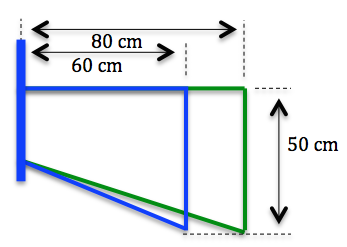
In order to bring the antenna impedance closer to the LNA input impedance, facilitating the match, we have enlarged the bottom dipole of the antenna (active at the lower end of the band). The design is shown in Figure 7. This increases the footprint of the antenna to 1.6 x 1.6 m instead of 1.2 x 1.2 m. While it is possible from an electromagnetic point of view to interleave antenna footprints in a SKA station it may not be appropriate for maintenance of the antennas. We are exploring a larger station size (40 m) to support this new design while minimizing the impact in the station performance.


5.2 Improved antenna response and impact on SKA1-LOW sensitivity
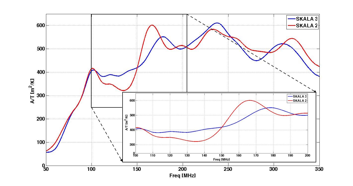
With the changes presented above we recalculated the performance of the new version of the SKALA antenna (SKALA-3). Figures 8 and 9 show the new LNA amplitude and phase passbands when connected to the antenna impedance. Figure 5 shows the amplitude residuals for SKALA-3, now within the requirements, for a third order polynomial fitted across 3 coarse channels. In Table 2 we also list the residuals for wider bandwidths and a polynomial of order 3 fitting the data. We simulated for 5 coarse channels (3.75 MHz), 7 coarse channels (5.25 MHz) and 9 coarse channels (6.75 MHz). We observe an increase in the residuals when we try to fit a wider frequency bandwidth with a polynomial of order 3 but always staying below the requirement limit. Figure 6 shows how the phase gradient has improved at all frequencies therefore still meeting the requirements in the EoR band. Finally, Figure 10 show the effect on the SKA1-LOW sensitivity when using the new antenna, SKALA-3. The sensitivity has been calculated using equation 1. This is also flatter across frequency. The antenna’s directive gain (directivity) is one of the main contributors to the effective aperture and therefore to the sensitivity of the antenna as described in de Lera Acedo et al. (2015b). The change in the length of the bottom dipole of SKALA in order to improve the low frequency impedance match with the LNA has caused, as expected, a smoother transition between the bottom dipole and the second dipole. This has produced a flatter directivity of the antenna across frequency and therefore a flatter sensitivity pattern.
| Frequency (MHz) | (m = 5) | (m = 7) | (m = 9) |
|---|---|---|---|
| 50 | 0.00073 | 0.00612 | 0.01327 |
| 100 | 0.00009 | 0.00017 | 0.00074 |
| 150 | 0.00090 | 0.00100 | 0.00110 |
| 200 | 0.00003 | 0.00003 | 0.00004 |
6 The Delay Spectrum metric
A well-studied way to look at antenna spectral requirements is from the perspective of foreground avoidance in power spectrum space. In the avoidance scheme, smooth–spectrum foregrounds should, in the ideal case, occupy a wedge–shaped region of the two–dimensional power spectrum space (where the wave number can be decomposed into and that are the transverse and line-of-sight wave numbers respectively) whereas the remaining area – the so–called EoR window – is dominated by the 21 cm emission (Datta et al., 2010; Morales et al., 2012; Thyagarajan et al., 2013; Liu et al., 2014a, b; Trott et al., 2012; Vedantham et al., 2012). Sources have most of their emission at low values although, due to the inherent chromatic interferometric response, this area increases with baseline length to resemble a characteristic wedge–like shape (Parsons et al., 2012; Liu et al., 2014a, b; Thyagarajan et al., 2015; Trott et al., 2012; Vedantham et al., 2012). In the most optimistic scenario, the EoR power spectrum can be directly measured in the EoR window, whose boundaries are set by the so called horizon limit, i.e. the maximum delay that an astrophysical signal can experience, given by the separation of the two receiving elements. In practice, the boundaries of the EoR window can be narrowed by a number of mechanisms that spread power from the foreground dominated region into the EoR window, in particular calibration errors (Barry et al., 2016; Patil et al., 2016), leakage of foreground polarization (Bernardi et al., 2010; Jelić et al., 2010; Moore et al., 2013; Asad et al., 2015, 2016) and intrinsic chromaticity of the instrumental response. Recent attention has indeed been given to simulate and characterize the element response, particularly for the Hydrogen Epoch of Reionization Array (DeBoer et al., 2017), realizing that it may be one of the critical items responsible for spilling power from the wedge into the EoR window.
The HERA design leverages a highly-redundant array configuration that accumulates its maximum sensitivity on a limited number of modes, building on the results of the Precision Array to Probe the Epoch of Reionization (Parsons et al., 2014; Jacobs et al., 2015; Ali et al., 2015, PAPER). Like PAPER, HERA plans to employ a foreground avoidance scheme on a per-baseline base, through the delay transform. In equation 5, is the delay () transform (inverse Fourier transform) of the measured frequency visibility for a fixed baseline (equation 6), that includes the sky brightness, and the antenna’s directional power pattern, . is the speed of light, is the baseline vector and is the direction on the sky (unit vector). The sky power spectrum can then be approximated by equation 7, where is the effective bandwidth, is the integrated beam response, is the Boltzmann’s constant and and are cosmological parameters relating angular size and spectral frequency to cosmic volumes respectively. For more details, see Parsons et al. (2012).
| (5) |
| (6) |
| (7) |
The delay transform has therefore been used as a metric to characterize the response of the HERA dish (Ewall-Wice et al., 2016; Neben et al., 2016; Thyagarajan et al., 2016; Fagnoni & de Lera Acedo, 2016).
Given its very compact configuration, HERA achieves its highest sensitivity on a 14.6 m baseline and, in order to suppress foregrounds to below the EoR level at the corresponding -mode, requires high suppression at high delays (DeBoer et al., 2017). Ewall-Wice et al. (2016) and Thyagarajan et al. (2016) show that the current dish+feed response suppresses foregrounds below the EoR signal at ns; access to smaller modes, however, can still be achieved using an optimal weighting scheme (Liu & Tegmark, 2011; Ali et al., 2015). Although the SKA will adopt a different array configuration, motivated by imaging requirements that need a more random coverage, the delay spectrum metric can be used to characterize its antenna response too.
Ewall-Wice et al. (2016) describes how to perform a simulated analysis of the antenna system to measure its capabilities for EoR detection using the Delay Spectrum technique. We have followed a similar approach here but extended to include the effects of the matching to the LNA. The design goal is to reduce the response of the antenna in the delay spectrum for large values of delay (corresponding to large values of ) to avoid contamination of the EoR window. The core EoR detection will be done using modes greater than 0.1 h/Mpc and therefore we should make sure that any power introduced by reflections in our instrument is below the EoR HI signal. A plane wave incoming from zenith is used to excite the HERA antenna. The same process is used to excite the SKALA-3 antenna. Circuit models of the LNAs for both HERA and SKA have been connected to the antennas in the simulation to represent the effects of the mismatch between the antenna and the LNA in their response. Separate time domain full electromagnetic simulations (using the CST program) were then performed to obtain the output signal of the pair antenna+LNA for both systems. The transfer function of the antenna is then calculated by dividing in Fourier space the output voltage signal by the input signal (the plane wave) used as excitation. Finally the calculated transfer function is transformed to the delay domain by applying an inverse Fourier transform. Figures 11 and 12 show this transfer function for both antennas in two frequency bands relevant to the CD/EoR science, 100-200 MHz and the extended band 50-250 MHz. These plots are normalized to the amplitude of the first incidence of the plane wave in the HERA feed after an initial reflection in the dish and to the direct incidence in the SKALA-3 antenna respectively. These incidence times are used as = 0 ns.


In Figure 11 we can see that the SKALA-3 performance is comparable to that of the HERA antenna including feed and dish for a large portion of significant delays for the band 100-200 MHz. In Figure 12 we can see how the response of SKALA-3 also seems to be competitive in the extended band (50-250 MHz). In these simulations the effects of the multiple reflections on the HERA dish are included. This result is likely to change when the effects of mutual coupling are included for both systems. In the case of SKA1-LOW the antennas in a station will be arranged in a pseudo-random configuration and they will be placed at about 2 meters from each other on average. However for HERA the configuration is triangular-regular and the distance between antennas is 14.6 m. While the level of the coupling will be therefore higher for SKA, it is also worth noticing that the effects of mutual coupling tend to average out in random arrays (de Lera Acedo et al., 2011). The actual impact of coupling could therefore be assumed to be non dominant, but further work will explore these effects in more detail. The HERA results shown here are consistent with those shown in Ewall-Wice et al. (2016) although the results in this paper include the effects the mismatch with the actual LNA.
It is also worth noting that HERA only uses relatively short baselines to prevent the contamination of the EoR window.
7 Conclusions and future work
In this paper we have presented two different analyses of the passband response of realistic antennas for 21-cm cosmology experiments. One is based on fitting a local low-order polynomial to the passband in order to model and calibrate it. The second is based on building an antenna design free of spectral structure at the relevant scales for the detection of the EoR following the Delay Spectrum technique proposed for HERA. The analyses have been done using the improved log-periodic antenna proposed for SKA1-LOW (SKALA-3).
Using electromagnetic and RF computer simulations of the antennas and LNAs, we have shown that with minor modifications on the antenna and LNA design it is possible to improve the impedance matching that dominates the spectral performance of the system meeting the passband smoothness requirements established in Trott & Wayth (2016). Furthermore, these modifications result in a design able to use the Delay Spectrum technique provided that other considerations are also taken into account (e.g. the effects of mutual coupling and side-lobes have not been taken into account in this analysis). The main parameters of the antenna such as sensitivity are only slightly affected by these changes, however, the overall response has been flattened at reduced spectral scales over the frequency range.
These analyses are now going to be validated using measurements on a prototype. Furthermore, we will shortly add to the study an analysis of the effects of mutual coupling and other sources of spectral features in the instrument’s passband (e.g. side-lobes as in Thyagarajan et al. (2016)). In particular, beam-formed arrays of antennas are studied in paper II in this series (Trott et al., 2017). In Trott et al. (2017) realistic interferometric and sky simulations (including frequency-dependent primary beam shapes and array configuration) are used to study the calibration performance of the antennas. It applies a weighted least squares polynomial estimator to assess the precision with which each antenna type can calibrate the instrument, and compares to the tolerances described in Trott & Wayth (2016). Further work will also be done to assess the impact of the spectral smoothness of realistic beam-forming technologies and techniques.
Acknowledgements
The authors thank Paul Alexander and the SKA Office for useful discussions. The authors would like to acknowledge their SKA Aperture Array Design Consortium colleagues for their help and discussions on the topic. This research was supported by the Science & Technology Facilities Council (UK) grant: SKA, ST/M001393/1 and the University of Cambridge, UK. This research was also supported under the Australian Research Council’s Discovery Early Career Researcher funding scheme (project number DE140100316), and the Centre for All-sky Astrophysics (an Australian Research Council Centre of Excellence funded by grant CE110001020). This work was supported by resources provided by the Pawsey Supercomputing Centre with funding from the Australian Government and the Government of Western Australia. We acknowledge the iVEC Petabyte Data Store, the Initiative in Innovative Computing and the CUDA Center for Excellence sponsored by NVIDIA at Harvard University, and the International Centre for Radio Astronomy Research (ICRAR), a Joint Venture of Curtin University and The University of Western Australia, funded by the Western Australian State government. The authors also acknowledge support from the Royal Society and the Newton Fund under grant NA150184. This work is based on the research supported in part by the National Research Foundation of South Africa (Grant Number 103424).
References
- Ali et al. (2015) Ali Z. S., et al., 2015, ApJ, 809, 61
- Asad et al. (2015) Asad K. M. B., et al., 2015, MNRAS, 451, 3709
- Asad et al. (2016) Asad K. M. B., et al., 2016, MNRAS, 462, 4482
- Barry et al. (2016) Barry N., Hazelton B., Sullivan I., Morales M. F., Pober J. C., 2016, MNRAS, 461, 3135
- Bernardi et al. (2010) Bernardi G., et al., 2010, A&A, 522, A67
- Datta et al. (2010) Datta A., Bowman J. D., Carilli C. L., 2010, ApJ, 724, 526
- DeBoer et al. (2017) DeBoer D. R., et al., 2017, PASP, 129, 045001
- El-makadema et al. (2014) El-makadema A., Rashid L., K. Brown A., 2014, IEEE TAP, 62, 1673
- Ewall-Wice et al. (2016) Ewall-Wice A., et al., 2016, ApJ, 831, 196
- Fagnoni & de Lera Acedo (2016) Fagnoni N., de Lera Acedo E., 2016, preprint, (arXiv:1606.08701)
- Gonzalez-Ovejero et al. (2011) Gonzalez-Ovejero D., de Lera Acedo E., Razavi-Ghods N., Craeye C., Garcia Munoz L. E., 2011, in APS2011. pp 1762–1765, doi:10.1109/APS.2011.5996835
- Jacobs et al. (2015) Jacobs D. C., et al., 2015, ApJ, 801, 51
- Jelić et al. (2010) Jelić V., Zaroubi S., Labropoulos P., Bernardi G., de Bruyn A. G., Koopmans L. V. E., 2010, MNRAS, 409, 1647
- Koopmans et al. (2015) Koopmans L., et al., 2015, Advancing Astrophysics with the Square Kilometre Array (AASKA14), p. 1
- Liu & Tegmark (2011) Liu A., Tegmark M., 2011, Phys. Rev. D, 83, 103006
- Liu et al. (2014a) Liu A., Parsons A. R., Trott C. M., 2014a, Phys. Rev. D, 90, 023018
- Liu et al. (2014b) Liu A., Parsons A. R., Trott C. M., 2014b, Phys. Rev. D, 90, 023019
- Mellema et al. (2013) Mellema G., et al., 2013, Exp. Astron, 36, 235
- Moore et al. (2013) Moore D. F., Aguirre J. E., Parsons A. R., Jacobs D. C., Pober J. C., 2013, ApJ, 769, 154
- Morales et al. (2012) Morales M. F., Hazelton B., Sullivan I., Beardsley A., 2012, ApJ, 752, 137
- Neben et al. (2016) Neben A. R., et al., 2016, ApJ, 826, 199
- Parsons et al. (2012) Parsons A. R., Pober J. C., Aguirre J. E., Carilli C. L., Jacobs D. C., Moore D. F., 2012, The Astrophysical Journal, 756, 165
- Parsons et al. (2014) Parsons A. R., et al., 2014, ApJ, 788, 106
- Patil et al. (2016) Patil A. H., et al., 2016, MNRAS, 463, 4317
- Pozar (2011) Pozar D., 2011, Microwave Engineering, 4th Edition. Wiley, https://books.google.co.uk/books?id=JegbAAAAQBAJ
- Razavi-Ghods et al. (2012) Razavi-Ghods N., de Lera Acedo E., El-Makadema A., Alexander P., Brown A., 2012, Exp. Astron, 33, 141
- Thyagarajan et al. (2013) Thyagarajan N., et al., 2013, ApJ, 776, 6
- Thyagarajan et al. (2015) Thyagarajan N., et al., 2015, ApJ, 804, 14
- Thyagarajan et al. (2016) Thyagarajan N., Parsons A., DeBoer D., Bowman J., Ewall-Wice A., Neben A., Patra N., 2016, Astrophys. J., 825, 9
- Tingay et al. (2013) Tingay S. J., Goeke R., Bowman J. D., Emrich D., others 2013, PASA, 30, 7
- Trott & Wayth (2016) Trott C. M., Wayth R. B., 2016, Publ. Astron. Soc. Australia, 33, e019
- Trott et al. (2012) Trott C. M., Wayth R. B., Tingay S. J., 2012, ApJ, 757, 101
- Trott et al. (2017) Trott C. M., de Lera Acedo E., Wayth R. B., Fagnoni N., Sutinjo A. T., Wakley B., Punzalan C. I., 2017, MNRAS, submitted, Paper II
- Turner (2015) Turner W., 2015, SKA-TEL-SKO-0000008, SKA Phase 1 System Level 1 Requirements (Rev 6)
- Vedantham et al. (2012) Vedantham H., Udaya Shankar N., Subrahmanyan R., 2012, ApJ, 745, 176
- Wayth et al. (2017) Wayth R. B., et al., 2017, Publ. Astron. Soc. Australia, in prep.
- de Lera Acedo et al. (2011) de Lera Acedo E., Razavi-Ghods N., Ovejero D. G., Sarkis R., Craeye C., 2011, in ICEAA2011. pp 390–393, doi:10.1109/ICEAA.2011.6046372
- de Lera Acedo et al. (2015a) de Lera Acedo E., Drought N., Wakley B., Faulkner A., 2015a, in 2015 International Conference on Electromagnetics in Advanced Applications (ICEAA). pp 839–843, doi:10.1109/ICEAA.2015.7297231
- de Lera Acedo et al. (2015b) de Lera Acedo E., Razavi-Ghods N., Troop N., Drought N., Faulkner A. J., 2015b, Experimental Astronomy, 39, 567