Current Induced Dynamics of Multiple Skyrmions with Domain Wall Pair and Skyrmion-based Majority Gate Design
Abstract
As an intriguing ultra-small particle-like magnetic texture, skyrmion has attracted lots of research interests in next-generation ultra-dense and low power magnetic memory/logic designs. Previous studies have demonstrated a single skyrmion-domain wall pair collision in a specially designed magnetic racetrack junction. In this work, we investigate the dynamics of multiple skyrmions with domain wall pair in a magnetic racetrack. The numerical micromagnetic simulation results indicate that the domain wall pair could be pinned or depinned by the rectangular notch pinning site depending on both the number of skyrmions in the racetrack and the magnitude of driving current density. Such emergent dynamical property could be used to implement a threshold-tunable step function, in which the inputs are skyrmions and threshold could be tuned by the driving current density. The threshold-tunable step function is widely used in logic and neural network applications. We also present a three-input skyrmion-based majority logic gate design to demonstrate the potential application of such dynamic interaction of multiple skyrmions and domain wall pair.
Index Terms:
Multiple skyrmions, domain wall pair, threshold function, majority gate.I Introduction
Skyrmion is a particle-like spin texture which has been experimentally observed both in B20 type bulk material (MnSi [1], Fe1-xCoxSi [2, 3], FeGe [4, 5]) and ultra-thin ferromagnetic film (Ta/CoFeB/TaOx [6] and Pt/CoFeB/MgO [7]) favored by Dzyaloshinskii-Moriya Interaction (DMI). Owing to its topological stability, skyrmion has been widely investigated in recent years for racetrack memory [8], logic [9] [10], oscillator [11], transistor [12] and neuromorphic computing [13]. The dynamics between single domain wall pair (DWP) and single skyrmion has been studied in [10]. In this work, we investigate the dynamical interaction between multiple skyrmions and single domain wall pair in a magnetic racetrack. The conducted micromagnetic simulation reveals that the pinning and depinning of a DWP from a rectangular notch is determined by both the number of skyrmions (defined as threshold skyrmion number) and the magnitude of driving current density. Increasing the driving current density leads to larger skyrmion and DWP drifting velocity, but lowering the threshold skyrmion number. Such skyrmions and DWP interaction behavior can be used to design a threshold-tunable step function, in which the inputs are skyrmions and threshold could be tuned by the driving current density. In the end, we present a skyrmion-based majority logic gate design as an example to demonstrate a potential logic application.
II Skyrmions-Domain Wall Pair Dynamics
II-A Device structure and basic operations
 |
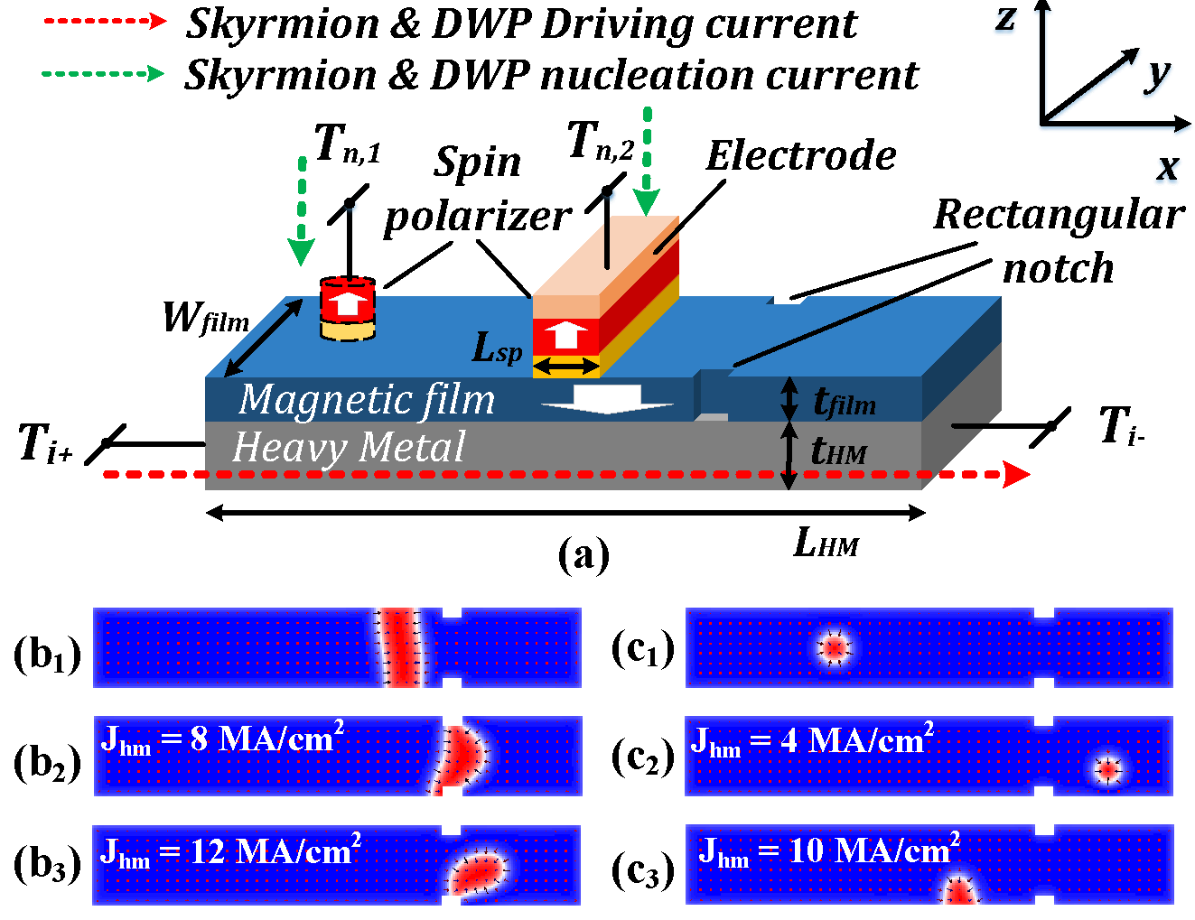
As the multilayer device structure shown in Fig. 1(a), the nanotrack constitutes of heavy metal substrate, ultra-thin ferromagnetic film, and spin polarizers which are mounted on the top for Domain Wall Pair (DWP) and skyrmions nucleation. By vertically injecting current pulse through the spin polarizers [10], DWP and skyrmion can be nucleated within the ferromagnetic film. For the generation of multiple skyrmions, a shift operation is necessary followed by the skyrmion nucleation, which is similar as skyrmion racetrack memory [14]. Current-driven skyrmion- and domain wall-motion haven been previously explored as an effective manipulation mechanism to relocate skyrmion and DWP in nanostructures [15]. Compared to directly injecting spin polarized current into magnetic film along x-axis, utilizing Spin Hall Effect (SHE) is a more efficient skyrmion and DWP manipulation method due to higher drifting velocity with identical driving current density [15]. When applying a lateral charge current through heavy metal (Ti+ and Ti- in Fig. 2), a pure spin current is generated along z-axis and exerts Slonczewski Spin-Transfer Torque on the spin textures. Such driving force can be described as [15]:
| (1) |
where is the spin Hall angle, is reduced Planck constant, is the skyrmion characteristic length, and is the spin polarized direction. The sign of is determined by the sign of topological charge , which is equivalent with the skyrmion number. When the magnetization of one isolated skyrmion core is pointing towards +z, whereas [6]. It is noteworthy that, all the discussions and mathematical descriptions in the work are based on Néel-type skyrmion and domain wall, owing to the interfacial DMI [16].
While the driving current is below the critical depinning current density of DWP (), as seen in Fig. 1(b2), the DWP moves along the nanotrack until trapped within the rectangular notch [17]. Otherwise, the DWP converts into a meron [18], then annihilates at the nanotrack border when the driving current is turned off. Conversely, as a result of repulsion force between skyrmion and nanotrack boundary, skyrmion has better variation tolerance to move through pinning notch and device edge roughness [15]. However, owing to the skyrmion Hall effect [6] [19], larger driving current density makes skyrmion collides with nanotrack boundary as depicted in Fig. 1(c3). Therefore, in this work, we restrict the current density () to be less than to assure the correct operation of skyrmions and DWP.
II-B Skyrmions dynamics with domain wall pair
The skyrmion motion driven by SHE can be modeled by the modified Thiele equation [15] [6] [8] [20] [21]:
| (2) |
where is the gyro-magnetic coupling vector (). is the velocity of skyrmion motion, which consists of two components and along x- and y-axis. is the dissipative tensor, and is Gilbert damping factor. is the potential from surrounding environment, such as nanotrack boundary, process impurities and other spin textures [20]. The four terms in equation. 2 describe Magnus force, dissipative force, Slonczewski in-plane torque and effective Force respectively. Due to the repulsion force of skyrmion-skyrmion, skyrmion-domain wall and skyrmion-edge, the dimension of skyrmion shrinks, which consequently leads to the degradation of skyrmion velocity and driving STT ().
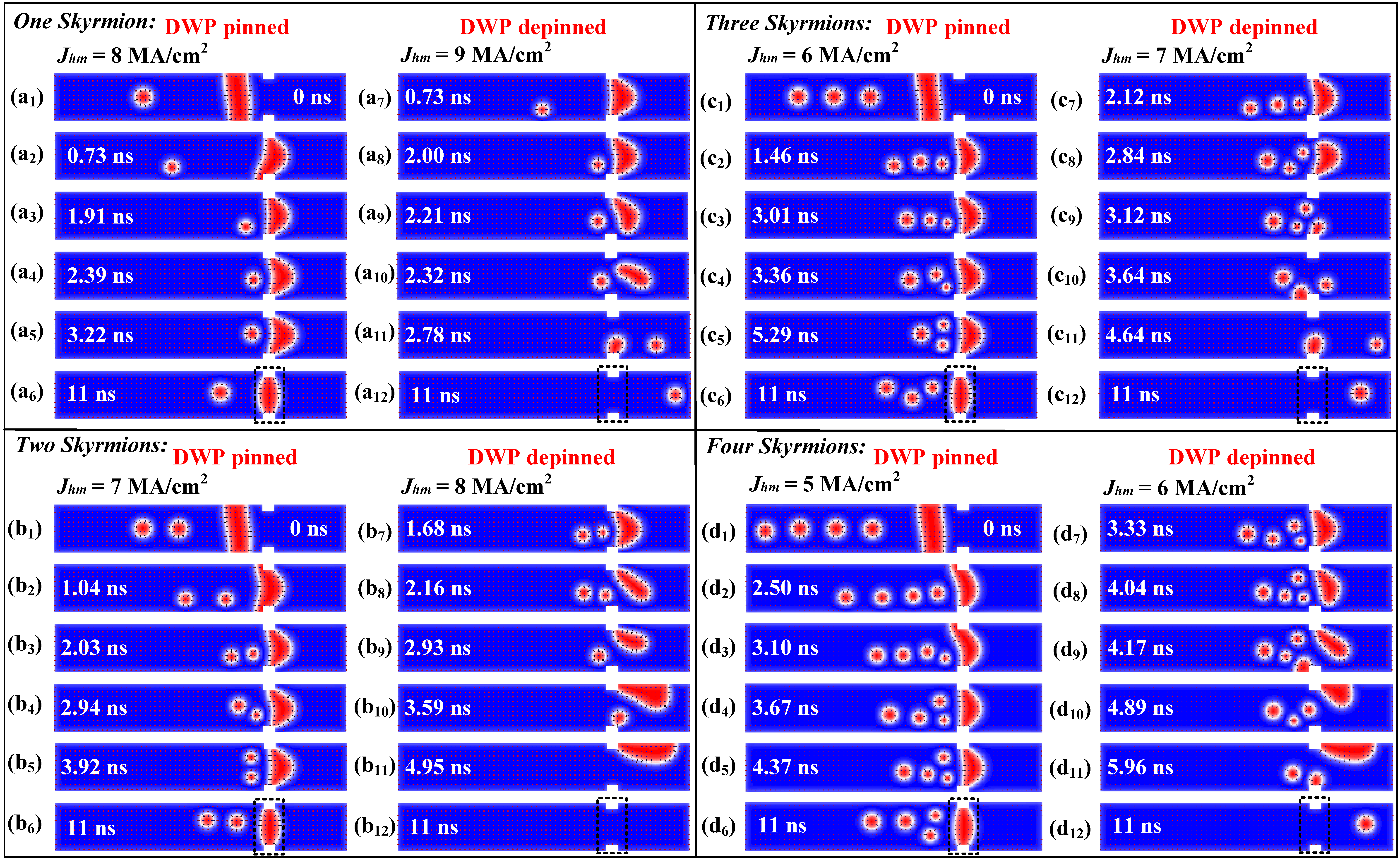
The micromagnetic simulation in Fig. 2 presents the current-driven dynamics between multiple skyrmions and DWP under 10-ns current pulse, with respect to different number of skyrmions and driving current densities (). In summary, the simulation results could be classified into two categories based on the pinning or depinning of DWP at the notch. As depicted in Fig. 2, for a specific number of skyrmions, domain wall pair can be either pinned or depinned at the rectangular notch by varying driving current density (). We take the DWP interacting with four skyrmions as an example. The skyrmions and DWP initially locate at the L.H.S of pinning site at 0ns. Fig. 2(d1-6) shows the skyrmions and DWP dynamics with . Since the DWP is closer to the notch, DWP will first get confined at the pinning site while the skyrmions still move along the nanotrack driven by until approaching the confined DWP. Owing to the mutual repulsion forces between skyrmions and DWP, which is not large enough to overcome the pinning effect, DWP will not be depinned. Then, when the driving current is turned off (after 10-ns), the distorted DWP is relaxed to normal shape. The case of same number (4) of skyrmions with larger current density () is shown in Fig. 2(d1,7-12), where the DWP gets depinned due to a large enough repulsion force from the accumulated skyrmions. After DWP gets depinned, it converts into a meron and the nanotrack channel is reopened for skyrmions to pass through the notch site. Meanwhile, part of skyrmions will collide with the boundary due to the uneven potentials from notch boundary and other magnetic textures. On the contrary, the skyrmions successfully passing the notch will be moved to the R.H.S, which could be destroyed either by a large current pulse or fork-like device geometry [22].
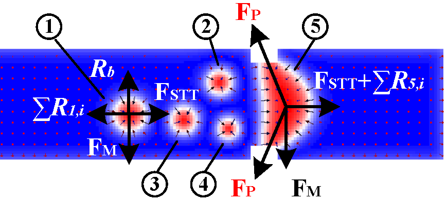
Beyond the general description of skyrmions and DWP interaction, we perfrom the force anaylsis to explain such intriguing dynamics. According to the force analysis shown in Fig. 3, four skyrmions (\raisebox{-0.9pt}{1}⃝ \raisebox{-0.9pt}{4}⃝) and DWP (\raisebox{-0.9pt}{5}⃝) are in the equilibrium state when . For skyrmion \raisebox{-0.9pt}{1}⃝, the Magnus force , skyrmion-boundary repulsion force , driving STT and repulsion force from DWP and other skyrmions get balanced. Similarly, the forces exerting on DWP in x-axis, which consists of , x-axis component of confining force from pinning site and repulsion force from skyrmions , are in a balanced fashion as well. When is increased to , increases correspondingly, which is sufficient to overcome the confining force and results in the DWP depinning.
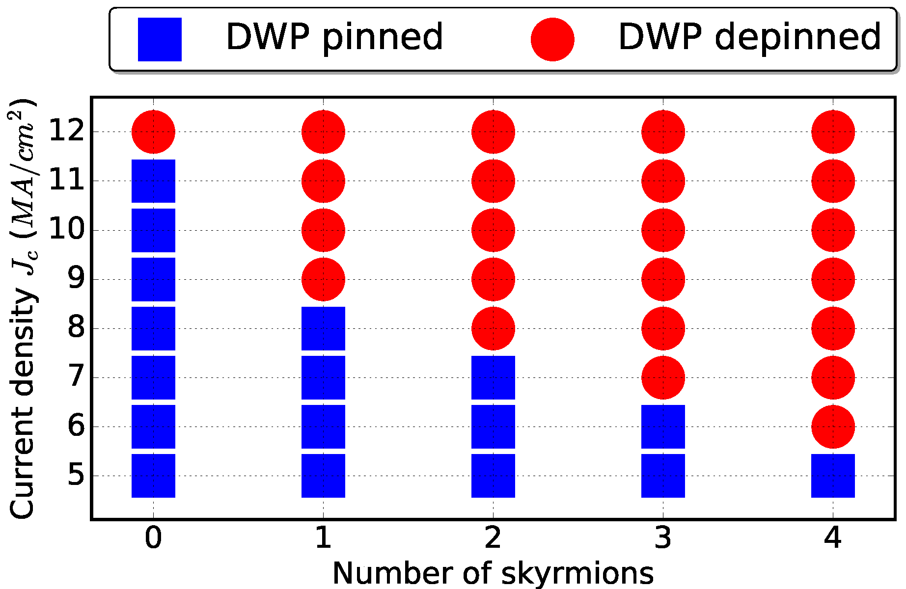
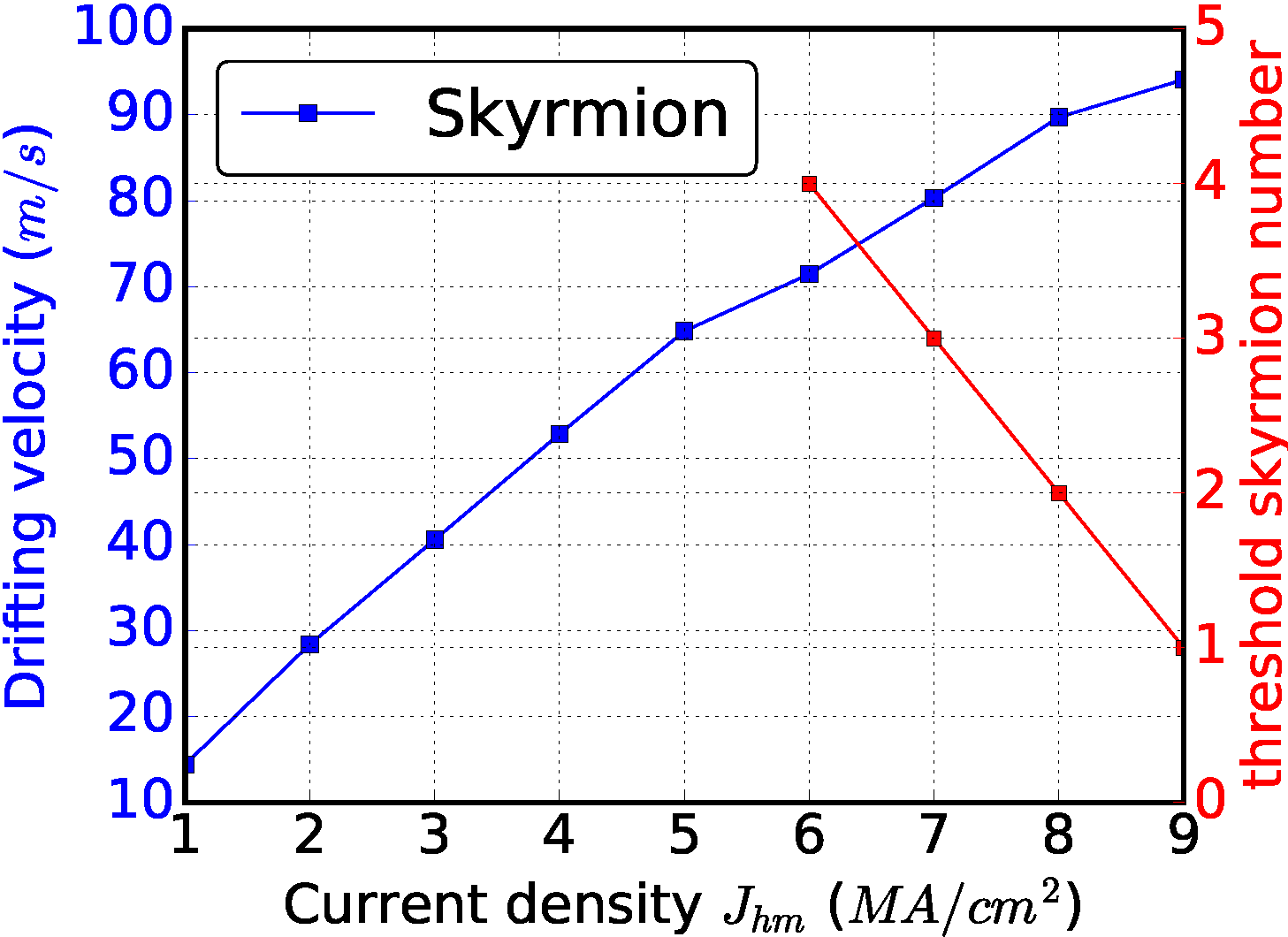
Such DWP pinning/depinning behavior at the notch determined simultaneously by driving current density and number of skyrmions is summarised in Fig. 4a. For larger number of skyrmions, the critical DWP depinning current density decreases due to the larger repulsion force from each individual skyrmion. Meanwhile, a lower driving current density requires more skyrmions to depin the DWP out of pinning site, where such quantity of skyrmions is defined as threshold skyrmion number. For example, if and the number of skyrmions is 2, the DWP is pinned. However, considering the same driving current but one more skyrmion in the nanotrack, the DWP is depinned. Therefore, the threshold skyrmion number is 3 for . Moreover, the relationship between skyrmion/DWP drifting velocity, threshold skyrmion number and driving current density is shown in Fig. 4b. It can be seen that the current-driven skyrmion drifting velocity positively correlates with driving current density, while the threshold skyrmion number reduces with increment of .
II-C Device modeling
We perform the micromagnetic simulation based on Object Oriented MicroMagnetic Framework (OOMMF). In this work, we focus on the Spin Hall Effect (SHE) induced skyrmion motion. The real-time magnetization dynamics are modeled by Landau-Lifshitz-Gilbert equation with spin transfer torque terms [23]:
| (3) |
| (4) |
where is the reduced plank constant, is the gyromagnetic ratio, is the thickness of magnetic film, is the non-adiabatic Spin transfer torque coefficient, and is the effective magnetic field.
The Dzyaloshinskii-Moriya Interaction (DMI) is applied with DMI extension module [23], which describes the energy density of DMI as [15]:
| (5) |
where is DMI constant, and , , are the components of normalized magnetization on x-, y- and z-axis respectively.
| Parameter | Value |
|---|---|
| Magnetic film dimension, | |
| Heavy metal dimension, | |
| rectangular notch dimension, | |
| Gilbert Damping Factor, | |
| Non-adiabatic STT factor, | |
| Spin Hall angle, | |
| Exchange stiffness, | |
| Perpendicular Magnetic Anisotropy, | |
| Saturation Magnetization, | |
| DMI constant, | |
| Mesh size, |
III Skyrmion-based Majority Logic Gate
Based on the previous discussion, it can be seen that a threshold-tunable step function could be implemented by such magnetic racetrack due to the dynamical interactions of skyrmions and domain wall pair, in which the skyrmions (presence or absence) are inputs and threshold could be tuned by the driving current density. In this section, a three-input Skyrmion-based Majority Logic Gate (SMLG) is proposed to leverage such unique property. Note that, majority gate is Boolean-complete and is able to implement any Boolean functions [24]. In the proposed SMLG, the binary input ‘1’ and ‘0’ are represented by the presence and absence of skyrmion, respectively. The output is indicated by the pinned- (‘0’) or depinned-DWP (‘1’). It is noteworthy that it is difficult to sense the existence of skyrmion due to its ultra-small dimension [21], which is one of the main limitations of skyrmion based logic [9] and memory designs [25]. In our proposed logic design, the output (i.e. domain wall pair) could be easily sensed using a sensing MTJ similar as other domain wall based logic designs [26].
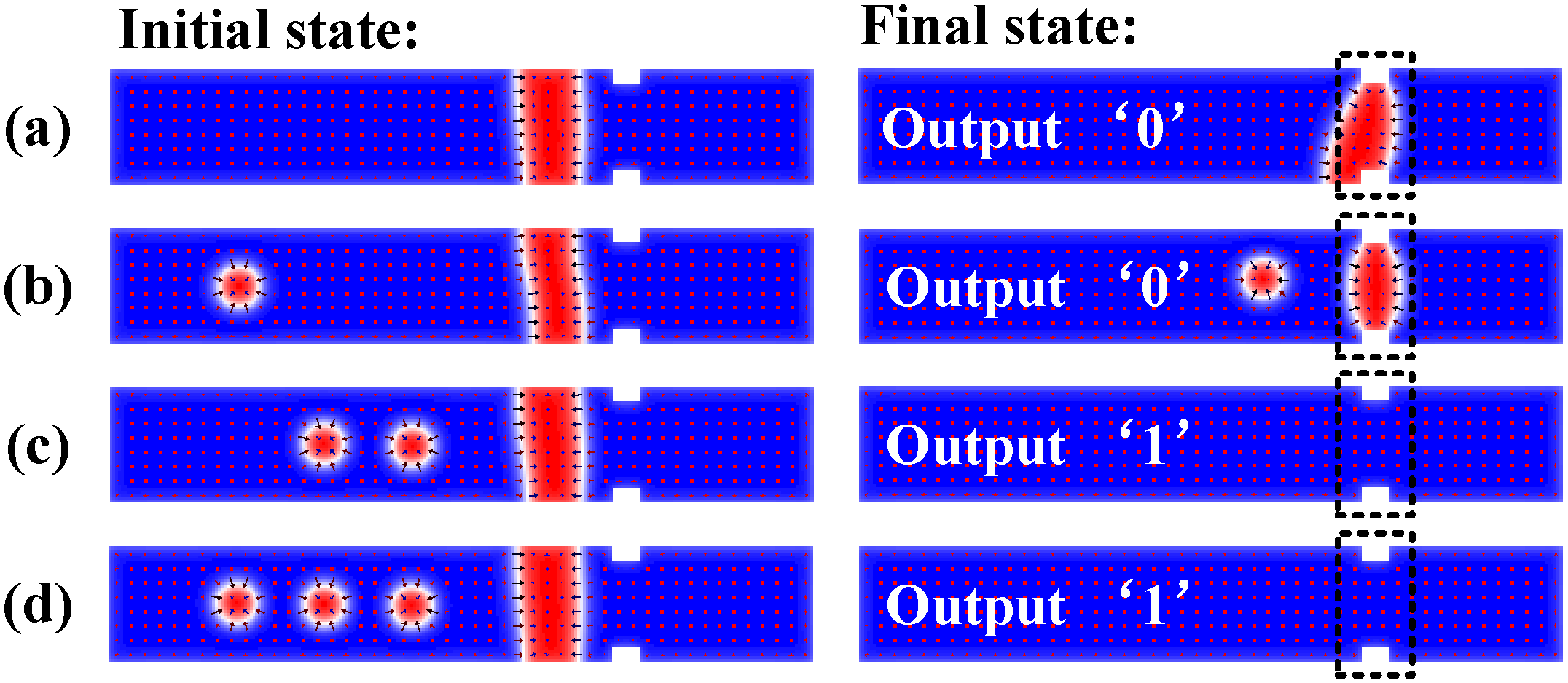
The output of an n-input Majority Gate (MG) (n is odd) is determined by majority of its inputs. For example, the output is ‘1’ only when more than () of the inputs are ‘1’. There are three inputs for the SMLG design, assuming input ‘A’, ‘B’ and ‘bias’ respectively. As reported in the previous section. II-B, the threshold skyrmion number is 2 corresponding to the current density of . Fig. 5 shows that if the number of input ‘1’s (i.e. number of skyrmions), is greater or equal than 2, the output is ‘1’ (i.e. DWP depinned), otherwise output is ‘0’. Therefore, such SMLG can also be configured as AND or OR logic through controlling the bias[24]. The truth table of AND and OR logic is tabulated in Table II.
| AND | OR | ||||||||
| A | B | Bias | DWP | Out | A | B | Bias | DWP | Out |
| 0 | 0 | 0 | pinned | 0 | 0 | 0 | 1 | pinned | 0 |
| 0 | 1 | 0 | pinned | 0 | 0 | 1 | 1 | depinned | 1 |
| 1 | 0 | 0 | pinned | 0 | 1 | 0 | 1 | depinned | 1 |
| 1 | 1 | 0 | depinned | 1 | 1 | 1 | 1 | depinned | 1 |
Although the presented work employs logic design as a case study, such behavior that accumulation of skyrmions causing the depinning of DWP shows interestingly similar functionality as the Integrate&Fire neuron of spiking neural network, in which the basic neuron function is to integrate the input synaptic spikes and generate a fire when reaching a threshold. Our future work is to explore such intrinsic match of skyrmion dynamics with neuromorphic computing model, which is promising to implement an ultra-dense and low power brain-inspired spiking neural network.
IV Conclusion
In this letter, we present the investigation of dynamic interaction between multiple skyrmions and domain wall pair in a nanotrack. We discover that domain wall pair could be pinned or depinned by the rectangular notch pinning site depending on both the number of skyrmions and driving current density. Such skyrmion and domain wall pair behavior intrinsically performs a threshold-tunable step function taken number of skyrmions as input variable. It can be leveraged to design a Skyrmion-based majority logic gate .
References
- [1] S. Mühlbauer, B. Binz, F. Jonietz, C. Pfleiderer, A. Rosch, A. Neubauer, R. Georgii, and P. Böni, “Skyrmion lattice in a chiral magnet,” Science, vol. 323, no. 5916, pp. 915–919, 2009.
- [2] X. Yu, Y. Onose, N. Kanazawa, J. Park, J. Han, Y. Matsui, N. Nagaosa, and Y. Tokura, “Real-space observation of a two-dimensional skyrmion crystal,” Nature, vol. 465, no. 7300, pp. 901–904, 2010.
- [3] W. Münzer, A. Neubauer, T. Adams, S. Mühlbauer, C. Franz, F. Jonietz, R. Georgii, P. Böni, B. Pedersen, M. Schmidt et al., “Skyrmion lattice in the doped semiconductor fe 1- x co x si,” Physical Review B, vol. 81, no. 4, p. 041203, 2010.
- [4] X. Yu, N. Kanazawa, Y. Onose, K. Kimoto, W. Zhang, S. Ishiwata, Y. Matsui, and Y. Tokura, “Near room-temperature formation of a skyrmion crystal in thin-films of the helimagnet fege,” Nature materials, vol. 10, no. 2, pp. 106–109, 2011.
- [5] S. Huang and C. Chien, “Extended skyrmion phase in epitaxial fege (111) thin films,” Physical review letters, vol. 108, no. 26, p. 267201, 2012.
- [6] W. Jiang, X. Zhang, G. Yu, W. Zhang, X. Wang, M. B. Jungfleisch, J. E. Pearson, X. Cheng, O. Heinonen, K. L. Wang et al., “Direct observation of the skyrmion hall effect,” Nature Physics, 2016.
- [7] K. Litzius, I. Lemesh, B. Krüger, P. Bassirian, L. Caretta, K. Richter, F. Büttner, K. Sato, O. A. Tretiakov, J. Förster et al., “Skyrmion hall effect revealed by direct time-resolved x-ray microscopy,” Nature Physics, 2016.
- [8] R. Tomasello, E. Martinez, R. Zivieri, L. Torres, M. Carpentieri, and G. Finocchio, “A strategy for the design of skyrmion racetrack memories,” Scientific Reports, vol. 4, p. 6784, 2014.
- [9] X. Zhang, M. Ezawa, and Y. Zhou, “Magnetic skyrmion logic gates: conversion, duplication and merging of skyrmions,” Scientific Reports, 2015.
- [10] X. Xing, P. W. Pong, and Y. Zhou, “Skyrmion domain wall collision and domain wall-gated skyrmion logic,” Physical Review B, vol. 94, no. 5, p. 054408, 2016.
- [11] S. Zhang, J. Wang, Q. Zheng, Q. Zhu, X. Liu, S. Chen, C. Jin, Q. Liu, C. Jia, and D. Xue, “Current-induced magnetic skyrmions oscillator,” New Journal of Physics, vol. 17, no. 2, p. 023061, 2015.
- [12] X. Zhang, Y. Zhou, M. Ezawa, G. Zhao, and W. Zhao, “Magnetic skyrmion transistor: skyrmion motion in a voltage-gated nanotrack,” Scientific reports, vol. 5, p. 11369, 2015.
- [13] Y. Huang, W. Kang, X. Zhang, Y. Zhou, and W. Zhao, “Magnetic skyrmion-based synaptic devices.” Nanotechnology, vol. 28, no. 8, p. 08LT02, jan 2017. [Online]. Available: http://www.ncbi.nlm.nih.gov/pubmed/28070023
- [14] W. Kang, Y. Huang, C. Zheng, W. Lv, N. Lei, Y. Zhang, X. Zhang, Y. Zhou, and W. Zhao, “Voltage controlled magnetic skyrmion motion for racetrack memory,” Scientific reports, vol. 6, 2016.
- [15] J. Sampaio, V. Cros, S. Rohart, A. Thiaville, and A. Fert, “Nucleation, stability and current-induced motion of isolated magnetic skyrmions in nanostructures,” Nature nanotechnology, vol. 8, no. 11, pp. 839–844, 2013.
- [16] A. Fert, V. Cros, and J. Sampaio, “Skyrmions on the track,” Nature nanotechnology, vol. 8, no. 3, pp. 152–156, 2013.
- [17] H. Yuan and X. Wang, “Domain wall pinning in notched nanowires,” Physical Review B, vol. 89, no. 5, p. 054423, 2014.
- [18] Y. Zhou and M. Ezawa, “A reversible conversion between a skyrmion and a domain-wall pair in junction geometry,” arXiv preprint arXiv:1404.3350, 2014.
- [19] G. Chen, “Spin-orbitronics: Skyrmion hall effect,” Nature Physics, 2017.
- [20] J. Iwasaki, M. Mochizuki, and N. Nagaosa, “Current-induced skyrmion dynamics in constricted geometries,” Nature nanotechnology, vol. 8, no. 10, pp. 742–747, 2013.
- [21] W. Kang, Y. Huang, X. Zhang, Y. Zhou, and W. Zhao, “Skyrmion-electronics: An overview and outlook,” Proceedings of the IEEE, vol. 104, no. 10, pp. 2040–2061, 2016.
- [22] X. Zhang, G. Zhao, H. Fangohr, J. P. Liu, W. Xia, J. Xia, and F. Morvan, “Skyrmion-skyrmion and skyrmion-edge repulsions in skyrmion-based racetrack memory,” arXiv preprint arXiv:1403.7283, 2014.
- [23] M. J. Donahue and D. G. Porter, OOMMF User’s guide. US Department of Commerce, Technology Administration, National Institute of Standards and Technology, 1999.
- [24] D. Fan, “Low power in-memory computing platform with four terminal magnetic domain wall motion devices,” in Nanoscale Architectures (NANOARCH), 2016 IEEE/ACM International Symposium on. IEEE, 2016, pp. 153–158.
- [25] W. Kang, C. Zheng, Y. Huang, X. Zhang, W. Lv, Y. Zhou, and W. Zhao, “Compact modeling and evaluation of magnetic skyrmion-based racetrack memory,” IEEE Transactions on Electron Devices, vol. PP, no. 99, pp. 1–9, 2017.
- [26] Z. He and D. Fan, “Energy efficient reconfigurable threshold logic circuit with spintronic devices,” IEEE Transactions on Emerging Topics in Computing, 2016.