Polarized disk emission from Herbig Ae/Be stars observed using Gemini Planet Imager: HD 144432, HD 150193, HD 163296, and HD 169142
Abstract
In order to look for signs of on-going planet formation in young disks, we carried out the first J-band polarized emission imaging of the Herbig Ae/Be stars HD 150193, HD 163296, and HD 169142 using the Gemini Planet Imager (GPI), along with new H band observations of HD 144432. We confirm the complex “double ring” structure for the nearly face-on system HD 169142 first seen in H-band, finding the outer ring to be substantially redder than the inner one in polarized intensity. Using radiative transfer modeling, we developed a physical model that explains the full spectral energy distribution (SED) and J- and H-band surface brightness profiles, suggesting that the differential color of the two rings from reddened starlight traversing the inner wall and differences in grain properties. In addition, we clearly detect an elongated, off-center ring in HD 163296 (MWC 275), locating the scattering surface to be 18 AU above the midplane at a radial distance of 77 AU, co-spatial with a ring seen at 1.3mm by ALMA linked to the CO snow line. Lastly, we report a weak tentative detection of scattered light for HD 150193 (MWC 863) and a non-detection for HD 144432; the stellar companion known for each of these targets has likely disrupted the material in the outer disk of the primary star. For HD 163296 and HD 169142, the prominent outer rings we detect could be evidence for giant planet formation in the outer disk or a manifestation of large-scale dust growth processes possibly related to snow-line chemistry.
=1
1 Introduction
While astronomers have detected thousands of exoplanets (2951 confirmed planets to date on exoplanets.org), we still lack a predictive theory of planet formation that can explain their distributions in mass, orbital characteristics, and dependence on host star properties. Many ingredients for planet formation – such as the streaming instability, dust growth, dead zones, gravitational instability, core accretion, planetary migration, and more – have been identified but there is no consensus as to their relative importance as numerical models struggle to match the increasingly rich and diverse constraints with only simple inputs.
Fortunately we have more than just the final distribution of exoplanetary systems to learn from. Indeed we can directly observe key stages of the planet formation process through high angular resolution imaging in star forming regions. The combination of infrared imaging and mm-wave imaging shows how the large and small grains can be decoupled by disk vortices in some cases(e.g., IRS Oph 48; van der Marel et al., 2013) or be more co-spatial in spiral arm structures in others(e.g. SAO 206462; Garufi et al., 2013; Pérez et al., 2014).
Some of the features seen in the outer disks can be explained by interactions with unseen giant planets within the disk (e.g., SAO 206462; Bae et al., 2016). Directed by theory, searches have so far not been able to confirm the presence of young exoplanets in most cases and some researchers look toward other explanations involving snow lines (Zhang et al., 2016) and/or dust evolution (Birnstiel et al., 2015). More generally, direct imaging surveys for exoplanets around a wider range of stars also are starting to provide constraints on the prevalence of giant planets. Galicher et al. (2016) report giant planets are rare beyond 20 AU (present for 1% of systems); if true, then perhaps the rings and gaps commonly seen in the outer regions of YSO disks are coming from something else (or possibly the young giant planets migrate inward as the disk evolves).
Within the next 10 years, astronomers will obtain dozens of high resolution images of young star disks in mm-wave emission (ALMA), scattered light (Subaru, GPI, SPHERE) and mid-infrared thermal emission (VLTI/MATISSE). Here we present four new deep observations of well-known Herbig Ae/Be stars in polarized scattered light using the Gemini Planet Imager. Our new data presently are the highest resolution and signal-to-noise images of complex features within 100 AU of these targets and we present a preliminary analysis and discuss our findings in the context of current debates on the giant planet formation in the outer solar system beyond 20 AU.
2 Observations and Data Processing
We report new imaging of Herbig Ae/Be stars using the Gemini Planet Imager (GPI; Macintosh et al., 2008, 2014; Poyneer et al., 2016) installed on Gemini South. In polarimetry mode (Perrin et al., 2015) with the adaptive optics system and an occulting spot, GPI can obtain high dynamic range imaging of scattered light from Y-K bands relying on the physics of scattering to deliver a distinctive polarization pattern.
This paper collects data from two separate observing runs, one in 2014 (GS-2014A-SV-412) and one in 2015 (GS-2015A-Q-49). For the data presented here, we utilized the standard GPI coronagraphic configurations (specifically ’J-coron’ and ’H-coron’), including use of a coronographic spot (0.184” diameter for J band and 0.246” diameter for H band) and appropriate Lyot and apodizing pupil masks. We chose integration times to just avoid saturation of light around the spot, ranging from 15 to 30 seconds. We coadded either 2 or 4 frames together to accumulate 1 minute of on-source exposure time per file, a limit imposed by the rotating field-of-view in the GPI design. We used the Wollaston prism mode and rotated the half-wave plate 22.5° between each 1 minute observation. Table 1 contains the information on the target stars while Table 2 contains the Observing Log.
2.1 Polarization Analysis
Here we outline the data reduction steps to extract polarimetric observables. The work was largely carried out using the IDL-based GPI pipeline version 1.4 along with custom routines written in IDL. See Perrin et al. (2014) and Millar-Blanchaer et al. (2016) for more detailed descriptions of the basic method outlined here.
Firstly, we searched the Gemini Data Archive for the best calibration files. Specifically, we created darks from files taken close in time and with the same integration time as used for the science data and the flats. We used the standard pipeline recipe “Calibration/Darks” for this purpose. Note that the darks and flats were not always taken on the same day as the science observations. We then followed this step by using the daytime flat calibration files to calibrate spot locations using recipe “Calibration/Calibrate Polarization Spots Locations - Parallel.” We found that some of the defaults for this recipe changed between pipeline 1.3 and 1.4 which caused this step to fail originally, but the spot calibration was successful after returning to the defaults from v1.3. At this stage we also used the recipe “Calibration/Create Low Spatial Frequency Polarized Flat-field” for use in later steps. Bad pixel maps and a few other calibration files were needed by the pipeline and these were downloaded from the Gemini GPI website.
Following these preliminaries, we proceed to reduce the actual science data. All the individual exposures taken with the Wollaston Prism were processed using a slightly modified recipe “PolarimetricScience/Simple Polarization Cube Extraction.” We removed the step that attempts to measure the flux using the satellite spots after concluding this procedure was not reliable enough for our use. This recipe created a series of polarization datacube (“podc”) files. At this stage, careful attention was paid that the center of the pattern was accurately measured by the pipeline using the primitive111”Primitive” is the term used by the GPI pipeline to refer to core analysis routines. “Measure Star Position from Polarimetry.” Unfortunately this algorithm, based on the Radon Transform (see description and tests in Wang et al., 2014), does fail when a companion is nearby (e.g., for HD 144432, HD 150193). A custom and interactive version of this primitive was written to allow detailed masking of the companion and its diffraction features. After testing the results of our routine against the standard primitive for single stars, we then re-analyzed all the polarization datacube files using our own algorithm, modifying the header keywords PSFCENTX, PSFCENTY in FITS extension 1. We estimated an extra 0.5 pixel error on the centroid estimates when a companion was present. While we were not able to locate the position of HD 144432B since it was slightly off-chip, we can report a new astrometric position for HD 150193B relative to A: 1.12″0.02″at PA 223°1°(compare to 1.10″0.03″ at PA 225.0°0.8° reported by Fukagawa et al., 2010).
Next, the individual files were grouped in chunks of 8 files each separated by a 22.5° rotation of the half-wave plate and then analyzed using a slightly modified version of the recipe “PolarimetricScience/Basic Polarization Sequence (From polarization datacubes).” In our version, we the primitive “Subtract Mean Stellar Polarization” in order to implement our own version later in the process. As an output of this step, the pipeline used a singular value decomposition (SVD) method (e.g., Perrin et al., 2015) to estimate the Stokes components from the set of 8 observations.
a 1% linearly polarized PSF will dominate over the polarized dust emission beyond 0.5” or so. We experimented with a few different methods for estimating the underlying stellar polarization before removing it. While other workers have chosen to use the signal either behind or just outside the coronagraphic spot (see the interesting study by Millar-Blanchaer et al., 2016), we used the azimuthally-averaged Stokes surface brightness profile to estimate residual linear polarization, extracting the median value of , , within 1.2” (for the single H-band dataset of HD 144432 we used a region within 0.4” based on visual inspection of the results). Note that using flux behind the occulting spot gives similar results but our procedure demonstrated less variance when applied to a large test dataset. Once we have the we can multiply this by the total intensity in each pixel to estimate the contamination and subtract these contributions from the linear polarization. For reference, we report the mean stellar linear polarization that we removed (all angles are degrees East of North): HD 144432 at , HD 150193 at , HD 163296 at , and HD 169142 at . For HD 163296 and HD 169142 the observed polarization angle varied as a function of parallactic angle suggesting that these measurements are partially still contaminated by uncorrected instrumental effects and not totally intrinsic. That said, generally our values are broadly consistent with measurements at similar wavelengths: HD 144432 at (Oudmaijer et al., 2001), HD 150193 at (Oudmaijer et al., 2001), HD 163296 at (Oudmaijer et al., 2001), and HD 169142 (Chavero et al., 2006). Also for comparison, Hales et al. (2006) made the following report: HD 144432 at , HD 150193 at , HD 169142 at .
Following subtraction of mean stellar polarization signal from the Stokes data cube (one for each group of 8 files), we then coadded multiple stokes datacubes spanning a range of parallactic angles. Lastly, we project the traditional Stokes components (oriented relative to North/East) onto a radial basis set based on the stellar position determined earlier in the processing. In this procedure (see derivation in Schmid et al., 2006; Avenhaus et al., 2014; Garufi et al., 2014; Millar-Blanchaer et al., 2016), linear polarization vectors that are azimuthally-oriented around the center are positive in space while radial vectors are negative. Similarly polarization vectors oriented 45 from this are found in the component. This projection is very practical since single-scattering should be oriented around the stellar position and produce purely positive signal, while noise can be both positive and negative. Furthermore, miscalibrations (especially in the inner PSF halo) will produce residual signal that can be used to assess data quality and guard against false conclusions. That said, we recognize the limitations of this presentation and refer to Canovas et al. (2015) and Dong et al. (2016) for more sophisticated discussion of polarization signatures for optically-thick, more edge-on disks.
| RA | Dec | 2MASSaaHere we refer to the number of frames used in the data reduction, where a frame consists of Ncoadds images coadded with individual exposures times of Tint seconds at a single half-wave plate position. A few recorded frames were unusable due to clouds or poor guiding behind the occulting spot. | Teff | Meeusccfootnotemark: | Distance | |||||
| HD Number | Alias | J2000 | J2000 | R | J | H | Ks | (K)bbSeeing column is value reported in headers based on DIMM measurements. | Group | (pc) |
| HD 144432A | 7.8 | 7.1 | 6.5 | 5.9 | 7500 | IIa | 145ddfootnotemark: | |||
| HD 150193A | MWC 863A | 8.4 | 6.9 | 6.2 | 5.5 | 9500 | IIa | 150eefootnotemark: | ||
| HD 163296 | MWC 275 | 6.9 | 6.2 | 5.5 | 4.8 | 9200 | IIa | 119fffootnotemark: | ||
| HD 169142 | MWC 925 | 8.2 | 7.3 | 6.9 | 6.4 | 7500 | Ib | 145ggfootnotemark: | ||
| Refs. (a) Skrutskie et al. (2006) (b) Alecian et al. (2013) (c) Meeus et al. (2001) (d) Pérez et al. (2004) | ||||||||||
| (e) Feigelson et al. (2003) (f) van Leeuwen (2007) (g) Sylvester et al. (1996) | ||||||||||
| UT Date | Target Name | Filter | Tint (sec) | Ncoadds | NFramesaaHere we refer to the number of frames used in the data reduction, where a frame consists of Ncoadds images coadded with individual exposures times of Tint seconds at a single half-wave plate position. A few recorded frames were unusable due to clouds or poor guiding behind the occulting spot. | Airmass | Seeing (″)bbSeeing column is value reported in headers based on DIMM measurements. |
|---|---|---|---|---|---|---|---|
| 2014 April 23 | HD 150193A | J | 29.10 | 2 | 16 | 1.101.16 | 0.460.68 |
| 2014 April 24 | HD 150193A | J | 29.10 | 2 | 16 | 1.091.16 | 0.650.86 |
| 2014 April 24 | HD 163296 | J | 14.55 | 4 | 32 | 1.031.07 | 0.480.84 |
| 2014 April 25 | HD 169142 | J | 29.10 | 2 | 64 | 1.001.40 | 0.581.11 |
| 2014 April 25 | HD 91538 | J | 1.5 | 4 | 8 | 1.0211.023 | 0.610.76 |
| 2015 July 9 | HD 144432A | H | 29.10 | 2 | 24 | 1.111.21 | 0.891.40 |
| 2015 July 9 | HR 6572 | H | 1.5 | 4 | 14 | 1.321.37 | 0.710.79 |
2.2 Flux Calibration
Our data were taken during the early stages of Gemini Planet Imager commissioning and a full set of flux calibration data were not taken. It has been difficult to independently verify some important throughput estimates needed to calibrate the surface brightness in physical units. For J band, we used the PSF source HD 91538 (J mag 5.42) observed on 2014 Apr 25 with the Wollaston prism in J band but which had the adaptive optics loop off and had the coronagraph spot, apodizer, and Lyot stop out. Laboratory tests demonstrated that we expect 2.69 less light through the system when inserting the apodizer and Lyot stop for J band mode and we applied this factor when calibrating our flux. Unfortunately the companion stars for HD 144432 and HD 150193 were both either saturated or partially outside the field-of-view and could not be used for flux calibration. For the 2015 H band data, we requested a PSF star observation to be taken with the same occulting spot, apodizer, and Lyot stop as the polarization target and HR 6572 (H mag 5.74) was observed with AO loop off. Since these calibrations could be affected by cloud or atmospheric conditions . A more robust flux calibration procedure will be adopted in future work since comparisons between J,H,K polarized surface brightness provide critical constraints in probing dust size distributions.

3 Basic Results
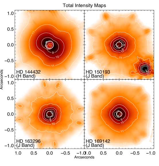
We present the total intensity maps in Figure 1, Stokes maps in Figure 2, Stokes maps in Figure 3, and their corresponding mean radial profiles in Figure 4. Each figure has an explanation of how the images are scaled and presented. We generally present the absolute value of the and maps with logarithmic surface brightness contours.
First we discuss the total intensity maps in Figure 1. We see a depression in the center of the PSF because of the occulting mask, marked by a circle. We see the PSF was rather elongated for the HD 144432 observation while more circularly-symmetric in the other observations One can see diffraction spikes from the 1.4″companion near the top of the HD 144432 frame and one can also see the slightly-saturated companion to HD 150193 located 1.120.02″at PA 2231°relative to the primary. The other spots are due to either residual “waffle mode” from the adaptive optics system or the diffractive satellite spots induced by GPI for registration of the bright star behind the coronagraph. We assume this light is from the central source PSF and that we can not extract the scattered light intensity from circumstellar dust without using the polarization signature.
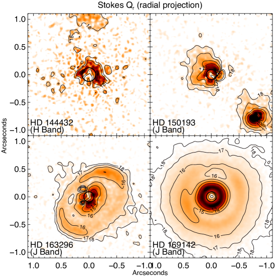
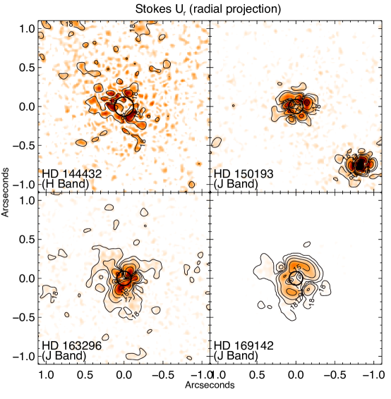
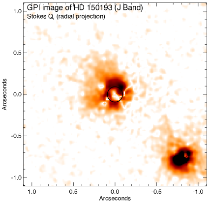
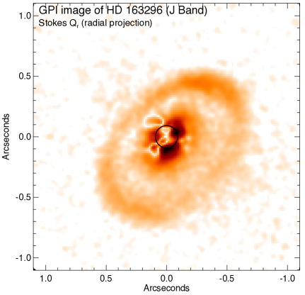
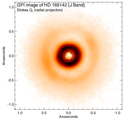
The main results of this work are best seen in Figure 2, where the radially-projected Stokes maps are presented. It is useful to compare these images to the images in Figure 3 since residuals in the map indicate the level of systematic errors in our suppression technique, recalling the caveat that we are not observing more edge-on systems (as discussed by Canovas et al., 2015). We will discuss briefly each target separately.
-
•
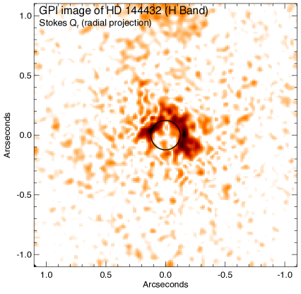
HD 144432. We see no convincing sign of scattered light at H band since the level and pattern of is similar to that seen in . While the surface-brightness limits within 0.25″ are only about 16.5 mag/square arcsecond, our upper limits beyond 0.3” reach about 20 mag/square arcsecond. We could not locate any previous measurements to compare. HD 144432 has amongst the smallest far-IR excess from our sample. We suspect the presence of the nearby companion is responsible for truncating the outer disk, although this is difficult to prove without knowledge of the full orbit of HD 144432B.
-
•
HD 150193. There is slight excess emission seen to the North-East beyond about 0.2 with surface brightness of 17 mag/square arcsecond. This pattern is not seen in the emission and appears to be real, although some caution is advised since this source has by the far highest intrinsic stellar polarization (3%) and thus calibration errors may be larger than for other targets. Garufi et al. (2014) reported an upper limit of 0.8 mJy/square arcsecond at this radius at H band which corresponds to about 15 mag/square arcsecond, not incompatible with our new detection even accounting for the for this star. We note that HD 150193 also has small far-IR excess like HD 144432, quite possibly due to the disk-disrupting presence of stellar companions in both systems.
-
•
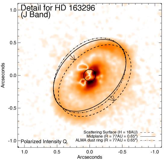
HD 163296. In the image, we clearly detect a full outer ring (not centered on the star) with major axis of 0.65″ oriented along PA of 136° with peak polarized intensity of 15 mag/square arcsecond, confirming the lower SNR detection by Garufi et al. (2014) at H and K. Only with our new high-SNR GPI data can we clearly see the ring is off-center. Within 0.4″, there does appear to be excess emission in the inner region beyond the residual seen in . This excess is elongated the same way as the outer ring giving further evidence that we are indeed seeing scattered light from dust within the inner disk. Garufi et al. (2014) found the peak K band (H band) surface brightness of the outer ring to be 0.5 (0.15) mJy/square arcsecond which is 15.2 (17.1) mag/square arcsecond. and we offer a simple interpretation for the off-center ring in §5.
-
•
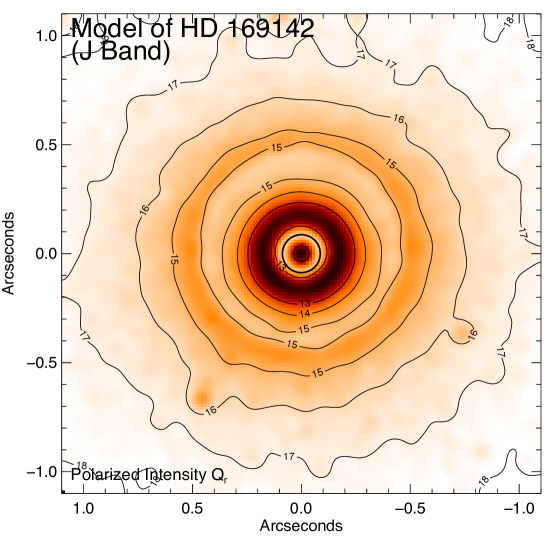
HD 169142. In the image, we clearly detect the inner ring and outer disk first reported by Quanz et al. (2013) at H band. Our new J band image is much higher quality and more comparable to the recent Subaru polarization imaging by Momose et al. (2015) at H band; the peak of the inner ring is well distinguished from the coronagraphic spot (see profiles in Figure 4 in our data). We also see a gap in the outer disk to the north (see Figure 2). Momose et al. (2015) found peak surface brightness level of the outer disk to be 4 mJy/square arcsecond, or 13.5 mag/square arcsecond. At J band, we find a peak surface brightness about 14.5 mag/square arcsecond. Note that the inner edge of the ring is not so clearly resolved by Momose et al. (2015) as it is for our work and Quanz et al. (2013). Specifically we find the inner ring has a sharp inner edge with radius of 0.18″(25 AU), the outer disk has peak surface brightness at 0.51″(75 AU), with a local dip in brightness at 0.38″(55 AU) – . The J-H color of the inner ring in our image is 0.4, similar to the color of the star itself, while the outer disk has a mean color J-H1.0, much redder. We describe our attempts to model the disk of HD 169142 in the next section.
4 Radiative transfer modeling of HD 169142
We used the torus radiative transfer code (Harries, 2000; Harries et al., 2004; Harries, 2011) to model HD 169142. The code uses the Monte Carlo (MC) radiative equilibrium method of Lucy (1999), and an adaptive mesh that is constructed to adequately resolve sharp opacity gradients. The torus code has been extensively benchmarked (Harries et al., 2004; Pinte et al., 2009). In the following section we describe the properties of the circumstellar disk model and then detail the optimization process used to identify the best fit. Finally we critically appraise our model solution.
4.1 The disk structure
The disk density in cylindrical coordinates is given by
| (1) |
where is a fiducial density, is the density power-law index, and the scale-height is given by
| (2) |
where is the scale-height at and is the flaring index. The value of is found from
| (3) |
where and are the inner and outer disk radii respectively.
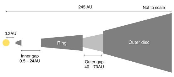
Previous authors (Quanz et al., 2013; Osorio et al., 2014; Wagner et al., 2015; Momose et al., 2015; Seok & Li, 2016) have identified the main components of the disk from analyses of the SED and scattered light imaging, namely: (i) a small “inner disk” that provides the near-IR excess , (ii) a gap that is apparently very low density between the innermost disk and AU, a (iii) a narrow ring of material between AU and AU (we refer here to this as the “inner ring”), (iv) a second gap, with a reduced (but non-negligible) density, spanning the region between AU and AU, and finally (v) a flared, “outer disk” extending from AU out to around 245 AU.
Much of the radiation observed results from heating of the inner edge of the disk, and outer walls of the gap by stellar radiation, whilst the mid-planes of the walls at and AU are shadowed by the inner disk and the ring respectively. The complex nature of this interaction leads to substantial degeneracies between the free parameters of the model, for example increasing the scale-height at AU or reducing the wall scale-height at 0.2 AU will lead to an increase in the mid-IR flux, since both changes lead to a greater area exposed to direct stellar heating (although the latter change will lead to a reduction in the near-IR excess). Naturally this complicated disk model means that there are many free parameters (see Table 3), and our initial aim was to fix as many of these at plausible values prior to a formal best-fit procedure.
4.2 Determining the best fit model
We adopted the distance to HD 169142 of 145 pc from Sylvester et al. (1996) and the stellar parameters from Manoj et al. (2006). We used a Kurucz model atmosphere of appropriate and to represent the photospheric emission. See Table 3 for full set of assumptions.
For the dust, Draine & Lee (1984) silicate grains were used for our disk model, with grain size populations described by the usual power-law distribution (Mathis et al., 1977)
| (4) |
where is the number density of grains with a size . We used two distinct grain-size populations (small and large) whose properties are listed in Table 3. Since there is no obvious 10 m silicate feature in the SED, we concluded that the consists of large grains only, whereas over the rest of the disk we invoke grain settling, with the large grains having a scale-height that is half the local gas scale-height, and the . Thus the midplane of the disk is dominated by large grains, and the scattering region of the upper disk consists of small grains.
The location of the inner disk was fixed at 0.2 AU, and the disk scale-height at that radius was a free-parameter of the model (the varying of which allows a fit to the near-IR excess in the SED). The locations of the two gap walls is quite well determined from the peaks in the polarized surface brightness profiles at and , and our preliminary modeling, and we fixed these at 24 AU and 70 AU. The radius of the inner gap is not strongly constrained and we fixed this at 0.5 AU, whilst the inner radius of the outer gap is quite well constrained by the polarized surface brightness profiles and we fixed this at 40 AU. The outer disk radius was fixed at 245 AU. The disk mass and flaring index are quite strongly constrained by the far-IR and millimeter data points in the SED, and we found that a disk gas mass of 0.05 and a flaring parameter of 1.09 gave a good fit. We choose to use a canonical surface density fall off of following Momose et al. (2015).
The inner gap density was set to the floor density of the radiation transfer calculation ( g cm-3), however the outer gap is clearly visible in both scattered light images, and therefore must have a non-negligible density. We therefore chose to parameterize the density in the gap () by a simple scaling factor where
| (5) |
where is the density calculated from Equation 1 and Equation 2 using the scale-height at 70 AU, and .
The free parameters in the model are now the scale-heights of the inner disk, the ring, and the outer disk, the density in the outer gap, and the flaring parameter . We wished to determine the best fit in the most objective way possible, and therefore we chose to fit the and polarized intensity profiles222H band images from Quanz et al. (2013) were kindly provided by Dr. Quanz. and the SED simultaneously. A cartoon schematic of our disk mode can be found in Figure 5.
After fixing some parameters as discussed above, we used a generic algorithm to search the remaining parameter space. We modified the pikaia routine by Charbonneau (1995) to call a bespoke (i.e., custom) goodness-of-fit function. This function creates a torus input deck containing the fixed and free parameters, and runs torus in a parallel mode for speed. Once torus has completed, the function generates and band azimuthally-averaged polarized intensity profiles from the appropriate images, and also reads in the simulated SED. Finally the routine calculates a reduced value by comparison with the data and returns the inverse of this (pikaia expects a goodness-of-fit value that is numerically larger the better the fit). We operated pikaia in a full-generational replacement mode with 100 individuals per generation and searched parameter space for 50 generations.
| Parameter | Value | Description |
| Stellar parameters | ||
| Stellar radius, | 2.2 R⊙ | Manoj et al. (2006) |
| Effective temperature, | 8100 K | Manoj et al. (2006) |
| Stellar mass, | 2 M⊙ | Manoj et al. (2006) |
| Distance | 145 pc | Sylvester et al. (1996) |
| 0.5 | Dent et al. (2006) | |
| Disk parameters | ||
| Inclination, | 13∘ | Panić et al. (2008) |
| Disk mass, | 0.05 M⊙ | Refined |
| Disk flaring index, | 1.09 | Refined |
| Radial density index, | 2.09 | Refined |
| Inner disk radius, | 0.2 AU | Fixed |
| Scale-height at inner radius | 0.006 AU | Fitted |
| Outer disk radius, | 245 AU | Fixed |
| Inner disk gap range | 0.5–24 AU | Refined |
| Scale-height at 24 AU | 1.14 AU | Fitted |
| Inner gap density | g cm-3 | Fixed |
| Outer disk gap range | 40–70 AU | Fixed |
| Scale-height at 40 AU | 4.06 AU | Fitted |
| Outer gap density scaling () | 0.15 | Fitted |
| Grain properties, small grains | ||
| Grain type | Silicates | Draine & Lee (1984) |
| Min grain size, | 0.01 m | Fixed |
| Max grain size, | 1 m | Fixed |
| Grain properties, large grains | ||
| Grain type | Silicates | Draine & Lee (1984) |
| Min grain size, | 5 m | Fixed |
| Max grain size, | 1000 m | Fixed |
4.3 Results
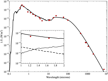
The best fit parameters are listed in Table 3 and a model image of the polarized intensity at J band can be found in Figure 6. One can see the major features of the GPI image are reproduced by comparing to the data presented in Figure 2. The agreement with the SED is also satisfactory (see left panel Figure 7). The fit is poorest at around 60 m. We note that this part of the SED arises primarily from the inner wall of the outermost part of the disk (corresponding to the second maximum in the surface brightness profiles at 0.55″). A better fit to the SED at this point is possible by changing the scale height of the inner ring (in order that the wall sees more direct stellar flux) but this would compromise the surface brightness profile fit.
We also show a detailed comparison of fit to the polarized surface brightness profiles at J and H band in the right panel of Figure 7. These profiles are an adequate match to the observations in terms of both the inner wall of the ring (the peak in the surface brightness at around 0.2″) and in the gap (the minimum at around 0.35″) although improvement could be made with further model complications. Note that the gap is not completely empty () as first noted by Quanz et al. (2013) and confirmed through the modelling of Wagner et al. (2015). For scenarios in which the gap is produced by a companion, the degree of clearing, or equivalently, the density contrast between the gap and the unperturbed disk, will be a function of both disk properties and companion properties. This dependence is complicated, but can provide constraints on possible companions, and should be pursued further in future work.
We find the power-law of the brightness profiles out to 1″ is well matched by the model, and strongly constrains the flaring power law index (). The relative brightness of the and profiles in the model shows reasonable agreement with the data, although the amount of differential reddening between the two rings is not fully reproduced.
If one only considers the polarized intensity, the observed reddening of the outer disk could be interpreted in terms of a size-dependent scattering coefficient. We expect small grains (0.1m) to behave like Rayleigh scatterers and be relatively blue when looking at the near-infrared J,H,K bands. However, for distributions with some medium-sized grains (1m), we start to see lower polarization fraction for band compared to and bands. Thus one could qualitatively interpret our observed reddening as the presence of larger grains in the outer disk and small grains in the inner ring.
we do not find evidence that the inhomogeneities in the inner ring are causing radial shadowing that can explain the azimuthal variations in brightness around the outer disk. In this paper, we will not speculate on whether the dip in brightness at 55AU can be related to the presence of a forming planet in this system but have focused on describing our new high-quality imaging data which shall be used in future detailed modeling efforts.


5 Discussion of HD 163296 ring
Garufi et al. (2014) first discovered evidence for an outer ring around HD 163296 but the data quality was marginal, just clearly seeing the SE and NW lobes. Here we see for the first time the full ring and can see the outline of the ring is strongly off-center (0.1”) from the star (see Figure 9).
While planets on eccentric orbits can produce off center debris disk rings we instead pursue the interpretation that dust scattering off of upper layers of an inclined, disk will cause the ring to appear off-center due to the viewing angle . We first adopted the disk inclination and position angle measured by Tannirkulam et al. (2008) using the CHARA interferometer observations of the inner disk (inclination 48°, PA 136°) and visually fit the radius of the ellipse and the height above the midplane for the scattering layer of dust. We mark these ellipses for ″=77AU and AU on the plot and find good agreement with the shape and orientation of the observed ring
Recently, Zhang et al. (2016) modeled ALMA 1.3mm data and suggested the presence of a local bright ring (one of three) of dust emission located at 0.65”(=77AU), just inside the CO snow line observed at 90AU. that the small grains responsible for scattering near-infrared light at 18AU above the midplane are actually located directly above the larger grains observed in the mid-plane by ALMA. If dust emission is enhanced just inside the CO snow line we see that both small and large grains are contributing.
This observation could have important consequences for modeling outer disk structures, especially when one considers that HD 169142 also shows an outer ring at a similar distance from the star – although no measurement of its CO snow line has been made yet. We await high resolution ALMA images of both CO lines and mm-wave continuum to make these possible links between dust populations and snow lines more durable.
6 Conclusions
Here we have presented new, high signal-to-noise observations of HD 144432, HD 150193, HD 163296, and HD 169142 using polarized imaging of the Gemini Planet Imager. We detected little or no scattered light around HD 144432 and HD 150193, two stars with nearby stellar companions that likely caused truncation of the outer disk. GPI revealed an off-center ring around HD 163296 which can be understood as scattering off the upper layers of an outer dust ring that is also seen by ALMA. Lastly, we contribute a new high-resolution image of HD 169142 that probes the structures of the two outer rings with unprecedented angular resolution and dynamic range, resulting in the first detection of strong differential color between the two rings. The multiple rings seen for these last two objects, as well as other Herbig Ae/Be stars , need to be placed in the context of the expected ice lines. New ALMA CO imaging, linked with polarized scattered light imaging, should soon hopefully answer the question “Are dust rings in the outer disks of Herbigs due to ice line chemistry, forming giant exoplanets, or something else?”
Appendix A Additional Figures
In order to aid other researchers in comparing our results to images taken at other wavelengths, we provide reference figures (see Figures 10 & 11) here of our polarized intensity surface brightness maps without contours or distracting labels.
References
- Alecian et al. (2013) Alecian, E., Wade, G. A., Catala, C., et al. 2013, MNRAS, 429, 1001
- ALMA Partnership et al. (2015) ALMA Partnership, Brogan, C. L., Pérez, L. M., et al. 2015, ApJ, 808, L3
- Avenhaus et al. (2014) Avenhaus, H., Quanz, S. P., Schmid, H. M., et al. 2014, ApJ, 781, 87
- Bae et al. (2016) Bae, J., Zhu, Z., & Hartmann, L. 2016, ApJ, 819, 134
- Birnstiel et al. (2015) Birnstiel, T., Andrews, S. M., Pinilla, P., & Kama, M. 2015, ApJ, 813, L14
- Birnstiel et al. (2010) Birnstiel, T., Dullemond, C. P., & Brauer, F. 2010, A&A, 513, A79
- Boss (1997) Boss, A. P. 1997, Science, 276, 1836
- Brandt et al. (2014) Brandt, T. D., McElwain, M. W., Turner, E. L., et al. 2014, ApJ, 794, 159
- Brown (2012) Brown, M. E. 2012, Annual Review of Earth and Planetary Sciences, 40, 467
- Canovas et al. (2015) Canovas, H., Ménard, F., de Boer, J., et al. 2015, A&A, 582, L7
- Canovas et al. (2016) Canovas, H., Hardy, A., Zurlo, A., et al. 2016, ArXiv e-prints, arXiv:1606.07087
- Carmona et al. (2007) Carmona, A., van den Ancker, M. E., & Henning, T. 2007, A&A, 464, 687
- Charbonneau (1995) Charbonneau, P. 1995, ApJS, 101, 309
- Chavero et al. (2006) Chavero, C., Gómez, M., Whitney, B. A., & Saffe, C. 2006, A&A, 452, 921
- Currie et al. (2015) Currie, T., Cloutier, R., Brittain, S., et al. 2015, ApJ, 814, L27
- de Boer et al. (2016) de Boer, J., Salter, G., Benisty, M., et al. 2016, A&A, 595, A114
- de Gregorio-Monsalvo et al. (2013) de Gregorio-Monsalvo, I., Ménard, F., Dent, W., et al. 2013, A&A, 557, A133
- Dent et al. (2006) Dent, W. R. F., Torrelles, J. M., Osorio, M., Calvet, N., & Anglada, G. 2006, MNRAS, 365, 1283
- Dong et al. (2016) Dong, R., Fung, J., & Chiang, E. 2016, ApJ, 826, 75
- Draine & Lee (1984) Draine, B. T., & Lee, H. M. 1984, ApJ, 285, 89
- Dullemond & Monnier (2010) Dullemond, C. P., & Monnier, J. D. 2010, ARA&A, 48, 205
- Feigelson et al. (2003) Feigelson, E. D., Lawson, W. A., & Garmire, G. P. 2003, ApJ, 599, 1207
- Fukagawa et al. (2010) Fukagawa, M., Tamura, M., Itoh, Y., et al. 2010, PASJ, 62, 347
- Galicher et al. (2016) Galicher, R., Marois, C., Macintosh, B., et al. 2016, ArXiv e-prints, arXiv:1607.08239
- Garufi et al. (2014) Garufi, A., Quanz, S. P., Schmid, H. M., et al. 2014, A&A, 568, A40
- Garufi et al. (2013) Garufi, A., Quanz, S. P., Avenhaus, H., et al. 2013, A&A, 560, A105
- Ginski et al. (2016) Ginski, C., Stolker, T., Pinilla, P., et al. 2016, A&A, 595, A112
- Guidi et al. (2016) Guidi, G., Tazzari, M., Testi, L., et al. 2016, A&A, 588, A112
- Hales et al. (2006) Hales, A. S., Gledhill, T. M., Barlow, M. J., & Lowe, K. T. E. 2006, MNRAS, 365, 1348
- Harries (2000) Harries, T. J. 2000, MNRAS, 315, 722
- Harries (2011) —. 2011, MNRAS, 416, 1500
- Harries et al. (2004) Harries, T. J., Monnier, J. D., Symington, N. H., & Kurosawa, R. 2004, MNRAS, 350, 565
- Hashimoto et al. (2012) Hashimoto, J., Dong, R., Kudo, T., et al. 2012, ApJ, 758, L19
- Isella et al. (2016) Isella, A., Guidi, G., Testi, L., et al. 2016, Physical Review Letters, 117, 251101
- Johansen et al. (2007) Johansen, A., Oishi, J. S., Mac Low, M.-M., et al. 2007, Nature, 448, 1022
- Lucy (1999) Lucy, L. B. 1999, A&A, 344, 282
- Maaskant et al. (2013) Maaskant, K. M., Honda, M., Waters, L. B. F. M., et al. 2013, A&A, 555, A64
- Macintosh et al. (2014) Macintosh, B., Graham, J. R., Ingraham, P., et al. 2014, Proceedings of the National Academy of Science, 111, 12661
- Macintosh et al. (2008) Macintosh, B. A., Graham, J. R., Palmer, D. W., et al. 2008, in Proc. SPIE, Vol. 7015, Adaptive Optics Systems, 701518
- Maire et al. (2014) Maire, J., Ingraham, P. J., De Rosa, R. J., et al. 2014, in Proc. SPIE, Vol. 9147, Ground-based and Airborne Instrumentation for Astronomy V, 914785
- Manoj et al. (2006) Manoj, P., Bhatt, H. C., Maheswar, G., & Muneer, S. 2006, ApJ, 653, 657
- Mathis et al. (1977) Mathis, J. S., Rumpl, W., & Nordsieck, K. H. 1977, ApJ, 217, 425
- Meeus et al. (2001) Meeus, G., Waters, L. B. F. M., Bouwman, J., et al. 2001, A&A, 365, 476
- Millar-Blanchaer et al. (2016) Millar-Blanchaer, M. A., Perrin, M. D., Hung, L.-W., et al. 2016, ArXiv e-prints, arXiv:1609.08691
- Momose et al. (2015) Momose, M., Morita, A., Fukagawa, M., et al. 2015, PASJ, 67, 83
- Müller et al. (2011) Müller, A., Carmona, A., van den Ancker, M. E., et al. 2011, A&A, 535, L3
- Oppenheimer et al. (2008) Oppenheimer, B. R., Brenner, D., Hinkley, S., et al. 2008, ApJ, 679, 1574
- Osorio et al. (2014) Osorio, M., Anglada, G., Carrasco-González, C., et al. 2014, ApJ, 791, L36
- Oudmaijer et al. (2001) Oudmaijer, R. D., Palacios, J., Eiroa, C., et al. 2001, A&A, 379, 564
- Panić et al. (2008) Panić, O., Hogerheijde, M. R., Wilner, D., & Qi, C. 2008, A&A, 491, 219
- Pérez et al. (2014) Pérez, L. M., Isella, A., Carpenter, J. M., & Chandler, C. J. 2014, ApJ, 783, L13
- Pérez et al. (2004) Pérez, M. R., van den Ancker, M. E., de Winter, D., & Bopp, B. W. 2004, A&A, 416, 647
- Perrin et al. (2014) Perrin, M. D., Maire, J., Ingraham, P., et al. 2014, in Proc. SPIE, Vol. 9147, Ground-based and Airborne Instrumentation for Astronomy V, 91473J
- Perrin et al. (2015) Perrin, M. D., Duchene, G., Millar-Blanchaer, M., et al. 2015, ApJ, 799, 182
- Pinte et al. (2009) Pinte, C., Harries, T. J., Min, M., et al. 2009, A&A, 498, 967
- Pollack et al. (1996) Pollack, J. B., Hubickyj, O., Bodenheimer, P., et al. 1996, Icarus, 124, 62
- Poyneer et al. (2016) Poyneer, L. A., Palmer, D. W., Macintosh, B., et al. 2016, Appl. Opt., 55, 323
- Quanz et al. (2013) Quanz, S. P., Avenhaus, H., Buenzli, E., et al. 2013, ApJ, 766, L2
- Quillen (2006) Quillen, A. C. 2006, MNRAS, 372, L14
- Schmid et al. (2006) Schmid, H. M., Joos, F., & Tschan, D. 2006, A&A, 452, 657
- Seok & Li (2016) Seok, J. Y., & Li, A. 2016, ApJ, 818, 2
- Skrutskie et al. (2006) Skrutskie, M. F., Cutri, R. M., Stiening, R., et al. 2006, AJ, 131, 1163
- Stolker et al. (2016) Stolker, T., Dominik, C., Min, M., et al. 2016, ArXiv e-prints, arXiv:1609.09505
- Sylvester et al. (1996) Sylvester, R. J., Skinner, C. J., Barlow, M. J., & Mannings, V. 1996, MNRAS, 279, 915
- Tanaka et al. (2002) Tanaka, H., Takeuchi, T., & Ward, W. R. 2002, ApJ, 565, 1257
- Tannirkulam et al. (2008) Tannirkulam, A., Monnier, J. D., Harries, T. J., et al. 2008, ApJ, 689, 513
- Turner & Sano (2008) Turner, N. J., & Sano, T. 2008, ApJ, 679, L131
- van der Marel et al. (2013) van der Marel, N., van Dishoeck, E. F., Bruderer, S., et al. 2013, Science, 340, 1199
- van Leeuwen (2007) van Leeuwen, F. 2007, A&A, 474, 653
- Wagner et al. (2015) Wagner, K. R., Sitko, M. L., Grady, C. A., et al. 2015, ApJ, 798, 94
- Wang et al. (2014) Wang, J. J., Rajan, A., Graham, J. R., et al. 2014, in Proc. SPIE, Vol. 9147, Ground-based and Airborne Instrumentation for Astronomy V, 914755
- Zhang et al. (2016) Zhang, K., Bergin, E. A., Blake, G. A., et al. 2016, ApJ, 818, L16