A comparison of C-shaped and brush armature performance
Abstract
The most important part of a railgun launch package is the armature where the electromagnetic force is generated leading to the acceleration of the launch package. In case of metal armatures, the most commonly used armature types are the C-shape and the multi-fiber brush technology. However, rarely both armature types were systematically compared under similar experimental conditions. That is why we constructed launch packages based on the C-shaped and brush armature technology with comparable armature and payload mass. With these launch packages a series of experiments were performed in an energy range between 0.8 MJ and 1.13 MJ corresponding to a speed range between 950 m/s and 1400 m/s. The results of the experiments were then analyzed qualitatively and quantitatively. On the one hand our results show that the total losses are higher for the C-shaped armature technology than for the brush aramture technology. On the other hand our results show that launch packages based on the C-shaped technology convert better electrical energy into kinetic energy.
I Introduction
Launch packages of electromagnetic launchers consist of the projectile and/or the sabot and the armature. The armature is the part where the electromagnetic force is generated and therefore the most essential part of the launch package: it carries the full accelerating current and is subject to the full accelerating forces. If the armature fails, i.e. if the electrical contact between the armature and the rails is lost, plasma is developed which might lead to the erosion of the rails. There are different options of possible armature designs, but the most common and most studied designs are the so called C-shaped armatures and brush armatures [1, 2, 3, 4]. But so far, to our knowledge, both types of armature were not studied under the same experimental conditions, in order to determine which performs better. That is why, we fabricated launch packages based on the C-shaped and brush armature technology which were similar in terms of armature and payload mass. With these launch packages we performed single shot experiments with the RApid FIre RAilgun (RAFIRA) in an energy range between 0.8 MJ and 1.13 MJ corresponding to a speed range between 950 m/s and 1400 m/s. The contact behavior during the shot was studied using sophisticated metrology: muzzle voltage probe, Doppler radar system, and X-ray flash radiography. The results obtained from our experiments enabled us to analyze qualitatively and quantitatively the losses and the efficiencies of both types of armatures.
II Experimental set-up
II-A Railgun RAFIRA
The experiments described in this paper were performed with the launcher RAFIRA (Rapid Fire Railgun)[5, 6]. This linear electromagnetic accelerator is equipped with rectangular rails having a caliber of 25 25 mm2 and a length of about 3 m. Due to its open-bore structure consisting of glass-fiber reinforced plastic (GRP) bars, the rails are easily accessible and the metrology used for the characterization of the shots can be implemented without any major problems. Up to 3.06 MJ in total can be provided to RAFIRA as primary energy. More technical details and images of the equipment used in the experiments can be found in [5, 6]. The metrology which is used in the experiments described below includes a muzzle voltage probe, a radar system for projectile velocity determination at the muzzle and X-ray flash radiography.
II-B Projectiles
For our experiments two types of launch packages characterized by different armatures were used. But for reasons of simplicity only the term projectile will be used for the whole launch package. Both projectiles were constructed in such a way to be as similar as possible in terms of armature and payload mass for a given action integral.
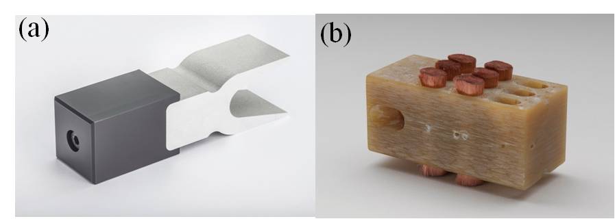
II-B1 C-shaped projectile
II-B2 Brush projectile
This type of projectile consists of six brushes made of many copper fibers ( 40 g) incorporated into a sabot ( 40 g) made of GRP serving as armature (see figure 1(b))[2, 4, 3] leading to a total weight of 80 g as well.
Please note that the difference in weight of the C-shaped and brush armatures is due to material properties. According to [1, 7], the minimum armature mass needed for solid railgun armatures is limited by resistive heating of the metal. This resistive heating is best characterized by the action integral and the action constant , a material property (which is for copper and for aluminum ) [1, 7]. The two are related by:
| (1) |
where is the current carrying cross-section. Using equation (1), we obtain for a minimum armature mass:
| (2) |
where is the railgun bore and the density. For a given action integral and railgun bore the minimum mass armature depends on . That is why, for the same action integral, the mass armature of copper armatures is always higher than the mass of aluminum armatures ( [7]).
II-C Experiments
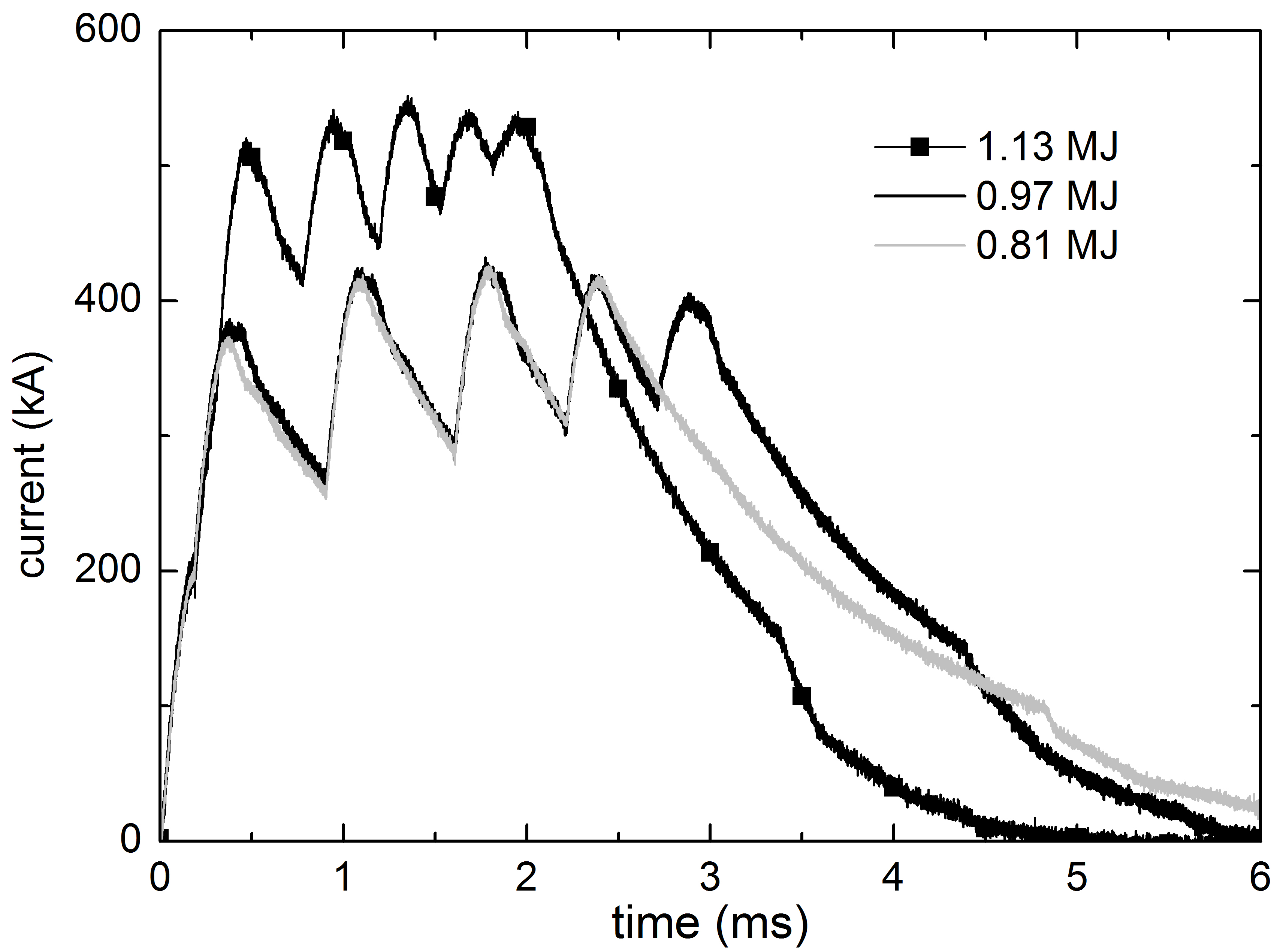
In total we performed a series of 6 single shots. For these shots the applied primary energy was varied from 0.81 MJ to 1.13 MJ in steps of 162 kJ. The applied current pulses used for both types of projectiles are shown in figure 2. Before each shot either new copper (CuCr) rails (for experiments with C-shaped projectiles) or new aluminum (Dural) rails (for experiments with brush projectiles) were mounted into the launcher. In this way the same experimental conditions for each experiment and a good electrical contact between the corresponding projectiles and the rails were assured [8].
III Experimental results and discussion
III-A Muzzle voltage
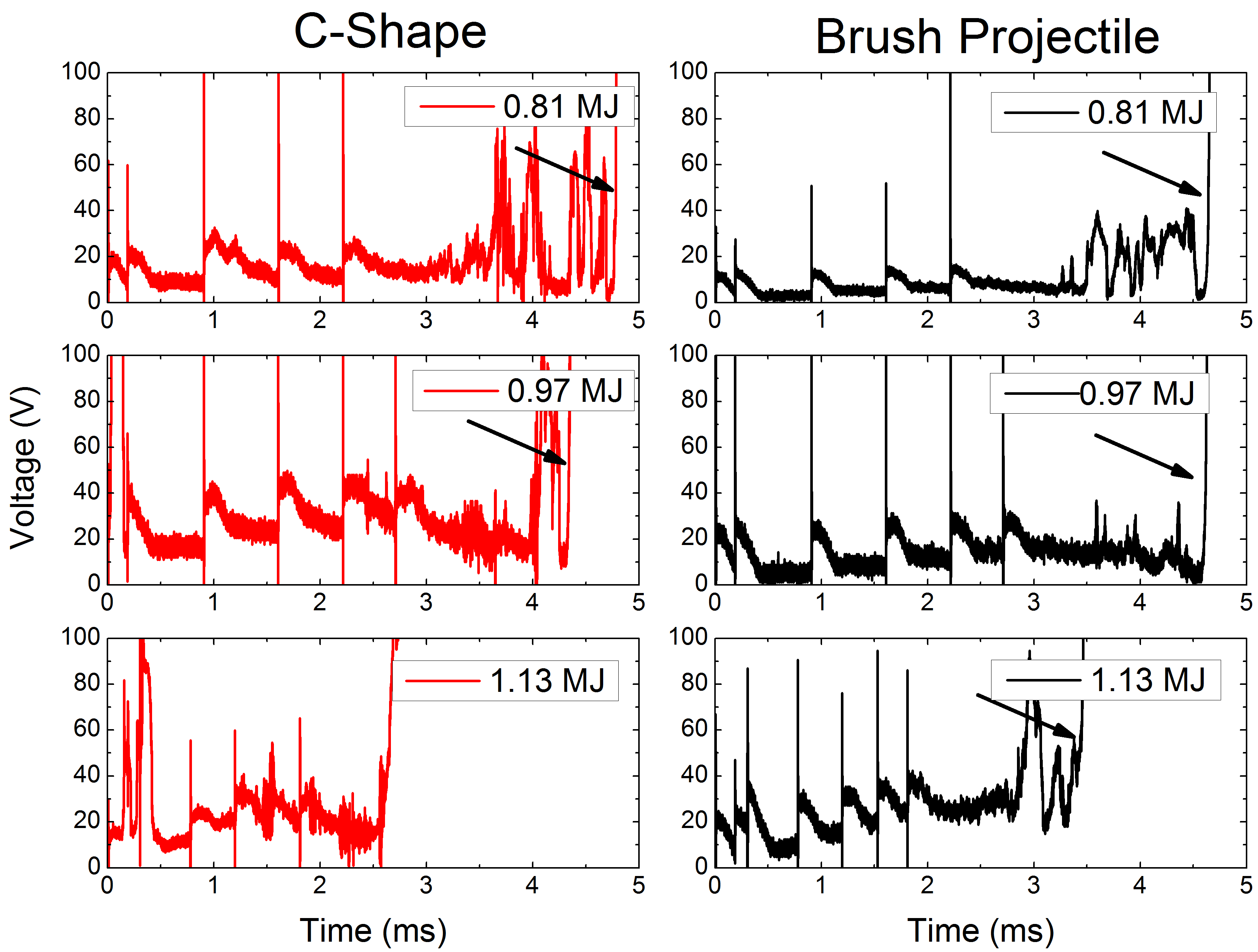
The measured muzzle voltage profiles of all shots are shown in figure 3. The narrow peaks at the beginning of the profiles are due to the discharge of the capacitor units. The number of these peaks corresponds to the number of the discharged capacitor units. The large peak at the end of each voltage profile (U 50 V, see arrows in figure 3) corresponds to the muzzle arc which is formed when the projectiles exits the railgun. In general, a good sliding contact is characterized by voltage amplitudes below 50 V, whereas voltage amplitudes over this value indicate a loss of the solid contact between rails and armature. In case that the solid contact loss leads to an electric arc, the term contact transition is used.
III-A1 Brush projectiles
At the lowest primary energy (E = 0.81 MJ) the average voltage amplitude UM from t = 0 ms until t = 3.5 ms is about 4 V, indicating a good contact behavior. At t = 3.5 ms peaks due to current switching between the different brush armatures appear [2]. These peaks disappear at t = 4.5 ms and the solid contact is re-established before the exit of the projectile at t = 4.7 ms. At E = 0.97 MJ, the voltage profile shows an overall good contact behavior (U 12 V) with only minor peaks due to current switching process between brushes at around t = 3.6 ms. The projectile leaves the launcher at t = 4.6 ms. At the highest primary energy, E = 1.13 MJ, UM is about 20 V between t = 0 ms and t = 3 ms. At t = 3 ms peaks due to the current switching between the different brush armatures start to arise, but no contact transition is observed before the exit of the projectile at t = 3.4 ms.
III-A2 C-shaped projectile
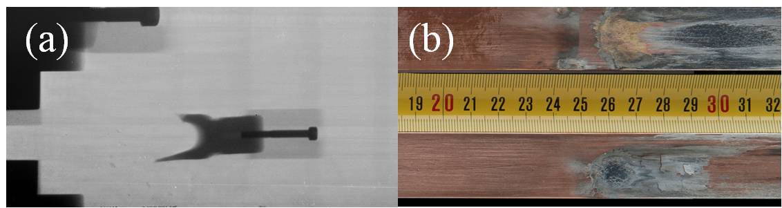
At the lowest primary energy (E = 0.81 MJ) UM is about 10 V between t = 0 ms and t = 3.5 ms. At t = 3.5 ms narrow peaks with amplitudes of up to 80 V appear indicating a temporally loss of the solid contact which is re-established before the exit of the projectile at t = 4.8 ms. These peaks might be attributed to a current switching between local contact zones on the C-shaped armature/rail interface due to material loss and/or the decrease of the in-bore magnetic field, leading to a drop of the compressive force on the armature legs [1]. At E = 0.97 MJ, between t = 0 ms and t = 4.0 ms UM is about 10 V to 30 V indicating a good contact behavior. At 4.0 ms a peak with a width of t = 0.25 ms and a amplitude of U 50 V indicates a temporally contact loss. The solid contact is re-established before the exit of the projectile at t = 4.3 ms. Additionally to this peak a peak at t 0.1 ms appears, which is in correlation with the post-shot state of the rail surfaces (see figure 4(b)) showing traces of molten aluminum on the rails at the start position. Therefore this peak is due to melting of armature material at the beginning of the shot. At the highest primary energy, E = 1.13 MJ, the average muzzle voltage UM is between 10 V and 30 V. At t = 2.6 ms the C-shaped armature undergoes a contact transition, because one of the trailing arms breaks during the experiment (see figure 4(a)). Similar to the primary energy of 0.97 MJ, a peak at around t = 0.2 ms appears as well because of the melting of armature material at the beginning of the shot.
Please note, that UM is always higher for the C-shaped projectile than for the brush projectile. This can be explained by a very simple model: In the case of a C-shaped armature one can assume that the current flows through an area of = 3.4 mm 25 mm = 85 mm2, (3.4 mm is the approximately skin depth of the current and 25 mm is the width of the C-shaped armature) and a length of = 85 mm (corresponding roughly to the circumference of the C-shaped armature). Knowing the electrical resistivity of aluminum () the electrical resistance of the C-shaped armature can be calculated by:
| (3) |
Now using Ohm’s law with I = 400 kA
| (4) |
a muzzle voltage of U 10 V is obtained. In the case of brush armatures is assumed to be 80 mm2 (corresponding to an area of three brushes with a diameter of 5.8 mm) and = 25 mm (corresponding to the caliber size). Using equations (3) and (4) and one obtaines U 2V. In the case of the C-shaped armature the higher muzzle voltage is first of all due to the longer current path in the C-shaped armature ( = 3.4 ) and second due to the higher electrical resistivity of aluminum ( = 1.65 ).
III-B Velocities
Because of the installed Doppler radar system at the muzzle of RAFIRA, the velocity of both types of projectiles for each shot were determined with a very high accuracy[9]. The results of all experiments are summarized in table I. The muzzle velocity increases with applied energy from 955 m/s of up to 1435 m/s for the C-shaped projectile, whereas for the brush projectile the muzzle velocity increases from 1027 m/s up to 1381 m/s. Except for the first experiment the velocity of the C-shaped projectile is always greater () than the muzzle velocity of the brush projectile.
| (m/s) | (m/s) | |||
|---|---|---|---|---|
| Energy (MJ) | C-shape | brush | C-shape | brush |
| 0.81 | 955 | 1027 | 1083 | 1075 |
| 0.97 | 1214 | 1120 | 1207 | 1218 |
| 1.13 | 1435 | 1381 | 1540 | 1501 |
III-C Post shot rail surfaces
The state of the post shot-state of the rail surfaces is an excellent source of information about the sliding contact behavior, because very often state of the post surfaces can be correlated to contact transitions.
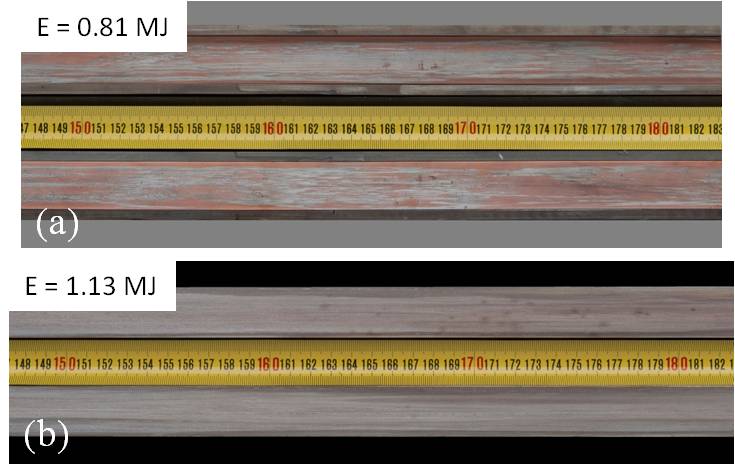
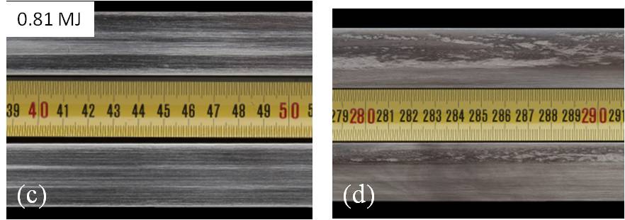
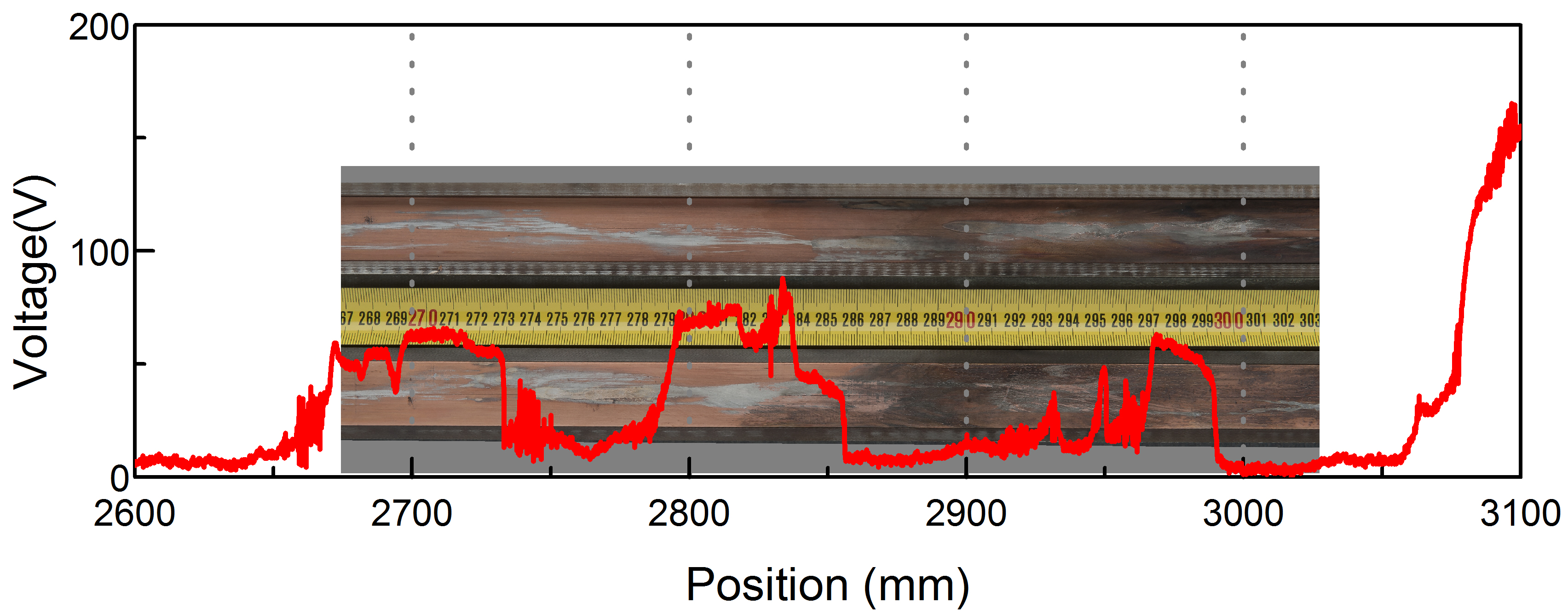
In the case of the C-shaped projectiles the post shot rail surfaces show a more or less uniform layer of aluminum on the rails, whose thickness increases with increasing primary energy (figure 5(a) and (b)). At positions where peaks presumably caused by current switching between local contact zones arise, this layer is no longer uniform anymore but instead shows distinct traces. Additionally, the color of the layer can get darker in that region (figure 6). This fits well to the interpretation that the peaks are caused by current switching between local contact zones.
In the case of the brush projectiles almost no molten copper can be found on the rails. The post shot rail surfaces do only show sliding traces of the brushes before the muzzle voltage peaks occur. At the end of the rails, traces being typical for moving arcs can be seen before the pattern changes due to sliding traces of the brushes back again (see figure 5(c) and (d)) [2, 3].
IV Loss analysis
During a railgun experiment the armature undergoes two main sources of losses: The losses due to friction and the losses due to ohmic heating. Both types of losses will be analyzed quantitatively in this section.
IV-A Frictional losses
The frictional losses of the two types of armatures can be quantified by the energy :
| (5) |
where
| (6) |
is the theoretical (experimental) kinetic energy of the projectile with mass and the corresponding velocity . The values of the experimental velocities are shown in table I. The theoretical velocities are calculated by :
| (7) |
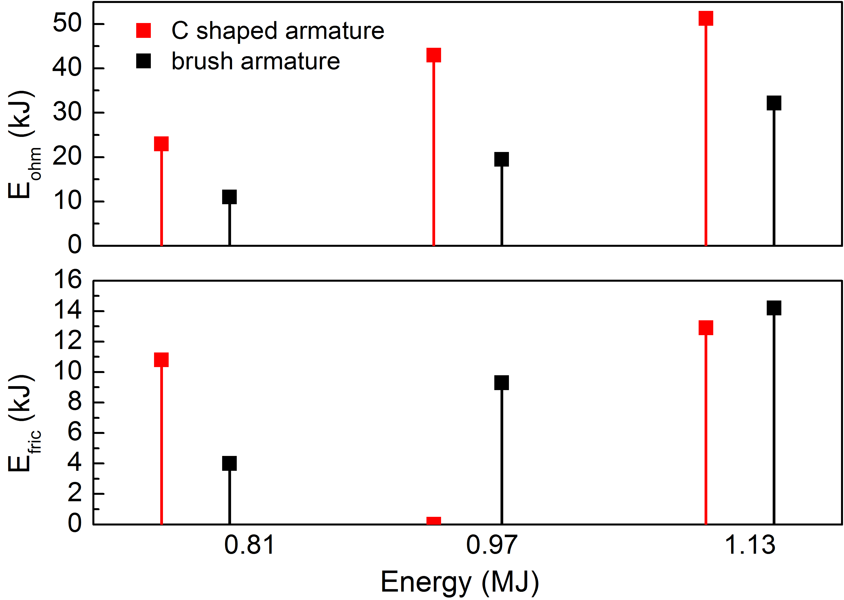
where = 0.45 H/m is the inductance gradient along the rails, and is the action integral, with ms the start time of the shot and the exit time of the projectile of the main launcher. In table I the values of the theoretical velocities (calculated with equation 7) are listed as well. For both equations, (5) and (6) no mass reduction is assumed during the experiment. The results of the calculations are shown as a function of the applied energy in figure 7.
For the lowest applied energy (E = 0.81 MJ), is higher for the C-shaped projectile than for the brush projectile. This might be explained by the fact that the flexible brushes can adapt better to the unevenness of the rail surfaces than the trailing arm of the C-shaped armature [10], although the sliding friction might be lowered by the molten aluminum on the rails.
In the case of an applied energy of E = 0.97 MJ, the dissipated energy due to friction is smaller for the C-shaped armature than for the brush armature. Furthermore, Efric is smaller than in the previous shot. Due to the higher applied energy, more armature material melts during the shot leading to a significant decrease of the friction at the rail/armature interface, which is confirmed by the state of the post shot rail surfaces (figure 5): the layer of molten aluminum on the rails seems much thicker than in the case of E = 0.81 MJ. Furthermore, the very low value of (see figure 7) can only be explained by a significant mass loss of the armature caused by the melting of the aluminum which might have attributed to the higher obtained velocities as well.
In the case of the brush armature, is higher than in the previous experiment. This observation might be explained by an increase of the normal electromagnetic force on the brushes pushing the brushes against the rails [9], leading to a higher friction coefficient. Additionally, copper has a higher action to melt and a higher melting point (action to melt = 80490 A2s/mm4, T = 1083 ∘C) than aluminum (action to melt = 25240 A2s/mm4, T = 660 ∘C) [7], no uniform liquid layer of armature material is formed to lower the friction coefficient as it is in the case of the C-shaped projectile (see figure 5).
For the highest applied energy, is again smaller for the C-shaped armature than for the brush armature, but much higher than in the previous shots. During this shot a part of the trailing arms (see figure 4(b)) was lost during the launch one can assume that both mass and tribological behavior changed, causing a higher . In the case of the brush armature is higher than in the previous experiments, probably due to the same reasons mentioned above.
IV-B Ohmic losses
When electric current flows in a normal conductor, the conductor’s temperature will rise because of the resistive energy loss and/or ohmic losses. In case of the armatures, this energy loss, , is be described by:
| (8) |
where is the resistance of the armature, UM the measured muzzle voltage and the applied current pulse. With the limits of the integral ms and , the integral of equation (8) is calculated for all six shots.
The results of these calculations are shown as a function of the applied energy in figure 7. For each armature type the ohmic losses increase with increasing applied energy, because of the higher applied current. Moreover, the ohmic losses are always greater for the C-shaped armatures than for the brush armatures, which is true for all applied energies. According to paragraph III-A and equations (4) and (3) this can be explained by the longer current path in the C-shaped armature and by the higher electrical resistivity of aluminum.
IV-C Total losses
In order to compare the overall losses of both armatures the total energy loss, , is calculated:
| (9) |
In figure 8 the results of equation (9) are shown for all shots as a function of the applied energy: for both armature technologies the total losses increase with the primary energy, because the ohmic losses and frictional losses, as already mentioned above, increase with the applied energy as well. But the total losses of the brush armatures are about 2/3 of the total losses of the C-shaped technology at maximum, i.e. the smaller ohmic losses of the brushes cannot be compensated by the lower frictional losses of the C-shaped armature. Therefore the total losses of the brush armatures are always smaller than the total losses of the C-shaped armatures, because of the higher ohmic losses of the latter one.
V Efficiency
One important parameter to quantify the performance of the two types of armature technologies is the efficiency, i.e. how the applied electrical energy is converted into kinetic energy. The system efficiency can be defined as:
| (10) |
where Etotal is the initially stored energy in the capacitors and E is the experimental kinetic energy defined in equation (6). With the values of listed in table I, is calculated for each experiment and the results are shown in figure 9. The efficiency increases with velocity for both types of projectiles corresponding to a well-known characteristic of a DC-driven railgun [7]. For the lowest applied energy, is lower for the C-shaped projectile than for the brush projectile (about 10%), because of the lower velocity of the C-shaped projectile. For all other applied energies it is the other way around, because in these experiments the velocities of the C-shaped projectiles where greater than those for the brush projectiles (about 16%).
Another way to define the efficiency is to replace the energy stored in the capacitor by the energy, , delivered to the current injection points, not taking into account any auxiliary systems. We therefore write for this efficiency called :
| (11) |
with the quantity
| (12) |
is the breech voltage defined in [7].
The values of are listed in table II. The efficiency is calculated for all performed shots and the results of these calculations are shown in figure 9. Similar to the quantity , the efficiency increases with velocity for both types of projectiles [7]. Furthermore, is always greater for the C-shaped projectile than for the brush projectile (up to 25 %). According to [7] the breech voltage, and consequently as well, depends amongst other things on the electrical resistivity of the rails. Since we use copper rails in the case of the C-shaped projectile and aluminum rails in case of the brush projectile, is always lower (see table II) for the C-shaped projectiles than for the brush projectiles (up to 25 %). In combination with the experimental velocities, higher values of for the C-shaped projectile than for the brush projectile are thus obtained (see equation (11)). Therefore we can conclude that the projectiles equipped with C-shaped armature converted more efficiently electrical in kinetic energy than the projectiles equipped with brush armatures.
| (kJ) | ||
|---|---|---|
| Energy (MJ) | C-shape | brush |
| 0.81 | 10.3 | 13.7 |
| 0.97 | 16.3 | 16.9 |
| 1.13 | 22.8 | 27.6 |
VI Summary and conclusions
In this paper we performed a series of experiments with projectiles equipped either with C-shaped armatures (made of aluminum) or with brush armatures (made of copper). These projectiles were constructed in such a way, to be as similar as possible in terms of payload and armature mass. But because of the material parameter the mass of copper armatures is always bit than the mass of aluminum for a given action integral. The total mass of both types of projectiles was always 80 g. With the railgun RAFIRA we performed single shots with increasing primary energy (E= 0.81 MJ, 0.97 to 1.13 MJ). The experimental results obtained during the shot were analyzed qualitatively and quantitatively.
Both types of projectiles showed an overall good electrical contact behavior. In the case of the C-shaped projectile a contact transition was observed once at the end of the shot (at E = 1.13 MJ). For both types of projectiles we observed narrow peaks peaks with amplitudes up to 80 V at the end of the shots, indicating a temporary contact loss of the armature. These peaks might be attributed to current switching process either between brushes or local contact zones in case of the C-shaped armature.
In the case of the C-shaped projectiles the post shot rail surfaces showed layers of molten aluminum. In the case of the brush projectiles typical sliding traces of the multiple brushes could be observed on the post shot rail surfaces. For both technologies distinctive traces due to a temporary contact losses could be found on the rail surfaces.
For both types of projectiles we obtained velocities in the range between 950 m/s and 1450 m/s. Except for the lowest applied energy the velocities reached with the C-shaped projectile were always greater than those obtained with brush projectiles ().
The losses due to friction were always, except for the lowest applied energy, lower for the C-shaped armature than for the brush armature. This might be explained by the lower melting point and action to melt of aluminum causing a more or less uniform layer of molten aluminum on the rail lowering the frictional losses. In addition, the caused mass loss of the C-shaped armature due to the melting of the aluminum might have attributed to the higher obtained velocities as well.
In the case of the ohmic losses, the brush armatures showed lower ohmic losses than the C-shaped armatures, because of the lower electrical resistivity of copper and the shorter current path through the brush armature.
Nevertheless, the total losses (sum of ohmic and frictional losses) of the brush armatures amounted to 2/3 of the C-shaped armatures at maximum. Therefore, the smaller ohmic losses of the brushes cannot be compensated by the lower frictional losses of the C-shaped armatures.
Finally, we determined the efficiencies and by comparing the kinetic energy to (the energy initially stored in the capicators) and (the energy delivered to the current injection points), respectively. Both efficiencies increased with increasing primary energy, because of the increasing muzzle velocities. But and are always greater for the projectile with C-shaped armatures than for the projectiles with brush armatures, because of the lower electrical resistivity of the used copper rails used for the projectiles with C-shaped armatures. Consequently, the projectiles with C-shaped armature converted better the electrical energy into kinetic energy than the projectiles with brush armatures.
References
- [1] J. Barber, D. Bauer, K. Jamison, J. Parker, F. Stefani, and A. Zielinski, “A survey of armature transition mechanisms,” IEEE Transactions on Magnetics, vol. 39, no. 1, pp. 47–51, 2003.
- [2] M. Schneider, D. Eckenfels, and F. Hatterer, “Transition in brush armatures,” IEEE Transactions on Magnetics, vol. 39, no. 1, pp. 76–81, Jan 2003.
- [3] M. Schneider and R. Schneider, “Sliding contact performance of multiple brush armatures,” IEEE Transactions on Magnetics, vol. 41, no. 1, pp. 432–436, 2005.
- [4] M. Schneider, R. Schneider, and D. Eckenfels, “Experiments with brush armatures: new technical solutions,” IEEE Transactions on Magnetics, vol. 41, no. 1, pp. 231–234, 2005.
- [5] M. Schneider, M. Woetzel, W. Wenning, and D. Walch, “The ISL Rapid Fire Railgun project RAFIRA part I: Technical aspects and design considerations,” IEEE Transactions on Magnetics, vol. 45, no. 1, pp. 442–447, Jan 2009.
- [6] M. Schneider, M. Woetzel, and W. Wenning, “The ISL Rapid Fire Railgun project RAFIRA part II: First results,” IEEE Transactions on Magnetics, vol. 45, no. 1, pp. 448–452, Jan 2009.
- [7] R. A. Marshall and W. Ying, “Railguns: their science and technology,” China Machine Press, Beijing, China, 2004.
- [8] B. Wild, C. Schuppler, F. Alouahabi, M. Schneider, and R. Hoffman, “The influence of the rail material on the multishot performance of the Rapid Fire Railgun,” IEEE Transactions on Plasma Science, vol. 43, no. 6, pp. 2095–2099, 2015.
- [9] M. Schneider, D. Eckenfels, and S. Nezirevic, “Doppler-radar: a possibility to monitor projectile dynamics in railguns,” Magnetics, IEEE Transactions on, vol. 39, no. 1, pp. 183–187, 2003.
- [10] B. Wild, R. Wenske, D. Simicic, and M. Schneider, “Investigations on the frictional behavior of electromagnetic railgun armatures,” in 2015 IEEE Pulsed Power Conference (PPC), May 2015, pp. 1–5.