FASHION: Fault-Aware Self-Healing Intelligent On-chip Network
Abstract
To avoid packet loss and deadlock scenarios that arise due to faults or power gating in multicore and many-core systems, the network-on-chip needs to possess resilient communication and load-balancing properties. In this work, we introduce the Fashion router, a self-monitoring and self-reconfiguring design that allows for the on-chip network to dynamically adapt to component failures. First, we introduce a distributed intelligence unit, called Self-Awareness Module (SAM), which allows the router to detect permanent component failures and build a network connectivity map. Using local information, SAM adapts to faults, guarantees connectivity and deadlock-free routing inside the maximal connected subgraph and keeps routing tables up-to-date. Next, to reconfigure network links or virtual channels around faulty/power-gated components, we add bidirectional link and unified virtual channel structure features to the Fashion router. This version of the router, named Ex-Fashion, further mitigates the negative system performance impacts, leads to larger maximal connected subgraph and sustains a relatively high degree of fault-tolerance. To support the router, we develop a fault diagnosis and recovery algorithm executed by the Built-In Self-Test, self-monitoring, and self-reconfiguration units at runtime to provide fault-tolerant system functionalities. The Fashion router places no restriction on topology, position or number of faults. It drops 54.355.4% fewer nodes for same number of faults (between 30 and 60 faults) in an 8x8 2D-mesh over other state-of-the-art solutions. It is scalable and efficient. The area overheads are 2.311% and 2.659% when implemented in 8x8 and 16x16 2D-meshes using the TSMC 65nm library at 1.38GHz clock frequency.
1 Introduction
With advances in semiconductor technology, continued scaling and integration of transistors have allowed more system functions to be implemented on chip. The current state-of-the-art in computer architecture design is multicore and many-core systems. A growing number of these systems is being built with 48[1], 64[2], 80[3], 100[4], 256[5] and 4096[6] cores. In these architectures, processing cores are connected together using a variety of fabric interconnect technologies. Network-on-chip (NoC) has emerged as the de facto communication fabric in large multicore and many-core architectures[7][8], primarily due to the lack of scalability associated with bus-based communication infrastructures[9]. The modular structure of NoCs supports more concurrent communications and makes them more flexible for different application communication demands, quality of service (QoS) guarantees and resiliency constraints[10].
As technology scales to the 10-nm regime, the extreme shrinking of transistor feature size and diminishing supply voltage
are making circuits more sensitive to manufacturing process and environmental variations[11][12]. These new semiconductor devices are highly susceptible to early manufacturing defects, and also to latent
defects because of time-dependent degradation and material wear-out, such as oxide breakdown, negative-bias-temperatur-instability (NBTI),
channel-hot-carrier (CHC) and time-dependent-dielectric-
breakdown (TDDB)[13]. Positive-bias-temperature-instability (PBTI) on NMOS has also become more pronounced because the adoption of high-k gate dielectric[14].
The ability of chips to self-monitor and to self-reconfigure in the presence of faults throughout their lifetime is an important design paradigm going forward[15]. Dynamic hardware-supported fault-detection algorithms are being implemented [16]. Systems, where architecture states and systems parameters are periodically copied and stored to allow rollbacks with built-in restoration mechanisms, have been proposed[17]. Beyond hardware solutions, software approaches that can be used to complement hardware functions and further mitigate fault-induced system performance impacts have also been suggested[18][19][20][8].
Unfortunately, the Network-on-Chip (NoC) layer of the architecture is not immune to these effects. In fact, since the NoC provides connectivity between the various components of the system, fault-tolerance has become an essential feature that must be brought to the forefront of the NoC design. It is important to maximize the on-chip resource utilization throughout the lifetime of multicore and manycore systems when the reduction of component reliability is unavoidable. Router microarchitectures and routing techniques that are more resilient to component failures and guarantee a higher degree of node connectivity have started being investigated[21, 22, 23]. Router/link faults in NoCs change the underlying topology. This introduces three key challenge for fault-tolerance: (1) Deadlocks: The disconnection of certain routers and links can lead to cyclic dependencies between network resources, leading to a network deadlock. To avoid deadlocks, cyclic dependencies in the channel dependency graph of each new topology need to be removed. (2) Performance: Faults lead to a loss of path diversity in the NoC, and higher congestion for certain paths. Adaptive routing[24][25] can mitigate some of these effects, but have to remove certain channel dependencies or prohibit certain routing paths, which reduces routing path diversity even further[26]. (3) Scalability: As we add more cores in a system, the size of the NoC grows and warrants a distributed solution since centralized solutions are not going to scale.
The key contribution of this work is a holistic and scalable NoC reliability solution called Fault-Aware Self-Healing Intelligent On-chip Network (FASHION) that address all three challenges listed above. We introduce a distributed intelligence unit called Self-Awareness Module (SAM), that allows the router to (1) automatically detect permanent component failures and generate a network connectivity graph through a distributed spanning tree search algorithm with computational complexity of , where is the link number in the network, (2) implement in-hardware self-adjusting techniques to guarantee connected and deadlock-free routes inside the maximal connected subgraph with computational complexity of , where is the number of nodes in a network, and (3) support the adoption of bidirectional links and unified virtual channel structure to further strengthen the network connectivity and sustain a relatively high degree of fault-tolerance. This work merges these concepts together to provide a robust and practical solution for mitigating fault-related system performance degradation.
FASHION can also be extended to the NoC power gating domain where links and routers are power-gated to reduce NoC static power dissipation. Several previous works [27, 28, 29] have come up with innovative power-gating techniques to selectively power-gate low utilization NoC components while providing minimal disruption to the NoC traffic. Power-gating of links and routers, however, creates deadlock-prone irregular topologies that change dynamically, thereby introducing the same performance and deadlock challenges listed earlier. This work proposes a new re-configuration algorithm that provides deadlock-free paths in an arbitrary irregular topology and can thus be leveraged by existing works in NoC power-gating domain to further strengthen their schemes.
The rest of the paper is organized as follows. Section 2 highlights the related works. The effects of faults on network connectivity in NoC-based architecture are introduced in Section 3. Router micro-architecture details are presented in Section 4. Section 5 describes the Fashion fault detection and reconfiguration algorithm. Section 6 presents the extended Fashion architecture. Evaluations and discussions are presented in Section 7. Finally, Section 8 concludes the paper.
2 Related Work
Modern computer architectures already implement a variety of mechanisms to improve system reliability. Existing approaches for NoC resilience are either on-line or off-line. Off-line reconfiguration algorithms[30][31][32] use knowledge of the underlying network topology to compute routing decisions. On-line solutions are implemented in hardware under a tight area and power budget and can leverage the on-chip resources to run both detection and recovery programs. On-line solutions are more attractive than off-line solutions, because they generally consume fewer resources and have better scalability and computational efficiency. The Fashion architecture uses an on-line fault-tolerance approach.
A large number of fault-tolerant routing algorithms have also been proposed. Immunet[33] is able to tolerate any combination of faults as long as the network is connected. Fick et al. introduced a low overhead routing algorithm named Vicis[34], Gomez et al. provided an intermediate node based fault-tolerant routing by using escape virtual channels in each phase[30], Ariadne[35] leveraged Up*/Down* routing[36], which assigned each link either “up” or “down” direction and disallowed transmission from “down” to “up” to break cyclic dependencies. A distributed and lightweight fault-tolerant routing algorithm, named Hermes[37] was proposed by Iordanou et al.. It applies XY- or O1TURN-routing for high throughput, while choses the Up*/Down* routing rule to ensure acyclic path formations to avoid deadlock and achieve fault-tolerance.
Sylvester et al.[19] claimed that an on-line self-organization mechanism is crucially important to improve the effective yield throughout the lifetime of SoCs. The ForEVeR algorithm[38], applies formal methods and runtime verification to ensure functional correctness in NoCs. Murali et al. demonstrate that hybrid error detection and correction mechanisms provide better performance[39]. A recovery mechanism named drain was introduced in[20] to provide system-level recovery for any number of disconnected nodes caused by permanent failures by sending the architectural state and dirty cached data from disconnected nodes to healthy caches nearby to reduce the effects of failures.
Other architecture level improvements for NoC reliability have been studied. Kim et al. proposed a row-column decoupled router[40], which employed decoupled parallel arbiters and small crossbars. Palesi et al. introduced a scheme to efficiently use partially-faulty links[41]. NoCAlert[42] is an on-line and real-time fault detection mechanism which operates seamlessly and concurrently with normal NoC operation.
Recently, Parikh et al. proposed a fine-resolution detection and reconfiguration strategy to cope with permanent faults, named uDIREC in[23]. Similar to prior work by Shamshiri et al.[43], uDIREC uses a “supervisor” node to make detection decisions and stores the topology information in a software-maintained scoreboard at that node. It then applies Up*/Down* routing[36] to guarantee deadlock avoidance. In Up*/Down* routing, all links are tagged as Up or Down relative to a root node, and a message is not allowed to make Down to Up turns. In order to maximize network connectivity, uDIREC needs to implement the breath-first search in software and discover the optimal solution via an exhaustive search of the “root” node. We find that the Up*/Down* routing scheme disables a large percentage of turns to break cycles which lower routing options and sacrifice network performance, because there are only two type of turns (“up-to-down” and ”down-to-up”). In contrast, compared with uDIREC, Fashion only need to be executed once to detect the connectivity of the underlying network. Also, our experimental results show that the Fashion architecture is more efficient in terms of computation complexity, scalability and the degree of fault tolerance. According to our experiments (see Section 7), the average percentage of forbidden turns of Fashion is 14.1% less than Up*/Down* routing.
In the NoC power-gating domain, NorD [27] a recent work, uses a high-latency ring snaking through the network as the escape path. Packets are routed adaptively till their mis-routed hop-count increases beyond a certain threshold upon which they are forced to enter the escape path. Router-parking [28] replaces the high latency ring of NorD with an escape-path constructed using up-down routing. Deadlocks in this scheme are detected using counters and one Virtual Channel per Virtual Network per Input port is always kept reserved for the escape path. Panthre [29] does away with the escape-path and instead uses Up*/Down* routing for all the VCs. However, as pointed out earlier, Up*/Down* routing provides deadlock-freedom at the cost of significant reduction in path diversity. In addition, certain traffic flows are forced to use non-minimal paths leading to increased latency and energy consumption. In contrast, FASHION provides 4.80%, 6.06% and 14.67% lower latency to traffic on average compared to up-down routing at 5, 10 and 15 power-gated links respectively. Moreover, it provides low re-configuration time which is very useful to schemes in NoC power-gating domain as power-gating decisions are taken every epoch (usually 10K cycles), thus requiring the network to be re-configured every epoch if there is a change in the active topology.
3 Effects of Faults on Network Connectivity in NoC-based Architectures
For the communication infrastructure to dynamically identify components with permanent or transient faults and to autonomously self-reconfigure, the network router needs to exhibit some inner intelligence. To describe the Fashion architecture and its functionality, we begin by giving the standard definitions for network channel graphs and cut-elements.
Definition 1
Given a network-on-chip characterization graph , where the routers and links in the network are given by the sets and , represents the router associated with processor element , while each arc represents a link from to . For a given , two vertices and are called connected elements if contains a path from to ; graph is said to be connected if every pair of vertices in is connected; A cut vertex of is a vertex whose removal results in a disconnected ; A cut edge of is an arc, whose removal disconnects . Together cut vertices and cut edges form cut elements and are critical to the connectivity of .
Definition 2
A rooted acyclic graph is a graph in which one of the vertices is distinguished from the others. This particular vertex is called the root of the graph. In a rooted graph with root , any node on the unique path from to a node is called an ancestor of , and is called a descendant of . If the last edge on the path from the root of the graph to a node is , the is the parent of , and is called a child of , denoted and . If two nodes have the same parent, they are siblings; a node with no children is a leaf.
As stated in the Definition 1, a cut-element is an element whose removal breaks network connectivity and an element may be a vertex or an edge. The connectivity of a network graph dictates path diversity and routing choices in the NoC. Node pairs can only communicate if they belong to the same connected subgraph. The vertex set contains all the connected subgraph of , the maximal connected subgraph is the one with the maximal number of vertices. The is completely determined by the topology of the G.
uDIREC[23] performed a study where stuck-at faults were injected in a 5-ports wormhole router, in a spatial distribution proportional to the silicon area of gates and wires. Their analysis revealed that 96% of faults affect only a small fraction of the router logic. Furthermore, the effects of these faults can be entirely masked by disabling and re-routing around a single router link (e.g. error in the input buffer). The other 4% of faults can cause the entire router to fail. These faults often involve the router’s control logic or critical components like the arbiter or crossbar. Therefore, in the simulation results presented in this paper, we assume a uniform-random distribution of faults with the ratio of faulty links to faulty nodes as 24:1.
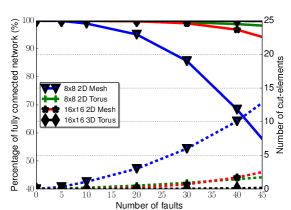
Fig 1 shows the connectivity impacts of different percentages of faulty components/routers for different sized networks. Unpredictable faults may occur at any place in the network, thus we assume a uniform-random distribution of faults over silicon area. The results presented are the average outcome from 100,000 simulations for each case using the hornet[44] simulator. For a medium sized 64-node 2D-Mesh network, there are roughly 6 cut elements out of 30 faults. This corresponds approximately to 14.73% of network connectivity loss. Fig 1 highlights the relationship between average number of cut elements and the percentage of fully connected network. Notice that the maximal connected subgraph () normally forms an irregular graph, which cannot guarantee all the node-pairs in the are able to communicate with each other, because the practical connectivity is determined both by the topology of as well as the routing algorithms[45]. We will show that Fashion ensures connectivity inside the in Section 5.3.
Network connectivity decreases at a faster rate with an increasing number of faults. The need to maximize on-chip resource utilization becomes accentuated with decreasing network component reliability. Hence, (1) determining whether defective components are cut elements of the network and identifying connected subgraphs of a disconnected NoC and (2) mitigating their negative impact on network performance by reconfiguring the NoC and maintaining network connectivity are at the core of Fashion’s fault-tolerance scheme. ‘
4 Fashion Router Architecture
4.1 Micro-Architecture of Self-Awareness Module
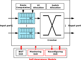
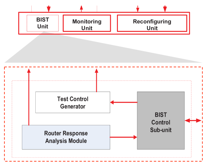
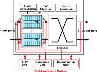
In conventional wormhole virtual-channel routers[46], the routing operation generally takes four steps; namely, routing (RC), virtual-channel allocation (VA), switch allocation (SA), and switch traversal (ST), where each phase corresponds to a pipeline stage in the router. In Fashion, the architecture is augmented to support runtime self-monitoring and self-reconfiguration. Figure 2 depicts the Fashion architecture. The key architectural modification is the introduction of the Self-Awareness Module (SAM). The module contains a Built-In Self-Test (BIST) unit, a Self-Monitoring unit and a Self-Reconfiguration unit. Network SAMs also generate network probing traffic. SAM is out of the critical path of the NoC router, each unit is active only during its specific working period and disabled with power-gating in other cases to reduce power and wear-out faults.
4.2 Self-Monitoring unit
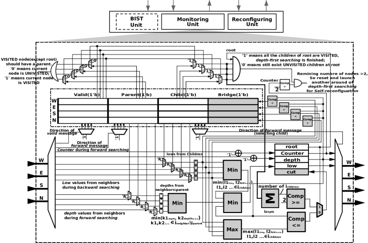
The Self-Monitoring module monitors and captures on-chip network events. It has an embedded neighbor list table used to record the states of its immediate neighbors and its relationship with them. Each entry in the table corresponds to a port, for a 2D-Mesh/Torus network, there are four entries in the table. The entry is set to “1” if the link connecting the port to a neighbor is detected as a cut edge, cf., lemma 2 in section 5.2. The entry indicates whether or not a neighbor exists or is temporally out-of-service (e.g. due to power-gating) or permanently removed from the network. Figure 3 shows the Self-Monitoring micro-architecture.
The Self-Monitoring module initiates periodic runs of the BIST module by built-in timer. It can also be launched by OS to obtain connectivity information before assigning new applications (or threads) to available processing elements. When the BIST unit detects a fault, the Self-Monitoring unit is responsible for determining the criticality of the affected component in the network. It does this by building a network connectivity map and labeling all of the cut-elements through a fully distributed depth-first search algorithm. The details of the algorithm are presented in Section 5.2. It has a one-bit status register named used to label a given router component as a cut-vertex or not, a built-in combinational circuit to determine values, cf., lemma 2 in section 5.2, and a one-bit status register, assigned at the beginning of the depth-first search, to indicate whether or not the component is . The Self-Monitoring’s responsibility is to monitor network activities and to record fault induced topology changes and network connectivity. It is also responsible for sending and forwarding potential lost packet messages to neighboring routers for retransmission after self-healing reconfiguration.
4.3 Self-Reconfiguring unit
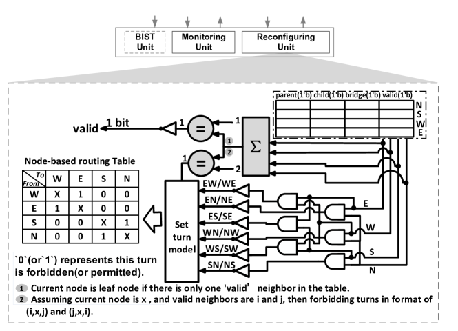
The Self-Reconfiguring block shares the Self-Awareness Module’s neighbor list table with Self-Monitoring unit and updates it with prohibited routing turns based on the new network connectivity graph constructed by the Self-Monitoring unit. Figure 4 depicts the functional view of Self-Reconfiguring unit.
The number of valid neighbors in the table represents the degree of the current node, a node can be detected with no propagating effects if the number of valid neighbors is 1. Routing algorithms, both source routing and node-table routing, forbid turns to prevent deadlock[47][48]. In the Fashion architecture node-table routing is adopted because it is more amenable to the distributed decision structure in the architecture. The lower half of Figure 4 represents an extension of routing table information; it stores the outgoing ports a packet should take to reach the next downstream node. If West-to-South turn is faulty, or disabled for deadlock-freedom purposes at the current node, then the table entry is set to “0” to indicate that it is not allowed with ‘W’ and ‘S’ as horizontal and vertical indexes. The table entry is set to “1” when the turn is permitted. The comparator circuits are used to test the number of valid neighbors to a given node in the network.
In general, node-table based routing may lack scalability. However, the node-table inside the Self-Monitoring unit is designed to store information about permitted (or forbidden) turns at the router. This approach is different from the conventional node-table based routing, where the router generally contains routing information for all the flows that pass through it. Therefore, our node-table size remains constant for the same topology, even with different network sizes.
When a new permanent fault is detected by the Self-Monitoring unit and it must be reflected in a modified topology. The Self-Reconfiguring unit will be triggered when the newly discovered fault is identified as a cut-element. The details of the algorithm are introduced in Section 5.3.
4.4 Built-In Self-Test unit
The embedded Built-In Self-Test (BIST) unit is very standard. It sends test signatures to its neighbors and compares received signatures from different directions. If for a given period of time, the BIST unit receives no signature response from a neighbor or notices that the received acknowledges are different, then it labels the node as disconnected and sets the “valid” bit of the corresponding neighbor list table entry to “0”. Having a BIST block located in each router not only decouples the processor element testing from the router[49][43], but it also allows the unit to be used by Self-Monitoring unit to probe links and router internals status. Figure 5 shows the BIST unit in the Fashion architecture.
The BIST unit can also be used in the NoC power-gating domain. A neighbor that is power-gated will be unresponsive and act like a transient fault. The remaining steps of the Fashion design remain the same. When the neighbor is turned on again, it will be added back to the connected sub-graph and the reconfiguration algorithm run again. Thus, without loss of generality, we present our analysis assuming unresponsive elements are due to faults.
5 Fashion Fault Detection and Reconfiguration Algorithm
In this section, we present the fault diagnosis and recovery algorithm executed by the Built-In Self-Test, Self-Monitoring, and Self-Reconfiguration units. The root of the graph corresponds to the System Manager and is always active. The algorithm starts and terminates at the root node. The root node is selected in a manner that maximizes its degree. The average degree of a graph G is and , where and are the minimum degree and maximum degree of the Graph. This selection method improves the root node’s aliveness and connectivity probabilities.
5.1 Fault Detection and Classification Algorithm
The Self-Monitoring unit periodically executes the BIST unit. When a new failed component is detected. The Self-Monitoring needs to verify whether the underlying network is still connected. Tarjan[50] introduced a central cut vertex detection scheme using depth-first search. However, Tarjan’s approach is not able to detect cut edges and is not suitable to directly implement in a distributed system such as a NoC. The Fashion detection algorithm works in a distributed mode and simultaneously detects both cut vertices and cut-edges for dynamically changing network topologies. The algorithm is executed at network SAMs layer.
5.2 Self-Monitoring Algorithm
The Self-Monitoring procedure has two phases:
-
1.
Construct the depth first tree: During the depth-first traversal the positions and relationships of network nodes and links are recorded;
-
2.
Identify the cut elements and connected subgraphs: Nodes and edges are identified and labeled whether they are cut vertices and cut edges according to their location established during the search.
For a node , is the distance from the node to root; is the minimal value among the node, its non-parent neighbors and the minimal value of its children:
Where, , and .
Construction of the depth first tree: This procedure is initiated and terminated at both the root node. The counter records number of connected components after the execution. Each node is either unvisited or visited during the process. Already explored nodes are marked as a child of previous visited node, in other words, there is one and only one parent entry in the neighbor list table set to at a visited node. Thus the parent entry state implicitly indicates whether the current node is visited or not.
At the beginning, all the vertices of the network are unvisited and all the variables are initialized (noted as , , , , , and contains the node ids of all its one-hop neighbors, the latter three pieces of information are stored in neighbor list table, is the number of total nodes). From the hypervisor or the system manager, the operating system launches the construction of depth first tree.
The source vertex is marked as the root (), then is also updated () and the is set to . Vertex executes forward search to explore unvisited nodes as “deep” as possible, sends a forward message to one of its unvisited neighbor in the neighbor list table and marks as ’s child () and passes and to . At node , is marked as ’s parent () and the update is performed. The variable is also incremented by one ().
The exploration of unvisited neighbors at is then launched. When does not have any unvisited neighbors, it executes the backward search to discover unvisited neighbors of (). It updates values of all the nodes along the backward paths. Figure 3 shows the “neighbor-to-neighbor” communication infrastructure and how recording and updating of all the necessary informations are done during the depth first tree searching.
During the backward search, sends a backward message to (). If vertex is the root and all of its children are already explored, then the depth-first search algorithm has walked through all the vertices belonging to the depth first tree. If is a non-root vertex and there are no unvisited nodes inside , the algorithm moves up to ’s parent and is updated according to formula (1). The value is passed to and depth-first search at continues until all the vertices are visited. The connected subgraph initialized from the hypervisor represents the maximal connected subgraph, also called the connectivity map of network. The other unvisited nodes are disconnected from the system manager and are labeled as out-of-service, since they cannot be reached or used. The gray components in Figure 3 show the backward search logic, including the comparison operation in formula (1) and the setting of the cut-bit. In Section 6, we further demonstrate how the connectivity of the network can be improved by leveraging the bidirectional links and unified virtual channels.
Criterions to identify cut elements Assuming is the depth-first forest of , then the following two rules are used to classify the system nodes as cut or non-cut elements[51]. A back edge is an edge that directly connects a node to its ancestor, and there also exists another path from its ancestor to the node itself through tree edges.
-
•
lemma 1. Cut vertex detection: For a vertex , if (number of , or , ;
-
•
lemma 2. Cut edge detection: For an edge , where , = if and only if is a tree edge.
Proof of lemma 1 (cut-vertex detection): The first part of lemma 1 is obvious, if is root and it has multiple children, it is the cut-vertex and vice versa.
Let us consider the case where is a non-root cut vertex. There and there is no back edge from or any of to a proper of . Thus, ¡ and is less than the value of any neighbor of . If Ø and , then there is no back edge from to any of since is also a of . It follows that . Otherwise, if Ø, will be a leaf node and .
The proof of the converse, goes as follows: according to the definition of , (a) , (b) , , and (c) , . Statements (b) and (c) guarantee that no back edge from () or any descendant of to a proper ancestor of .
Proof of lemma 2 (cut edge detection): If edge is a cut edge, then ¡. According to the property of cut edge, does not lie on any cycle, thus there is no edge from and to . Therefore, ¿.
To prove the converse, let us assume that is the tree edge and ¡ , then according to formula (1), we have:
(a) ¿, because ; (b) ¿
, , there is no back edge from to of ; (c) ¿, , there is also no path connecting to without passing through node . As a result, did not form a cycle and the converse part of the lemma 2 is true.
5.3 Self-Reconfiguring Algorithm
This part of the algorithm is designed to remove deadlock and preserve the connectivity inside the . Here, we construct an acyclic channel dependency graph (ACDG) that breaks all cycles to avoid in-flight packets becoming trapped in a cyclic pattern, while preserving connectivity by prohibiting turns only at non-cut elements. The procedure consists of:
-
1.
Identifying the leaf nodes set in the . Every connected node can independently determine whether or not it is a leaf node by checking whether the child entry in its neighbor list table, see Figure 4;
-
2.
Identifying the non-cut vertices set in the with minimal degree (for example, the minimal degree is 2 for 2D-mesh/torus network). This can also be achieved individually by counting the number of connected neighbors in the neighbor list table. Then, we can forbid turns in the form of and at node , () and . Prohibited turns appear in pairs and are recorded in the node-based routing table, see Figure 4;
-
3.
Removing and from by updating the valid-bit to for all their connected neighbors. Since all the removed nodes are non-cut vertices, deleting them does not affect the connectivity of the rest of nodes in ;
-
4.
Constructing a new by running another round of spanning tree search. After that, repeat these procedures until the remaining vertices number of is equal to 2 (). Notice that, removing non-cut elements does not affect the connectivity of rest nodes in the . The modification of the topology of will however change the cut vertex set and degrees of nodes. Therefore, another around of spanning tree search executed by Self-Monitoring Unit is needed;
Strictly forbidding turns only at non-cut elements position will not destroy the connectivity of the network. The proof for the deadlock-freedom property of the proposed Self-Reconfiguring algorithm is done by reductio ad absurdum:
It is well known that a routing algorithm is deadlock-free if the nodes can be numbered and messages can only traverse nodes in a strictly decreasing (or increasing) order. So, assuming that the removed nodes in the same iteration have a unique label, and this label is increased at the beginning of next iteration. Every node will have a label when the algorithm is finished. If there is a cycle in the network, and node is with the minimum in . Then, there exists a turn in cycle , both and are greater than .
However, according to the second procedure in the Self-Reconfiguring Algorithm, turn is prohibited, , which brings a contradiction. Therefore, cycle is non-existent. In this way, we guarantee that the self-reconfiguration procedure supplies a deadlock-free and connectivity guaranteed routing solution inside the maximal connected graph. This property has also been proved by our experiments.
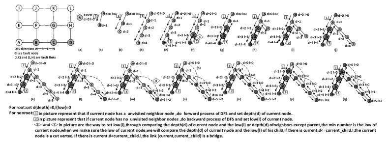
5.4 Illustrative case of the classification procedure
In this illustrative case, we consider a network consisting of nodes. There are associated with each node, see Figure 6. Fault links and are marked with dashed lines. Cut elements and cut edges are shaded. The classification routine takes 22 steps to complete. At the beginning, is selected as the root followed by a visit to node and the update , shown Figure 6(b). The search continues until it reaches , where there is no unvisited neighbor. A backward search is then initiated with the appropriate updates and ( is ) - Figure 6(e). In Figure 6(g), the backward search reaches node and discovers node not yet visited.
A new forward search starts and the update is made. The forward search reaches node , where a back edge connects and , and is set equal to - Figure 6(k). The next step is a backward move to update - Figure 6(l). At node , the algorithm discovers that edge connects to the , and the result is according to formula (1), shown in Figure 6(m). The depth first tree rooted at has 9 vertices - Figure 6(p), which forms the maximal connected subgraph. There are still unvisited (disconnected) nodes and in the network, which are labeled as out-of-service.
5.5 Algorithm complexity analysis
In the algorithm, each edge in the network is traversed at most twice in the building of the depth first tree. The upper bound of the algorithm is therefore steps, where is the number of edges in the network. The part of the algorithm that executes on the Self-Monitoring unit needs time to finish. In the Self-Reconfiguring unit, every node is checked to determine leaf nodes. Prohibiting turns may prompt re-runs of this part of the algorithm. Therefore, the Fashion algorithm has worst-case computational cost of . For a 2D-mesh network, , , and the computational complexity is . In the conducted experiments, it took an average of 706.49 and 1384.45 clock cycles to finish the scheme on networks of 64 and 256 nodes.
5.6 System deployment senario
Researchers have realized that addressing the challenges of permanent errors in NoC requires combining both hardware and software efforts. While hardware is required to recover from permanent defects and self-adjust to continually guarantee correct operation, the software is responsible for eliminating the fault-induced performance impacts[18][19][20][8].
At runtime some information may be exchanged between the operating system (OS) and the Self-Awareness Module (SAM). However, the proposed algorithm is executed entirely by the SAM unit. The OS can trigger and interrupt the execution of the algorithm. For example, the OS can periodically activate the BIST or Self-monitoring units to obtain connectivity information before assigning new applications (or threads) to available processing elements. The monitoring, reconfiguration and built-in testing sub-units are programmed before the start of the application execution alongside the routing tables and virtual channel allocation algorithms.
During the application execution, the SAM unit is activated periodically, meanwhile, architecture states and other parameters are periodically in memory. When a fault is detected, packets and flits are stalled at their destinations. Using functional links, potential lost or corrupted packet messages are sent back to neighbors and propagated from there depending on the criticality of the fault. The SAM unit then goes through its local self-healing/reconfiguration process. When it is done, credits are updated and normal application traffic can resume going through the router. The restoring mechanism rolls back to a previous error-free execution point, and the system moves forward to the next state.
In general, the software stack is oblivious to the online detection and reconfiguration. The system software may be involved if substantial part of the chip becomes faulty, necessitating a full system pause and global reconfiguration e.g., a time-out mechanism for dropping on-the-flight packets and issuing retransmission[39].
6 Extended-Fashion Router
To give the network flexibility and adaptation range, two key ingredients are added to the Fashion router design, namely, coarse-grained reconfigurable bidirectional physical links and unified virtual channel structure, as shown in Figure 7.
Cho et al. [52] introduced a bandwidth-adaptive network where the link bisection bandwidth can adapt to changing network conditions using local state information. Similar work using bidirectional links is proposed in[53]. In these schemes, unidirectional links between network node pairs are merged into a set of bidirectional links. Each new bidirectional link can be configured to deliver packets in either direction. The links can be driven from two different sources, with local arbitration logic and tristate buffers ensuring that both do not simultaneously drive the same wire. Tsai et al. [54] successfully used this approach to handle static and dynamic channel failures on the data-link layer. The Ex-Fashion architecture extends the concept by using the bidirectional nature of links to sustain higher connectivity and rebalance link bandwidths around faults in a coarse-grained fashion. The robustness of this approach is drawn from the fact that component failures affecting one datapath-segment account for 96% of faults and can be entirely masked by rerouting around a single link[23].
Virtual channels are another point of vulnerability that is highly susceptible to faults[22]. Instead of having a set of virtual channels strictly associated to a given port as seen in the conventional router, Ex-Fashion has a pool of virtual channels that can be shared among the ports. It follows the unified virtual channel structure approach of the ViChaR[55] router architecture. In this framework, virtual channels are not statically partitioned and fixed to input ports, they are rather communal resources dynamically managed by the SAM unit. This approach allows for faulty buffer to not impact any particular port or render a port unusable. In ViChaR, the authors showed that the area and power overheads are negligible and network latency can be decreased by 25% on average using a unified buffer structure scheme.
In Ex-Fashion, the overheads are even lower, because the virtual channel depth is kept constant removing some of the complexity associated with the ViChaR architecture. Although the use of bidirectional link and unified virtual channel structure are not new, their combination and the design of distributed intelligence, i.e., Self-Awareness Module (SAM) to dynamically manage them, represents one of major contributions of this work. The implementation of bidirectional link could improve the connectivity of the network, therefore achieving a better network connectivity map during the self-monitoring phase.
For example in the network shown in Figure 6, if the link from node to is broken but the link from to is still functional, using the time-division-multiplexed property of the bidirectional link in the Ex-Fashion router architecture, we perform direct packet routing between nodes and . And the maximal connected graph would contain two more nodes than Fashion architecture.
Furthermore, a single broken input buffer at a port would not affect the correct functionality of the input port using the unified virtual channel structure, which will further improve the fault-tolerance of the architecture. The possibility of disconnected node is significantly reduced in the new extended router architecture. The Self-Reconfiguring module in the Ex-Fashion reconfigures the physical links and recomposes the unified virtual channel structure to match the new link directions.
7 Evaluation
| Fault | 8x8 2D mesh | 16x16 2D mesh | ||||||
|---|---|---|---|---|---|---|---|---|
| Fashion | Ex-Fashion | Fashion | Ex-Fashion | |||||
| num | Avg.cut-e | Fully Connected | Avg.cut-e | Fully Connected | Avg.cut-e | Fully Connected | Avg.cut-e | Fully Connected |
| 10 | 1.064 | 99.03% | 0.057 | 99.99% | 0.015 | 100% | 0.014 | 100% |
| 20 | 3.014 | 95.13% | 0.142 | 99.99% | 0.191 | 99.83% | 0.035 | 100% |
| 30 | 5.996 | 85.67% | 0.247 | 99.94% | 0.693 | 99.11% | 0.041 | 100% |
| 40 | 10.075 | 68.39% | 0.386 | 99.82% | 1.714 | 96.83% | 0.060 | 100% |
| 50 | 15.517 | 47.46% | 0.554 | 99.70% | 3.303 | 91.69% | 0.079 | 100% |
| 60 | 22.608 | 26.34% | 0.781 | 99.40% | 5.553 | 82.05% | 0.096 | 99.96% |
In this section, we provide extensive performance evaluations of the Fashion and Ex-Fashion architectures.
7.1 Hardware Complexity Evaluation
To accurately evaluate the hardware complexity of the Fashion architecture, we use the Synopsys Design Complier with TSMC 65nm standard cell library to estimate the architecture area overhead. The amounts of hardware required to implement the self-monitoring unit and the self-configuring unit are and , respectively. The area is for a 64-bit router of an 8x8 2D-mesh, with four virtual channels at each port, and each virtual channel is eight flits depth. Thus, the area overhead of self-monitoring and self-configuring units are 0.966% and 1.345%, respectively. As for a 16x16 256 2D-mesh, the area percentages are 1.139% and 1.521%, respectively. Total area overheads become 2.311% and 2.659% for Ex-Fashion router on 8x8 and 16x16 2D-meshes when the unified virtual channel structure and tristate controller added to the physical links are factored in to the logic cost.
7.2 Simulation Details
We used hornet, a cycle-level many-core simulator[44] for our simulations. We implemented 8x8 2D-meshes with different numbers of faults. Unpredictable faults may occur at any place in the network, thus we assumed a uniform-random distribution of faults over silicon area. As previously mentioned, 96% of the faults can be masked as broken links[23] and others are diagnosed as fully broken. For the experiments, the ratio of fault links and fault routers is around 24:1, as described in Section 3. 100,000 simulations are performed with various fault numbers and distribution for synthetic benchmarks to explore as many different fault combinations as possible. Applications are reconfigured to run on the maximal connected subgraph if the network becomes disjointed due to faults. All experiments have 200,000 warm up cycles and a total of 1,200,000 analyzed cycles.
7.3 Connectivity Analysis
Table I yields important insight into the large scale system and proposed Fashion. There is a high probability that the network will be split into disjointed subgraphs when the number of faults increase, and the system size makes acquiring a global defect map impractical as the number of nodes increases. An on-line and distributed light-weighted fault-recovery mechanism like Fashion and Ex-Fashion that can potentially maximize network connectivity is a vital necessity, especially for future massively parallel many-core systems.
7.4 Performance Analysis
In this section, we measure the performance of the Fashion architecture under different fault-rates using both synthetic benchmarks and real application traces.
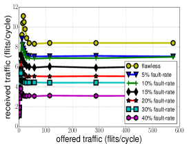
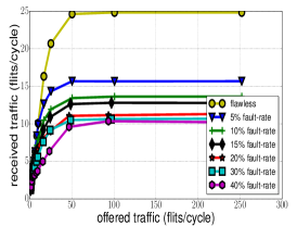
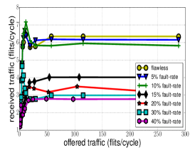
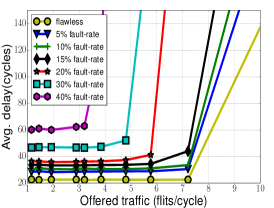
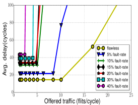
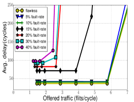
Figure 8a and 8d show the throughput and average latency results of different fault-rates under uniform-random traffic pattern, respectively. Saturation throughput quickly collapses when the fraction of faults increase over 10% and latency grows rapidly beyond 20% fault-rate. This is due to the reduced availability of communication resources and congestion caused by faults.
Figure 8b and 8e display the throughput and average latency results of different fault-rates under transpose traffic pattern, respectively. The system throughput drops significantly even at 5% fault rate. The number of received flits per cycle went from to around . The fact that further system component failuresfrom 5% to 10%seems to have a less drastic effect on the throughput or latency, highlights the importance of having even limited hardware self-healing capabilities.
Figure 8c and 8f show the throughput and average latency results of different fault-rates under bit complement traffic pattern, respectively. The results are in line with the other two benchmark data. Here the most interesting aspect is the small degradation effect seen on the throughput and latency results when increasing faults from 20% to 40%.
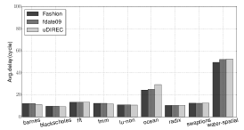

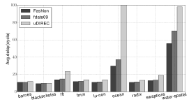

Beyond synthetic traffic, we use traces from the splash-2 benchmarks to evaluate the performance of the Fashion router architecture on 88 2D-meshes. The traces are generated from the distributed x86 multicore simulator Graphite[56] with 64 application threads. Results for light traffic loads, like blacksholes, are shown in Figure 9a-9c. The average latency remains fairly constant across these benchmarks. For heavy traffic loads like ocean_non_contiguous and water-spatial, increasing the number of faults increases the average latency.
7.5 Comparative Study
7.5.1 Baselines
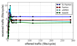
For the comparative study, we consider F(date09) by Fick et al.[57] and uDIREC[23] as our baselines. F(date09) applies flag transmission and routing entry update mechanism, while uDIREC uses a “supervisor” to maintain the topology information and according to which, it makes fault tolerance routing decisions. uDIREC architecture is shown to be more resource and performance efficient than previous works vicis[34], immunet[33] and ariadne[35]. Therefore, we omit them in the following figures for brevity.
7.5.2 Time efficiency
uDIREC was proposed to eliminate resource overhead using a scoreboard that keeps the topology information at a supervisor node. However, as reported in[23], network connectivity and performance of uDIREC are sensitive to the way breadth-first trees are grown. It may take hundreds of milliseconds to finish each reconfiguration (170ms). It also needs to run multiple iterations to find the optimized results to meet fault-tolerant requirement, which, in turn, leads to tens of seconds for a medium sized network (1616 2D-mesh) and constrains it to a centralized implementation[23].
As analyzed in Section 5, the computation complexity of the Fashion router is . The results show an average of 1384.46 clock-cycles to complete a 256 2D-mesh network, which takes negligible execution time compared with uDIREC. This is 6 to 7 orders of magnitude increase in time efficiency when running at 1Ghz.
7.5.3 Performance and resource utilization
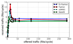
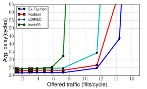
The Fashion design is not only more time efficient than the “off-line” uDIREC, but it also improves the system performance. In most cases, Fashion offers lower latency compared to F(date09) and uDRIEC. Its latency increases are more gradual than other techniques, especially for heavy traffic loads applications like ocean and water-spatial, Figure 9a-9c. The SPLASH benchmarks have relatively low-traffic loads, and do not stress the network performance as much as synthetic benchmarks. Fig 10a-10d show the throughput and average flit latency results for 88 2D-Meshes using different fault-tolerant mechanisms under uniform-random traffic. The Fashion architecture shows a 2.40% gain in throughput and 4.80% decreases in average packet latency when compared with uDIREC with 5 faults. The Ex-Fashion architecture achieves 11.09% more throughput and 6.06% less packet latency under the same experimental condition, Figure 10a and Figure 10c. When the number of faults increase to 15, the Ex-Fashion design has a throughput of 6.67 filts/cycle compared to the 5.74 filts/cycle and 5.28 filts/cycle for the Fashion and uDIREC designs, corresponding to 16.2% and 26.32% performance improvement, respectively, over these designs, Figure 10b. In terms of latency, the Ex-Fashion and Fashion architectures show average packet latency reductions of 18.66% and 14.67% over the uDIREC design, Figure 10d.
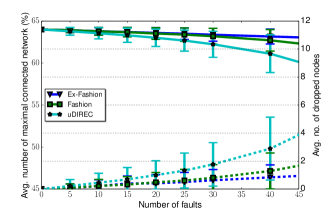
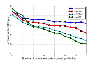
The uDIREC design only works when the underlying topology has two-way connectivity, a prerequisite that is not always present. We compare the average maximal connected network percentage and the average number of disabled faultless nodes using uDIREC[23] with the same number of faults in the 8x8 2D mesh. As shown in Figure 11, uDIREC dropped an average of 1.76 and 2.89 flawless nodes with standard deviation of 1.55 and 2.25, when there are 30 and 40 faults. In Fashion, there are 54.3% and 55.4% fewer dropped nodes with 30 and 40 faults, resulting in a higher maximal connected network percentage than uDIREC. In Ex-Fashion, there are 64.5% and 71.1% fewer dropped nodes than uDIREC with 30 and 40 faults. Further, we compared NoC performance degradation with time-dependent components defects. For these experiments, we still assumed uniform-random fault distribution, and increased the number of new permanent faults over time. Figure 12 shows average throughput results of 100,000 simulations using uniform-random traffic pattern. Fashion achieves 13.07% and 18.9% more throughput than uDIREC and F(date09) when there are 10 faults, whereas Ex-Fashion achieves 19.6% and 25.77% more throughput in the same situations.
Since uDIREC applies Up*/Down* routing and has a relatively larger number of forbidden turns, it sacrifices routing flexibility which influences the connectivity and performance of the network. The average percentage of forbidden turns in uDIREC and Fashion are 20.563% and 17.665% for 8x8 2D-meshes, results are shown in Table II. The connectivity degree of Ex-Fashion is 1.167x and 3.77x higher than Fashion with 30 and 60 faults respectively, see Table I. This is because the improved Ex-Fashion architecture can better mitigate the negative effects of single link and virtual buffer faults. The study demonstrates a significant advantage by applying bidirectional link and unified virtual channel structure to Fashion. The results of F(date09) are not shown in Figure 11, because a large portion of nodes are dropped and the maximal connected network are dramatically decreased when the number of faults exceeds 30.
| 8x8 2D mesh | 16x16 2D mesh | |||
| Fault num | uDIREC | Fashion | uDIREC | Fashion |
| 10 | 20.510% | 19.798% | 20.148% | 20.000% |
| 20 | 20.702% | 19.222% | 20.293% | 19.954% |
| 30 | 20.780% | 18.374% | 20.403% | 19.855% |
| 40 | 20.677% | 17.458% | 20.500% | 19.842% |
| 50 | 20.499% | 16.705% | 20.597% | 19.741% |
| 60 | 20.209% | 14.434% | 20.698% | 19.721% |
8 Conclusions
Current and future technology scaling effects, in particular the decreasing transistor dependability, command more effective resiliency-aware approaches to multicore and many-core systems designs. In this work, we propse and design a scalable, distributed and self-healing intelligent NoC router with minimal hardware overhead, named Fashion. The new router architecture is a self-monitoring and self-reconfiguring design that allows the on-chip network to dynamically recover from permanent component failures. The router has bidirectional links, unified virtual channel structures and distributed intelligence modules for detecting component failures and self-adjusts to mitigate their negative system performance effects. To determine the importance of a defective link or router on the network connectivity, we adopt a distributed depth first search algorithm capable of classifying faulty components as cut elements. A node-table based reconfiguration procedure is performed to provide deadlock-free and routing connectivity guarantees to the maximal connected graph of the new network topology. The Fashion router has a fully distributed operation mode with relatively constant on-chip overhead, which makes it more suitable for on-line large-scaled on-chip communication.
Fashion can also be applied in the NoC Power-gating domain to provide deadlock-free paths to the NoC traffic in dynamically changing irregular topologies. With chips becoming increasingly more power-constrained today, there is a need for intelligent NoC power-gating schemes that can reduce static power consumption and at the same time provide deadlock-free low latency paths to NoC traffic.
In this work, we mainly focused on the microarchitecture layer of the on-chip network. In future work, we will examine in detail how the Fashion router can interact with the operating system for runtime execution roll-backs, task placements, memory management and on-chip communication policies to provide a comprehensive fault-tolerant and fault-recovery mechanism to the computing system.
References
- [1] J. Howard, S. Dighe, Y. Hoskote, S. Vangal, D. Finan, G. Ruhl, D. Jenkins, H. Wilson, N. Borkar, G. Schrom et al., “A 48-core ia-32 message-passing processor with dvfs in 45nm cmos,” in Solid-State Circuits Conference Digest of Technical Papers (ISSCC), 2010 IEEE International. IEEE, 2010, pp. 108–109.
- [2] S. Bell, B. Edwards, J. Amann, R. Conlin, K. Joyce, V. Leung, J. MacKay, M. Reif, L. Bao, J. Brown, M. Mattina, C. Miao, C. Ramey, D. Wentzlaff, W. Anderson, E. Berger, N. Fairbanks, D. Khan, F. Montenegro, J. Stickney, and J. Zook, “TILE64 - processor: A 64-Core SoC with mesh interconnect,” in Proceedings of the IEEE International Solid-State Circuits Conference, 2008, pp. 88–598.
- [3] S. et al., “An 80-tile 1.28tflops network-on-chip in 65nm cmos,” in Proceedings of the Solid-State Circuits Conference, 2007, pp. 98–589.
- [4] C. Ramey, “Tile-gx100 manycore processor: Acceleration interfaces and architecture,” T ilera Corporation, 2011.
- [5] G. Chen, M. A. Anders, H. Kaul, S. K. Satpathy, S. K. Mathew, S. K. Hsu, A. Agarwal, R. K. Krishnamurthy, S. Borkar, and V. De, “16.1 a 340mv-to-0.9 v 20.2 tb/s source-synchronous hybrid packet/circuit-switched 16 16 network-on-chip in 22nm tri-gate cmos,” in Solid-State Circuits Conference Digest of Technical Papers (ISSCC), 2014 IEEE International. IEEE, 2014, pp. 276–277.
- [6] P. A. Merolla, J. V. Arthur, R. Alvarez-Icaza, A. S. Cassidy, J. Sawada, F. Akopyan, B. L. Jackson, N. Imam, C. Guo, Y. Nakamura et al., “A million spiking-neuron integrated circuit with a scalable communication network and interface,” Science, vol. 345, no. 6197, pp. 668–673, 2014.
- [7] N. E. Jerger and L.-S. Peh, “On-chip networks,” Synthesis Lectures on Computer Architecture, vol. 4, no. 1, pp. 1–141, 2009.
- [8] R. Marculescu, U. Y.Ogras, L. shiuan Peh, N. E. Jerger, and Y. Hoskote, “Outstanding research problems in noc design: system, microarchitecture, and circuit perspectives,” IEEE Transactions on Computer-Aided Design of Integrated Circuits and Systems, vol. 28, pp. 3–21, 2009.
- [9] A. Ivanov and G. D. Micheli, “The Network-on-Chip Paradigm in Practice and Research,” Design & Test of Computers, vol. 22, no. 5, pp. 399–403, 2005.
- [10] W. Dally and B. Towles, Principles and practices of interconnection networks. Morgan Kaufmann, 2004.
- [11] S. Borkar, “Designing reliable systems from unreliable components: the challenges of transistor variability and degradation,” Micro, IEEE, vol. 25, no. 6, pp. 10–16, 2005.
- [12] V. J. Reddi and D. Brooks, “Resilient architectures via collaborative design: Maximizing commodity processor performance in the presence of variations,” Computer-Aided Design of Integrated Circuits and Systems, IEEE Transactions on, vol. 30, no. 10, pp. 1429–1445, 2011.
- [13] L. Wilson, “International technology roadmap for semiconductors (itrs),” 2013.
- [14] C. Yu, Modeling of Temporal Reliability Degradation. Springer US, 2011.
- [15] J. H. Collet, P. Zajac, M. Psarakis, and D. Gizopoulos, “Chip self-organization and fault tolerance in massively defective multicore arrays,” Dependable and Secure Computing, IEEE Transactions on, vol. 8, no. 2, pp. 207–217, 2011.
- [16] S. K. Sastry Hari, M.-L. Li, P. Ramachandran, B. Choi, and S. V. Adve, “mswat: Low-cost hardware fault detection and diagnosis for multicore systems,” in Proceedings of the 42Nd Annual IEEE/ACM International Symposium on Microarchitecture, ser. MICRO 42. New York, NY, USA: ACM, 2009, pp. 122–132. [Online]. Available: http://doi.acm.org/10.1145/1669112.1669129
- [17] M. Prvulovic, Z. Zhang, and J. Torrellas, “Revive: cost-effective architectural support for rollback recovery in shared-memory multiprocessors,” in Computer Architecture, 2002. Proceedings. 29th Annual International Symposium on, 2002, pp. 111–122.
- [18] S. Borkar, “Challenges in reliable system design in the presence of transistor variability and degradation,” IEEE Micro, vol. 25, no. 6, pp. 10–16, 2005.
- [19] D. Sylvester, D. Blaauw, and E. Karl, “Elastic: An adaptive self-healing architecture for unpredictable silicon,” Design & Test of Computers, IEEE, vol. 23, no. 6, pp. 484–490, 2006.
- [20] A. DeOrio, K. Aisopos, V. Bertacco, and L.-S. Peh, “Drain: Distributed recovery architecture for inaccessible nodes in multi-core chips,” in Proceedings of the 48th Design Automation Conference. ACM, 2011, pp. 912–917.
- [21] Y. B. Kim and Y. bin Ki, “Fault tolerant source routing for network-on-chip,” in 22nd IEEE International Symposium on Defect and Fault-Tolerance in VLSI Systems, 2007, pp. 12–20.
- [22] D. Park, C. Nicopoulos, J. Kim, N. Vijaykrishnan, and C. Das, “Exploring fault-tolerant network-on-chip architectures,” in Dependable Systems and Networks, 2006. DSN 2006. International Conference on, June 2006, pp. 93–104.
- [23] R. Parikh and V. Bertacco, “udirec: unified diagnosis and reconfiguration for frugal bypass of noc faults,” in Proceedings of the 46th Annual IEEE/ACM International Symposium on Microarchitecture. ACM, 2013, pp. 148–159.
- [24] A. Shafiee, M. Zolghadr, M. Arjomand, and H. Sarbazi-Azad, “Application-aware deadlock-free oblivious routing based on extended turn-model,” in Proceedings of the International Conference on Computer-Aided Design. IEEE Press, 2011, pp. 213–218.
- [25] B. Fu, Y. Han, J. Ma, H. Li, and X. Li, “An abacus turn model for time/space-efficient reconfigurable routing,” in Computer Architecture (ISCA), 2011 38th Annual International Symposium on. IEEE, 2011, pp. 259–270.
- [26] P. Ren, M. Kinsy, and N. Zheng, “Fault-aware load-balancing routing for 2d-mesh and torus on-chip network topologies,” Computers, IEEE Transactions on, vol. PP, no. 99, pp. 1–1, 2015.
- [27] L. Chen and T. M. Pinkston, “Nord: Node-router decoupling for effective power-gating of on-chip routers,” in Proceedings of the 2012 45th Annual IEEE/ACM International Symposium on Microarchitecture, ser. MICRO-45. Washington, DC, USA: IEEE Computer Society, 2012, pp. 270–281. [Online]. Available: http://dx.doi.org/10.1109/MICRO.2012.33
- [28] A. Samih, R. Wang, A. Krishna, C. Maciocco, T. C. Tai, and Y. Solihin, “Energy-efficient interconnect via router parking,” in 19th IEEE International Symposium on High Performance Computer Architecture, HPCA 2013, Shenzhen, China, February 23-27, 2013, 2013, pp. 508–519. [Online]. Available: http://dx.doi.org/10.1109/HPCA.2013.6522345
- [29] R. Parikh, R. Das, and V. Bertacco, “Power-aware nocs through routing and topology reconfiguration,” in Proceedings of the 51st Annual Design Automation Conference, ser. DAC ’14. New York, NY, USA: ACM, 2014, pp. 162:1–162:6. [Online]. Available: http://doi.acm.org/10.1145/2593069.2593187
- [30] M. Gomez, N. Nordbotten, J. Flich, P. Lopez, A. Robles, J. Duato, T. Skeie, and O. Lysne, “A routing methodology for achieving fault tolerance in direct networks,” IEEE transactions on Computers, pp. 400–415, 2006.
- [31] Y. Fukushima, M. Fukushi, and S. Horiguchi, “Fault-tolerant routing algorithm for network on chip without virtual channels,” in Defect and Fault Tolerance in VLSI Systems, 2009. DFT’09. 24th IEEE International Symposium on. IEEE, 2009, pp. 313–321.
- [32] P. Ren, Q. Meng, X. Ren, and N. Zheng, “Fault-tolerant routing for on-chip network without using virtual channels,” in Proceedings of the The 51st Annual Design Automation Conference on Design Automation Conference. ACM, 2014, pp. 1–6.
- [33] V. Puente, J. A. Gregorio, F. Vallejo, and R. Beivide, “Immunet: A cheap and robust fault-tolerant packet routing mechanism,” in ACM SIGARCH Computer Architecture News, vol. 32. IEEE Computer Society, 2004, p. 198.
- [34] D. Fick, A. DeOrio, J. Hu, V. Bertacco, D. Blaauw, and D. Sylvester, “Vicis: a reliable network for unreliable silicon,” in Proceedings of the 46th Annual Design Automation Conference. ACM, 2009, pp. 812–817.
- [35] K. Aisopos, A. DeOrio, L.-S. Peh, and V. Bertacco, “Ariadne: Agnostic reconfiguration in a disconnected network environment,” in Parallel Architectures and Compilation Techniques (PACT), 2011 International Conference on. IEEE, 2011, pp. 298–309.
- [36] M. D. Schroeder, A. D. Birrell, M. Burrows, H. Murray, R. M. Needham, T. L. Rodeheffer, E. H. Satterthwaite, and C. P. Thacker, “Autonet: A high-speed, self-configuring local area network using point-to-point links,” Selected Areas in Communications, IEEE Journal on, vol. 9, no. 8, pp. 1318–1335, 1991.
- [37] C. Iordanou, V. Soteriou, and K. Aisopos, “Hermes: Architecting a top-performing fault-tolerant routing algorithm for networks-on-chips,” in Computer Design (ICCD), 2014 32nd IEEE International Conference on. IEEE, 2014, pp. 424–431.
- [38] R. Parikh and V. Bertacco, “Formally enhanced runtime verification to ensure noc functional correctness,” in Proceedings of the 44th Annual IEEE/ACM International Symposium on Microarchitecture. ACM, 2011, pp. 410–419.
- [39] S. Murali, T. Theocharides, N. Vijaykrishnan, M. J. Irwin, L. Benini, and G. De Micheli, “Analysis of error recovery schemes for networks on chips,” IEEE Design & Test of Computers, vol. 22, no. 5, pp. 434–442, 2005.
- [40] J. Kim, C. Nicopoulos, D. Park, V. Narayanan, M. S. Yousif, and C. R. Das, “A gracefully degrading and energy-efficient modular router architecture for on-chip networks,” in ACM SIGARCH Computer Architecture News, vol. 34. IEEE Computer Society, 2006, pp. 4–15.
- [41] M. Palesi, S. Kumar, and V. Catania, “Leveraging partially faulty links usage for enhancing yield and performance in networks-on-chip,” Computer-Aided Design of Integrated Circuits and Systems, IEEE Transactions on, vol. 29, no. 3, pp. 426–440, 2010.
- [42] A. Prodromou, A. Panteli, C. Nicopoulos, and Y. Sazeides, “Nocalert: An on-line and real-time fault detection mechanism for network-on-chip architectures,” in Microarchitecture (MICRO), 2012 45th Annual IEEE/ACM International Symposium on. IEEE, 2012, pp. 60–71.
- [43] S. Shamshiri, A.-A. Ghofrani, and K.-T. Cheng, “End-to-end error correction and online diagnosis for on-chip networks,” in Test Conference (ITC), 2011 IEEE International. IEEE, 2011, pp. 1–10.
- [44] P. Ren, M. Lis, M. H. Cho, K. S. Shim, C. W. Fletcher, O. Khan, N. Zheng, and S. Devadas, “Hornet: A cycle-level multicore simulator,” Computer-Aided Design of Integrated Circuits and Systems, IEEE Transactions on, vol. 31, no. 6, pp. 890–903, 2012.
- [45] P. Ren, X. Ren, S. Sane, M. Kinsy, and N. Zheng, “A deadlock-free and connectivity-guaranteed methodology for achieving fault-tolerance in on-chip networks,” Computers, IEEE Transactions on, vol. PP, no. 99, pp. 1–1, 2015.
- [46] W. Dally and B. Towles, Principles and Practices of Interconnection Networks. San Francisco, CA, USA: Morgan Kaufmann Publishers Inc., 2003.
- [47] C. J. Glass and L. M. Ni, “The turn model for adaptive routing,” in Proceedings of the International Symposium on Computer Architecture. Queensland, Australia: ACM, 1992, pp. 278–287.
- [48] J. Wu, “A fault-tolerant and deadlock-free routing protocol in 2d meshes based on odd-even turn model,” IEEE Transactions on Computers, pp. 1154–1169, 2003.
- [49] A. DeOrio, D. Fick, V. Bertacco, D. Sylvester, D. Blaauw, J. Hu, and G. Chen, “A reliable routing architecture and algorithm for nocs,” Computer-Aided Design of Integrated Circuits and Systems, IEEE Transactions on, vol. 31, no. 5, pp. 726–739, 2012.
- [50] R. Tarjan, “Depth-first search and linear graph algorithms,” SIAM journal on computing, vol. 1, no. 2, pp. 146–160, 1972.
- [51] T. H. Cormen, C. E. Leiserson, R. L. Rivest, and C. Stein, Introduction to algorithms, 2009, 2009.
- [52] M. H. Cho, M. Lis, K. S. Shim, M. Kinsy, T. Wen, and S. Devadas, “Oblivious routing in on-chip bandwidth-adaptive networks,” in Proceedings of the 2009 18th International Conference on Parallel Architectures and Compilation Techniques, ser. PACT ’09. Washington, DC, USA: IEEE Computer Society, 2009, pp. 181–190. [Online]. Available: http://dx.doi.org/10.1109/PACT.2009.41
- [53] Y. C. Lan, H. A. Lin, S. H. Lo, Y. H. Hu, and S. J. Chen, “A bidirectional noc (binoc) architecture with dynamic self-reconfigurable channel,” IEEE Transactions on Computer-Aided Design of Integrated Circuits and Systems, vol. 30, no. 3, pp. 427–440, 2011.
- [54] W.-C. Tsai, D.-Y. Zheng, S.-J. Chen, and Y.-H. Hu, “A fault-tolerant noc scheme using bidirectional channel,” in Design Automation Conference (DAC), 2011 48th ACM/EDAC/IEEE, June 2011, pp. 918–923.
- [55] C. A. Nicopoulos, D. Park, J. Kim, N. Vijaykrishnan, M. S. Yousif, and C. R. Das, “Vichar: A dynamic virtual channel regulator for network-on-chip routers,” in Proceedings of the 39th Annual IEEE/ACM International Symposium on Microarchitecture, ser. MICRO 39. Washington, DC, USA: IEEE Computer Society, 2006, pp. 333–346. [Online]. Available: http://dx.doi.org/10.1109/MICRO.2006.50
- [56] J. E. Miller, H. Kasture, G. Kurian, C. Gruenwald, N. Beckmann, C. Celio, J. Eastep, and A. Agarwal, “Graphite: A distributed parallel simulator for multicores,” in High Performance Computer Architecture (HPCA), 2010 IEEE 16th International Symposium on. IEEE, 2010, pp. 1–12.
- [57] D. Fick, A. DeOrio, G. Chen, V. Bertacco, D. Sylvester, and D. Blaauw, “A highly resilient routing algorithm for fault-tolerant nocs,” in Proceedings of the Conference on Design, Automation and Test in Europe. European Design and Automation Association, 2009, pp. 21–26.