Giant microwave-induced -periodic magnetoresistance oscillations in a two-dimensional electron gas with a bridged-gate tunnel point contact
Abstract
We have studied the magnetoresistance of the quantum point contact fabricated on the high mobility two-dimensional electron gas (2DEG) exposed to microwave irradiation. The resistance reveals giant -periodic oscillations with the relative amplitude of up to % resulting from the propagation and interference of the edge magnetoplasmons (EMPs) in the sample. This giant photoconductance is attributed to the considerably large local electron density modulation in the vicinity of the point contact. We have also analyzed the oscillation periods of the resistance oscillations and, comparing the data with the EMP theory, extracted the EMP interference length . We have found that the length substantially exceeds the distance between the contact leads but rather corresponds to the distance between metallic contact pads measured along the edge of the 2DEG. This resolves existing controversy in the literature and should help to properly design highly sensitive microwave and terahertz spectrometers based on the discussed effect.
pacs:
73.23.-bA number of interesting magnetotransport phenomena were discovered in recent years in a two-dimensional electron gas (2DEG) placed in a perpendicular magnetic field and exposed to microwave (MW) irradiation. In low magnetic fields, corresponding to the condition , the so called microwave-induced resistance oscillations (MIRO), with zero-resistance states, were observed Zudov et al. (2001); Ye et al. (2001); Mani et al. (2002); Zudov et al. (2003); here and are the cyclotron and microwave frequencies and is the electron effective mass. These oscillations of the diagonal resistance are periodic in and are especially pronounced at low temperatures K in samples with a high electron mobility.
In the opposite regime of higher magnetic fields, , another type of magnetoresistance oscillations was discovered Kukushkin et al. (2004). These oscillations are periodic in and were explained by the excitation and interference of edge magnetoplasmonsVolkov and Mikhailov (1988) (EMPs) in the sample. The incident microwave radiation excites oscillating (dipole) electric field at the boundaries between the 2DEG and metallic contacts. These dipole fields generate plasma waves – EMPs – propagating along the sample edge between the contacts on which the magnetoresistance is measured. Due to the interference of EMPs, generated by different contacts, oscillates as a function of the parameter , where is the EMP wave-vector and is the inter-contact distance Kukushkin et al. (2004). In strong magnetic fields is proportional to , where is the electron density Volkov and Mikhailov (1988); Mikhailov (2006). This leads to the -periodic oscillations with the period . This theoretically predicted dependence was confirmed by the experiments Kukushkin et al. (2004, 2005). EMPs have a much smaller damping, as compared to the bulk magnetoplasmons,Volkov and Mikhailov (1988); Mikhailov (2006) and, in contrast to the MIRO-ZRS effect, the EMP-related oscillations do not require low temperatures and samples with the very high electron mobility: they were observed at least up to K Kukushkin et al. (2005). These EMP properties make the considered phenomenon especially promising for the creation of miniature microwave frequency-sensitive detectors and spectrometers.
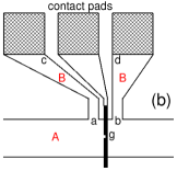
The frequency and density dependence of the oscillation period , experimentally observed in the first papers Kukushkin et al. (2004, 2005), was confirmed in a later publication by Stone et al. Stone et al. (2007). However, in contrast to Kukushkin et al. (2004, 2005), they found that does not depend on the distance between the contacts. This contradiction remains unexplained so far; actually, it raises the question which length should be understood under in the discussed phenomenon. Notice that both in Refs. Kukushkin et al. (2004, 2005) and Ref. Stone et al. (2007) was assumed to be equal to the distance between the points and in Figure 1(b), i.e. the points where the contact leads (made out of the 2DEG) touch the 2DEG channel.
In this paper we investigate the EMP-related magnetoresistance oscillations in GaAs/AlGaAs quantum-well structures. Our work differs from the previous publications Kukushkin et al. (2004, 2005); Stone et al. (2007) in three essential aspects. First, the distance in our samples ( m) is almost two orders of magnitude shorter than in Refs. Kukushkin et al. (2004, 2005); Stone et al. (2007). If the oscillation period was proportional to , we would observe more than ten times larger period than in Refs. Kukushkin et al. (2004, 2005); Stone et al. (2007). But in our experiment T, which is close to the oscillation periods in Kukushkin et al. (2004, 2005); Stone et al. (2007). Second, we have performed a more careful, quantitative comparison of our experimental data with the theory Volkov and Mikhailov (1988) and extracted the value of from the experimental data. It turns out to be of 1 mm scale which is much larger than but is of order of the distance between the metallic contact pads measured along the edge of the 2DEG. Third, our samples were covered by a thin metallic gate forming a bridged-gate quantum point contact (QPC) Levin et al. (2015). Recently, in Ref. Levin et al. (2015), we have shown (at ) that the Hall bars with the bridged-gate QPC demonstrate a two-three orders of magnitude higher sensitivity to the microwave irradiation than the structures with a traditional split-gate QPC. In the present work (, bridged-gate) we have found a much higher oscillation amplitude of the -periodic oscillations () than in the ungated structures Kukushkin et al. (2004, 2005); Stone et al. (2007) or in structures with a split-gate QPC Dorozhkin et al. (2005) (). Our results lead to a better understanding of the physics of the EMP-related magnetoresistance oscillations and pave the way to the creation of more efficient frequency sensitive detectors of microwave and terahertz radiation.
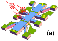
Our specimens are narrow ( nm) quantum wells with the electron density cm-2 and the mobility of cm2/V s at K. We measure the resistance on a conventional Hall bar patterned structure, which is designed for multi-terminal measurements. The sample consists of three m wide consecutive segments of different length (, , m), and eight voltage probes, see Figure 1(a). High quality Ohmic contacts to a 2DEG are made using AuGeNi metalization followed by an annealing. Two thin metallic gates (bridged gate QPCs) are sputtered on the central parts of the left and right segments of the Hall bar. The middle segment was used to measure the resistance of the unpatterned 2D electron gas. Four devices were studied and the similar results were obtained. The measurements were carried out in a VTI cryostat with a waveguide to deliver MW irradiation (the frequency range 110 to 170 GHz, the power density mW/cm2) down to the sample and by using a conventional lock-in technique to measure the longitudinal resistance .
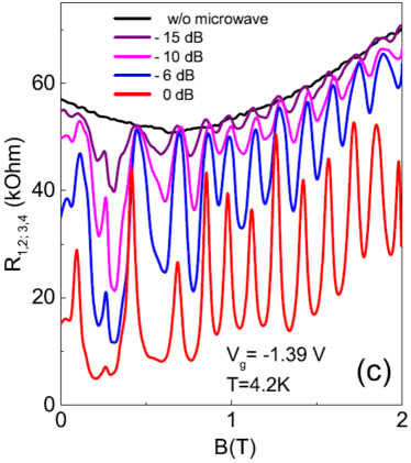
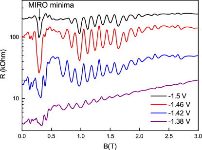
Figure 1(c) shows the magnetoresistance of the QPC at the temperature K, the frequency GHz and several values of the microwave power attenuation factor. The microwave irradiation leads to the strong suppression of the resistance at zero magnetic field Levin et al. (2015). At T (corresponds to ) the resistance reveals the large -periodic magnetoresistance oscillations. Figure 2 illustrates the magnetoresistance at different (fixed) gate voltages varying from the open-contact regime ( k) to the close-contact regime (); here is the QPC resistance at . The oscillation frequency shows no change with , while the resistance increases by several orders of magnitude. The amplitudes of the -periodic oscillations are vanishingly small in the unbiased (), as well as in the unpatterned (no gate), structures. When the absolute value of grows, the oscillation amplitudes first increase (blue and red curves in Figure 2) but then decrease again (black curve) since at very large negative gate voltages the contacts 3 and 4 becomes decoupled.
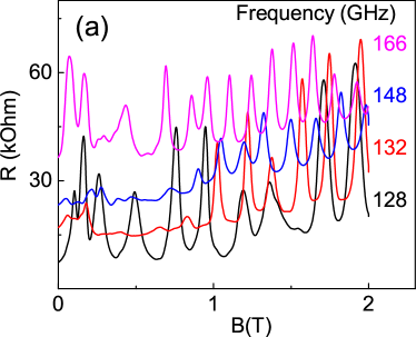
Let us analyze the oscillating behavior of quantitatively. Figure 3(a) shows the QPC resistance at four chosen frequencies from the interval GHz. At T one sees about ten maxima of the dependence, with the oscillation periods growing with the decreasing frequency. We assume Kukushkin et al. (2004) that the oscillations are caused by the interference of EMPs excited from two points at the sample boundary separated by a length (e.g. by the distance between some contacts) and the maxima of are the case when is integer. Then the length can be found as follows.
The spectrum of EMPs running along the boundary of a semi-infinite 2DEG is determined by the dispersion relation Volkov and Mikhailov (1988)
| (1) |
where and are the EMP wavevector and frequency, is the 2DEG Drude conductivity tensor and
| (2) |
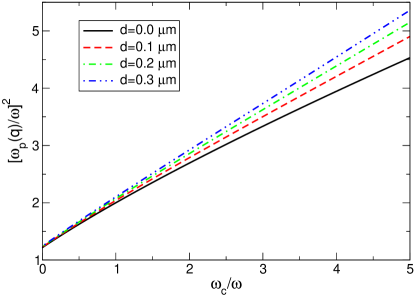
is the effective dielectric function of the structure air – dielectric layer (thickness , dielectric constant ) – 2DEG – dielectric substrate (infinite thickness, dielectric constant ). If (the thickness is typically very small, m), the dispersion relation (1)–(2) can be plotted as the dimensionless wave-vector versus dimensionless magnetic field ; here is the 2D plasmon frequency at and . This dependence is shown by the black solid curve in Fig. 4. Other curves in this Figure show the -vs- dependence at the finite dielectric cover-layer thickness . At a finite the EMP spectrum additionally depends on the dimensionless parameter ; for the density and the frequency we have chosen parameters of our experiment, see Figure 4 caption. The theoretical curves start (at ) from the value which determines the spectrum of edge plasmons in zero magnetic field, see Eq. (39) in Ref. Volkov and Mikhailov (1988).
To compare now the theoretical curves of Fig. 4 with the experimentally found EMP-interference maxima in Fig. 3(a) we introduce in (2) the length , , and consider Eqs. (1)–(2) as an implicit relation between the interference parameter and four dimensionless quantities
| (3) |
The electron density , the GaAs dielectric constant () and the thickness of the dielectric layer above the 2DEG ( nm) are known in Eq. (3), therefore we can plot as a function of and fit these curves to the experimental points considering as a fitting parameter.
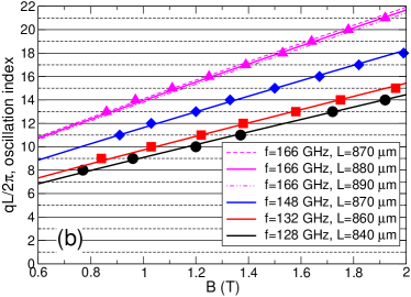
Specifically, we proceed as follows. Consider, for example, the upper (magenta) curve in Figure 3(a). It corresponds to the frequency GHz and has eight oscillation periods (nine maxima) in the interval T. Plotting the theoretical curve we choose the length so that inside this interval there were exactly eight oscillation periods. This gives us both the integer indexes (from to ), unambiguously ascribed to each of the nine maxima of , and the length m, see Figure 3(b). The accuracy of this method is quite high: a closer look at the Figure shows that the two thin magenta curves corresponding to 870 and 890 m give a worse fit to the experimental data.
Using the same method we fit three other sets of experimental data from Figure 3(a). The lengths found for 148, 132 and 128 GHz are , 860 and 840 m, Figure 3(b). Thus found values of slightly decrease with the frequency but the whole change of for lying between 166 and 128 GHz does not exceed 5 %. Thus we conclude that the characteristic length which determines the EMP-related oscillations is much larger than the distance in Figure 1 (inset) and is of the mm scale. This corresponds, approximately, to the distance between the points and in our experiment.
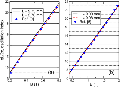
Similarly, we have also analyzed the data of Refs. Stone et al. (2007) and Kukushkin et al. (2004). Figure 5 shows the results of the fitting procedure for two selected experimental curves from these papers. The interference lengths found this way are about and mm respectively which is also larger than the corresponding distances or mm in Refs. Stone et al. (2007) and Kukushkin et al. (2004). Thus both in our work and in the previous publications Kukushkin et al. (2004); Stone et al. (2007) the length extracted from the experimentally observed -periodic oscillations is substantially larger than .
What exactly determines the interference length is difficult to ascertain because the real geometry of the 2DEG with attached contact pads is complicated in our experiment and unknown in Refs. Stone et al. (2007); Kukushkin et al. (2004). In all cases, however, the length is close to the average distance between the contact pads, counted if to move along the boundary of the 2DEG (or, in our work, between the contact pad and the QPC). This agrees with the simple physical picture of EMPs running along the edge of the 2DEG and generated at the boundaries of regions with substantially different electron densities,Kukushkin et al. (2004) i.e., at the boundaries 2DEG – metal contacts (the points , in Figure 1(b)).
One more interesting feature that we have observed in our experiment is the very large amplitude of -periodic oscillations () which is substantially larger than in previous publications Kukushkin et al. (2004, 2005); Stone et al. (2007); Dorozhkin et al. (2005) (). Actually the oscillations in our experiment look like a set of narrow resonances with a high quality factor. We attribute this very useful feature to the use of the bridged-gate QPC which was shown to substantially increase the local microwave field in the near contact area, see Ref. Levin et al. (2015).
To summarize, we have experimentally studied the -periodic microwave induced magnetoresistance oscillations in a GaAs/AlGaAs quantum well samples. Comparing experimental results with the theory we have established that the EMP interference length responsible for the period of the magnetoresistance oscillations is presumably determined by the distance between real metallic contacts (contact pads) measured along the boundary of the 2DEG. This partly explains the contradiction between the earlier published results Kukushkin et al. (2004); Stone et al. (2007), but in order to reliably establish which length or lengths are ultimately responsible for the formation of EMP-related oscillations further experimental studies on samples with possibly simple geometry of the 2DEG and contact pads are needed, together with the corresponding theoretical modeling. We have also demonstrated that using the bridged-gate QPC one can substantially increase the amplitude of the -periodic oscillations and hence the sensitivity of the microwave detectors and spectrometers based on the discussed phenomenon.
We thank N. A. Savostianova for assistance and O. E. Raichev for helpful discussions. The financial support of this work by FAPESP, CNPq (Brazilian agencies), RFBI (No 17-02-00384) and RAS (No 16-116021510194-3) is acknowledged.
References
- Zudov et al. (2001) M. A. Zudov, R. R. Du, J. A. Simmons, and J. L. Reno, Phys. Rev. B 64, 201311 (2001).
- Ye et al. (2001) P. D. Ye, L. W. Engel, D. C. Tsui, J. A. Simmons, J. R. Wendt, G. A. Vawter, and J. L. Reno, Appl. Phys. Lett. 79, 2193 (2001).
- Mani et al. (2002) R. G. Mani, J. H. Smet, K. von Klitzing, V. Narayanamurti, W. B. Johnson, and V. Umansky, Nature 420, 646 (2002).
- Zudov et al. (2003) M. A. Zudov, R. R. Du, L. N. Pfeiffer, and K. W. West, Phys. Rev. Lett. 90, 046807 (2003).
- Kukushkin et al. (2004) I. V. Kukushkin, M. Y. Akimov, J. H. Smet, S. A. Mikhailov, K. von Klitzing, I. L. Aleiner, and V. I. Falko, Phys. Rev. Lett. 92, 236803 (2004).
- Volkov and Mikhailov (1988) V. A. Volkov and S. A. Mikhailov, Sov. Phys.-JETP 67, 1639 (1988).
- Mikhailov (2006) S. A. Mikhailov, Appl. Phys. Lett. 89, 042109 (2006).
- Kukushkin et al. (2005) I. V. Kukushkin, S. A. Mikhailov, J. H. Smet, and K. von Klitzing, Appl. Phys. Lett. 86, 044101 (2005).
- Stone et al. (2007) K. Stone, C. L. Yang, Z. Q. Yuan, R. R. Du, L. N. Pfeiffer, and K. W. West, Phys. Rev. B 76, 153306 (2007).
- Levin et al. (2015) A. D. Levin, G. M. Gusev, Z. D. Kvon, A. K. Bakarov, N. A. Savostianova, S. A. Mikhailov, E. E. Rodyakina, and A. V. Latyshev, Appl. Phys. Lett. 107, 072112 (2015).
- Dorozhkin et al. (2005) P. S. Dorozhkin, S. V. Tovstonog, S. A. Mikhailov, I. V. Kukushkin, J. H. Smet, and K. von Klitzing, Appl. Phys. Lett. 87, 092107 (2005).