Overcoming limits to near-field radiative heat transfer in uniform planar media through multilayer optimization
Abstract
Radiative heat transfer between uniform plates is bounded by the narrow range and limited contribution of surface waves. Using a combination of analytical calculations and numerical gradient-based optimization, we show that such a limitation can be overcome in complicated multilayer geometries, allowing the scattering and coupling rates of slab resonances to be altered over a broad range of evanescent wavevectors. We conclude that while the radiative flux between two inhomogeneous slabs can only be weakly enhanced, the flux between a dipolar particle and an inhomogeneous slab—proportional to the local density of states—can be orders of magnitude larger, albeit at the expense of increased frequency selectivity. A brief discussion of hyperbolic metamaterials shows that they provide far less enhancement than optimized inhomogeneous slabs.
I Introduction
Radiative heat transfer (RHT) between two bodies separated by a vaccuum gap and held at different temperatures is limited by Stefan–Boltzmann’s law in the far field, i.e. for gap distances much larger than the thermal wavelength (several microns at ambient temperature). This limitation no longer applies in the near field, where the physics is dramatically altered by the presence of evanenscent tunneling of photons. For instance, the coupling of bound surface modes (e.g. phonon-polaritons in dielectrics) can result in orders-of-magnitude larger flux rates basu2009review ; volokitin2007near ; joulain2005review ; otey2014fluctuational ; liu2015outlook . Frequency-selective bounds to RHT between arbitrarily shaped homogeneous bodies were recently established miller2015shape , demonstrating that typically considered configurations (e.g. two parallel slabs of ordinary materials) tend to be highly suboptimal. The possibility of increasing both far and near-field heat exchange through geometry has attracted a remarkable amount of attention over the last several deades due to its relevance in many technological applications, from thermophotovoltaic (TPV) energy conversion basu2009review to near-field thermal lithography litography .
In the far field, where the traditional, ray-optical form of Kirchoff’s law (equating emissivity and absorptivity) is applicable wang2011direct , computational advances have made it possible to exploit a variety of optimization strategies (exploiting a variety of methods, e.g. random-walk, genetic and particle swarm algorithms, and the Taguchi method) to realize, for instance, selective and/or wide-angle absorbers whose emissivity can come close to the blackbody limits Celanovic2004 ; Drevillon2007 ; david2007optimization ; Ghebrebrhan2009 ; sergeant2009design ; chen2010profile ; chen2011polarization ; Nefzaoui2012 ; WangSolar ; Simovski2013 ; wangLDOS ; anderson2015optimized , and whose objective is usually that of increasing the performance of a TPV device or solar cell. More recently, development of adjoint optimization techniques in combination with fast numerical EM solvers have allowed application of large-scale optimization JensenRev methods capable of efficiently tackling problems involving much higher number of degrees of freedom. For instance, these inverse-design techniques have been exploited to enhance the far-field efficiency of solar-cell absorbers Ghebrebrhan2009 ; Ganapati , tailor the spectrum of incandescent sources NatureInc , and to increase the functionality of photonic-crystal absorbers Borel and TPV systems Bermel2010 . Far less explored is the near field, where the possibility of tuning and amplifying RHT has been investigated mainly through parametric studies, i.e. shape optimization, involving only a few degrees of freedoms. For example, several authors have studied the role of thin films in amplifying the heat flux between planar objects BiehsEJB07 ; ben2009near ; wangF2011 ; boriskina2015enhancement . Others have focused on enhancing desirable optical properties by examining variations with respect to Drude or Drude–Lorentz model parameters wang09 ; wangF2011 ; Zhao12 ; Nefzaoui2013 , e.g. through doping RousseauAPL09 ; BasuJH2010 ; Zhao12 . Various geometries such as dielectric LiuAPL14 ; fu2006nanoscale ; Liu2015enhanced and metallic Guerout2012grating ; Dai1 ; Dai2 ; Dai3 ; YangPRL ; MessinaarXiv ; chalabi2016focused ; fernandez2017enhancing gratings, and even finite bodies ramezan2016radiative ; chalabi2015effect ; chalabi2015near have been recently considered. Less restrictive inverse-design techniques have been recently employed to improve the performances of heat-assisted magnetic recording (HAMR) head Bhargava . Relatedly, some authors have also addressed the modulation and optimization of a closely related quantity, the near-field electromagnetic local density of states (LDOS). For instance, liLDOS performed a parametric study of the LDOS close to a multilayer arrangement of silicon carbide and silicon thin slabs as a function of distance and number of layers while benabdallahLDOS09 employed genetic algorithms to optimize the LDOS in proximity of a multilayer binary structure composed of alluminium and lossless dielectric layers.
In this paper, we apply adjoint, large-scale RHT optimization with the goal of enhancing RHT in two of the most commonly studied scenarios of two planar parallel slabs and a dipolar particle in proximity to a slab. In particular, we relax the typical assumption of homogeneous materials and consider instead arbitrary dielectric profiles (along the gap direction) in planar geometries. In order to fully address the richness of a non-uniform permittivity, we employ gradient-based optimization over a large number of degrees of freedom (number of layers 1000), a regime where previously explored techniques based on global, derivative-free optimization are bound to fail. We demonstrate that appropriately optimized, multilayer structures can lead to larger RHT compared to the best possible homogeneous thin films. Our results are motivated by and extend previously derived frequency-selective bounds for homogeneous, planar media miller2015shape , quantifying the maximum flux rates that can be achieved at any given frequency through the careful interference or “rate matching” of scattered and absorbed surface waves; such a condition can only be satisfied at a single wavevector in uniform slabs but can be much more broadband in inhomogeneous media. We find that with respect to uniform slabs, RHT between inhomogeneous slabs can only be weakly enhanced, with the optimized structures approaching the bounds.
Much larger enhancements are possible in the dipole–plate geometry, where in principle RHT for sufficient small dipole—proportional to the local density of states (LDOS)—can be infinite miller2015shape ; miller2016fundamental ; Maslovski16 . We provide theoretical bounds for the flux contribution of each wavevector in semi-infinite, uniform media and discover structures that can approach these bounds over a broad range of wavevectors, limited mainly by the difficult task of achieving perfect and broadband absorption of waves close to the light line. Specifically, we find that the optimization procedure is able to produce finite enhancements, limited only by the finite numerical discretization (number of layers) and sharp dielectric variations of the structures: these can reach two orders of magnitude at mid-range separations but at the expense of frequency selectivity. In the deep near field (), on the other hand, the condition leading to maximal LDOS is satisfied by the ideal resonant plasmonic condition () in a uniform medium and is therefore bounded by previously derived bounds on homogeneous media miller2015shape . We remark that while the problem of enhancing RHT between planar materials appears highly constrained and difficult to tackle, there is much more room for improvements and tunability when it comes to tailoring the LDOS in the vicinity of a planar body through multilayering, which could also be of interest in other contexts, such as in near-field imaging ramakrishna2003imaging ; zhang2008superlenses .
Finally, although we only consider inhomogeneous slabs composed of dielectric media, we argue that similar enhancements are expected in the case of inhomogeneous, magnetically anisotropic materials. This is exemplified, for instance, in the case of hyperbolic metamaterials (HMM), which were recently considered in the study of radiative heat transfer in multilayer geometries HMMs . In particular, focusing on the case of uniaxial media, we show that at any separation HMMs suffer from the same limitations of uniform thin films and thus do not yield significant flux enhancements.
II Formulation
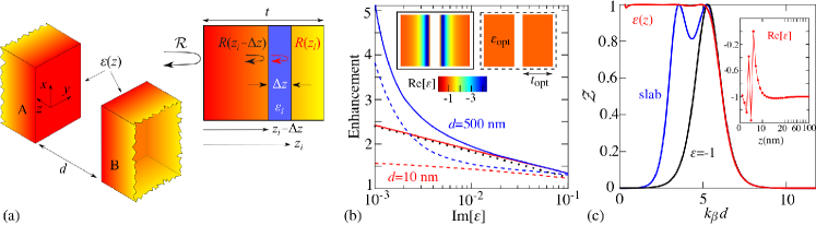
In what follows, we consider RHT in geometries involving slabs of arbitrarily varying dielectric profiles along the direction perpendicular to the slab–vacuum interfaces, depicted in Fig. 1(a). RHT in such a setup can be described via the fluctuational electrodynamics framework developed by Rytov, Polder, and van Hove (see Refs. basu2009review ; joulain2005review and references therein). Specifically, we extend a recently developed formulation of this problem messina2011pra ; messina2014pra that expresses the flux in scenarios involving two and three uniform bodies as a function of their reflection and transmission matrices. This approach, together with a semi-analytic expression for the reflection matrix of a slab of arbitrary , enables gradient-based optimizations of RHT. Since the system is time and translationally invariant in –, the reflection matrix is diagonal in the frequency , parallel wavevector , and polarization , and can be cast as the solution of a differential equation, derived as follows. Consider for each slab a local coordinate system such that lies at the interface between each slab and the vacuum gap (of size ) and points away from the interface. Given a slab occupying the region (where and is the possibly infinite thickness of the slab), let be the coefficient describing the reflection on the left side, i.e. at the interface . Adding a film of infinitesimal thickness at , the reflection coefficient of the combined system (at the interface) is given by , where and are the reflection and transmission coefficients of the film, respectively. Taking the limit , one obtains the following nonlinear differential equation:
| (1) |
which, in combination with the boundary condition , describing the absence of the slab (thus a vanishing reflection coefficient) for , completely specifies the reflectivity of the system. Here is the ordinary Fresnel reflection coefficient, the perpendicular wavevector inside the slab. Note that in the limiting case of uniform , Eq. (1) yields the well-known solution , going to in the case of a semi-infinite slab (). Equation 1 can be directly solved to obtain the reflection coefficient of a slab of arbitrarily varying : in the case of the two slabs of Fig. 1(a), one would also need to specify the boundary conditions for both slabs A and B. Once the function is known for each slab, represents the reflection coefficient needed to calculate RHT and analyze the possible enhancements arising from a given , investigated below via analytical and optimization techniques.
We seek dielectric profiles that maximize the heat flux at a given frequency. In practice, given a choice of slab thickness, numerical evaluations require that the slab be discretized into segments, forming a multilayer geometry. We thus replace the function with a piecewise-constant function that assumes values , with all taken as variable degrees of freedom. Note that the size of individual layers typically needs to be very small in order to resolve the exponential decay of evanescent fields, with typical . Furthermore, while gradient information is typically needed for large Nocedal06 , can be straightforwardly obtained from (1). Because RHT can diverge with vanishing loss rate miller2015shape , (while most plasmonic material have nonzero loss rate (unless doped with gain media khandekar2015giant ), we consider finite but uniform thoughout the slabs, focusing only on optimizing with respect to , which leaves modifications in the scattering rather than loss rate as the primary source of enhancement. Since this objective function is far from convex boyd2004convex , we exploit local optimization algorithms svanberg2002class ; nocedal1980updating .
III Plate–plate
We first consider the scenario of two inhomogeneous, parallel slabs, depicted in Fig. 1(a), with both slabs A and B assumed to be in local thermal equilibrium at temperatures and , respectively. In this case, the well-known formalism for two slabs of uniform permittivities can be employed. The total heat transfer per unit surface is given by ben2009near , where the monochromatic spectral component , with denoting the Planck function. Here, we focus on the polarization, which supports surface modes and hence dominates RHT at short separations . is known as the heat transmission coefficient, whose evanescent component is given by:
| (2) |
The extension of (2) to the case of inhomogeneous slabs consists in replacing the reflection operators with those from (1).
It is well known that energy transfer is optimal when the scattering and absorption decay rates of the surface modes described by (2) are equal liu2015theory . This corresponds to a maximum transmissivity , realized at . For two uniform semi-infinite slabs, such a “rate-matching” condition can only occur at a single , depending on the separation and loss rate miller2015shape , in which case exhibits a typical Lorentzian lineshape as a function of , whose peak lies close to a typical cutoff wavevector , above which is exponentially suppressed. For small separations and loss rates and assuming operation close to the surface plasmon resonance of a uniform slab, i.e. , such a cutoff can be approximated by miller2015shape , where is the susceptibility of the material. This leads to an upper bound on the RHT between uniform semi-infinite slabs, given by miller2015shape .
Relaxing the assumption of uniform allows modes of different to experience different scattering and absorption rates, potentially allowing rate-matching to not only persist over all but even beyond . The latter condition, however, appears to be prohibitive. As a matter of fact, already in the case of two uniform slabs of finite thickness, the coefficient can in principle approach 1 at arbitrarily large , but only at the expense of exponentially diverging , and vanishing thickness and bandwidths , making such an intereference effect highly impractical if at all feasible to sustain over a wide range of . We find, however, that there exist structures that can achieve rate matching over all and therefore whose flux is described by a larger upper bound , obtained by integrating (2) with up to , given by:
| (3) |
The ratio depends only on material loss, increasing with decreasing loss, as shown in Fig. 1(b) (black dotted line). In practice, however, such an enhancement tends to be relatively small because of the logarithmic power law and the fact that inhomogeneity seems to barely increase , which is instead primarily determined by the choice of loss rate and .
Next, we exploit optimization to discover inhomogeneous structures that can achieve or approach the monochromatic bounds on above. Although we consider the permittivities of the two slabs to be independent degrees of freedom, we find that the optimization always leads to a symmetric dielectric profile, guaranteeing the rate matching condition over a wide range of . The inset of Fig. 1(c) shows for one such optimized slab, corresponding to the particular choice of and nm at the vacuum wavelength m (frequency rad/s), with each dot representing the permittivity of a nm-thick layer. The function shows a strong variation near the slab–vacuum interface, approaching away from the interface. This somewhat un-intuitive dielectric profile leads to nearly perfect for all , shown in Fig. 1(c) (red solid line). In contrast, the transmissivity of either a uniform, semi-infinite slab of (black solid line) or a finite slab of optimal thickness and permittivity (blue solid line) exhibit over a smaller range of . Moreover, we find that these enhancements are robust with respect to frequency and layer thicknesses on the order of 10 nm. Figure 1(b) shows the enhancement factor associated with two different structures, optimized to maximize RHT at either nm (red lines) or nm (blue lines), as a function of the loss rate. We find that at small nm, the achievable enhancements agree well with the predictions of (3) while at larger nm and smaller loss rates, larger enhancements are observed; such a discrepancy is expected since the non-retardation approximation employed in deriving (3) underestimates at mid-range separations . Even then, the flux rates of inhomogeneous slabs (solid lines) tends to be larger than those of uniform slabs (dashed lines).
While the configuration of isotropic (possibly inhomogeneous) parallel slabs explored above yields only a small enhancement factor, stemming primarily from the logarithmic power law and difficulty of increasing , one might ask whether it is possible to further increase by exploting more exotic media, e.g. electric and magnetic anisotropy. For the sake of simplicity, we restrict our discussion to uniaxial media, described by diagonal permittivity and permeability tensors given by:
| (4) |
For such media, RHT is still described by Eq. (2), but with a modified expression of the perpendicular component of the wavevector inside the medium, which reads and for the and polarizations, respectively hu2002characteristics . Moreover, the corresponding Fresnel reflection coefficients have to be modified and become and hu2002characteristics . Since the reflection coefficients of the two polarizations are symmetric with respect to exchange of and , implying the existence of both electric or magnetic phonon-polaritons francoeur2011electric , one can focus on only one polarization, e.g. the polarization. In the extreme near-field regime, where the non-retarded approximation is valid, the corresponding reflection coefficient is well approximated by
| (5) |
and is therefore equivalent to the reflectivity of an isotropic medium of effective permittivity . Thus, in analogy to the uniform isotropic medium at a fixed separation, the key to increase is to reduce at the surface-resonance frequency, defined by the resonance condition , for which we have, assuming the same loss rate, ,
| (6) |
Thus, one concludes that the anisotropy does not allow one to decrease losses and hence increase the cutoff wavevector .
IV Dipole–slab
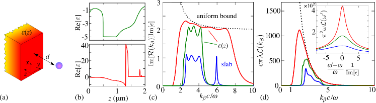
In this section, we study RHT between an inhomogeneous slab and a dipole, depicted in Fig. 2(a). Beginning with a brief overview of the formulation, we establish an approximate bound for RHT in the case of semi-infinite, homogeneous bodies and exploit optimization to show that multilayer structures can come close to approaching these limits over a broad range of wavevectors, leading to orders-of-magnitude larger RHT. Our work extends recent studies of near-field RHT between dipoles and HMMs or thin films miller2014effectiveness to the mid-field regime.
Consider a small sphere of radius , approximated as a dipolar particle of polarizability , being its distance from a planar substrate [see Fig. 2(a)]. In what follows, we focus on the off-resonance regime , in which the spectral transfer rate reads , where denotes the Green’s function of the slab at the position of the dipole volokitin2007near . At short separations , the relevant tensor components of the Green’s functions are:
| (7) |
with the reflection coefficient of the slab obtained again by solving Eq. (1). Note that by Poynting’s theorem, the RHT rate is proportional to the LDOS at the position of the dipole, , except in the regime where the latter overestimates RHT since it also captures power radiating into the vacuum region oskooi2013electromagnetic .
First, as in the plate–plate scenario, we investigate the possible enhancements in or that can arise from a spatially varying dielectric profile. Unlike the previous scenario, where was a highly non-monotonic function of , here the RHT integrand is linearly proportional to . Assuming small losses and defining , a useful figure of merit is the maximum and optimal permittivity of a uniform, semi-infinite slab at any given :
| (8) | |||
| (9) |
Both quantities are strongly divergent at , suggesting that the monochromatic LDOS of an inhomogeneous slab can in principle be unbounded, with the main contribution to the divergence coming from wavevectors near the light cone . We first observe that such a divergence would theoretically persist for any distance , since the separation enters (7) only as a parameter through the exponential factors. However, (9) shows that at least for a uniform medium, maximizing in the limit requires a perfect metal (), which can be shown to screen the response at other , resulting in a vanishing bandwidth and . Consequently, the integrated response of a uniform slab is finite and maximized by a finite thickness and permittivity, which can be found numerically. More significant improvements, however, can be gained from a spatially varying , which provides additional degrees of freedom with which to simultaneously tune the scattering rate at different , allowing the response to approach the bounds described by (8) over wider bandwidths. Realizing such an enhancement presents, however, both conceptual and numerical challenges: waves approaching the light line have increasingly longer wavelength in the direction and are thus increasingly sensitive to spatial variations, requiring longer slabs and sharper variations in . Any numerical optimization strategy will thus benefit only from finite enhancements coming from due to the finite number of layers needed to resolve . One should also consider that, as shown above, in the simple case of a uniform slab the permittivity that maximizes the LDOS at equals -1, while (9) requires as . In practice, the optimal profile results from a tradeoff between these two conditions, since very high values of act to screen the response from other regions of the slab. Such distinct and challenging requirements make the optimization procedure highly nontrivial, increasing the computational cost of RHT calculations and slowing the convergence rate of the optimization algorithm, which can get easily trapped in multiple local optima. To illustrate these features, we perform separate optimizations with different constraints on the maximum allowed permittivity , which limits potential enhancements coming from waves near the light line.
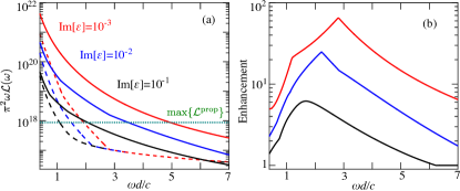
Figure 2 reports optimizations of the evanescent contribution to at a vacuum wavelength m and for m. Figure 2(b) shows representative profiles obtained under different and at fixed . Noticeably, the lower profile exhibits rapid, subwavelength variations over small (tens to hundreds of nanometers) regions: as discussed earlier, these are needed to maximize near while avoiding screening effects at larger , with higher occurring away from the interface for the same reason. This explains why larger lead to greater enhancements, illustrated in Figs. 2(c) and (d), which show and as a function of . The results, which are also compared against those of uniform slabs of optimal thickness and permittivity (blue line), reveal that inhomogeneous structures can approach the bounds described by (8) (dashed black line) over much broader range of . Although producing a significant increase with respect to uniform slabs, the optimization fails as due to the practical limitations discussed above. Moreover, these enhancements will necessarily come at the expense of increased frequency selectivity, since waves near the light line are most sensitive to deviations in the long-range spatial pattern of the structure, here optimized to realize a specific interference pattern at . This feature is apparent from the inset of Fig. 2(d), which shows the spectra of the optimized uniform and inhomogeneous slabs from above (neglecting material dispersion): namely, the contribution of lower states becomes increasingly restricted to frequencies as . (Note that the factor of in the abscissa is there because just as in the case of a uniform medium, the bandwidth of the Lorentzian-like spectrum is proportional to the loss rate.)
We now explore the enhancement factor from optimized inhomogeneous slabs for a wide range of separations m. To begin with, Fig. 3(a) shows the maximum LDOS of the optimized inhomogeneous (solid lines) and uniform (dashed lines) slabs, as a function of and for multiple values of (red, blue, and black lines respectively), with their ratio, the enhancement factor, depicted in Fig. 3(b). As shown, in both situations the LDOS increases rapidly with decreasing and decreasing material losses. In particular, the enhancement factor [in principle infinite for any , as suggested by (8)] increases up to a maximum value (dictated by the smallest participating, enhanced wavevector) and then decreases, approaching 1 as . Essentially, at large , the evanescent LDOS becomes increasingly dominated by wavevectors close to the light line (for which the optimization procedure fails). Consequently, beyond some separation the propagating contributions to dominate. Such finite enhancements also imply that at small , where the LDOS becomes increasingly dominated by large waves, the optimal slab is one satisfying the typical resonant condition of and hence the enhancement factor approaches 1.
For comparison, the green dotted line in Fig. 3(a) denotes the largest achievable far-field LDOS in planar media,
| (10) |
derived by summing the propagative contributions under rate-matched reflection and energy conservation, , in which case . More precisely, the limit (10) can be derived by observing that for the polarization,
| (11) |
with the maximum achieved for structures with () at (); a similar bound applies to the polarization, leading to (10). Since it is derived under the assumption of an integrand maximized for any , provides an upper bound that is challenging to realize. However, as shown in Fig. 3, it is still smaller than the evanescent part of the LDOS for optimized inhomogeneous slabs over a wide range of separations. In particular, we remark that at the separations where the enhancement factor peaks, the evanescent contribution to the LDOS of the optimized homogeneous slabs is more than an order of magnutude larger than .
We remark that in the scenario of inhomogenous slabs, the LDOS decreases smoothly with increasing separation and material loss, while in the case of optimal uniform slabs, material losses become irrelevant at distances . In order to explain this feature, we observe that for for (red and blue lines respectively), the first-order derivative of the peak LDOS for uniform slabs is a discontinuous function of separation at a given , depending on . This results from an abrupt transition between two mechanisms of enhancement. In particular, depending on the separation, the uniform slab either maximizes the LDOS at some intermediate through a resonant (small ) or near with (large ). In the latter case, the imaginary part of the permittivity becomes irrelevant.
Since LDOS enhancements from inhomogeneous slabs prove significant at mid-range separations, one may wonder whether similar enhancements can be achieved in previously studied planar geometries. One such geometry are HMMs, which consist of alternating metal and dielectric layers and are known to exhibit hyperbolic dispersion guo2012broadband ; BiehsAPL13 . While it has been demonstrated that RHT between a dipole and a HMM in the deep near field is no larger than that of an appropriately designed uniform thin film miller2014effectiveness , we analyze below whether this remains true in the mid-field regime. Consider for instance, a HMM of period described as an effective, uniform anisotropic medium, with permittivities (surface-parallel) and (surface-perpendicular), having real parts and respectively, and by assumption the same small imaginary part . The hyperbolic regions of the spectrum are those in which , i.e. when the real parts have opposite signs. More specifically, one typically defines two categories of HMMs: type I with and , and type II with and . While in the extreme near-field there is no distinction between the two types, given that only the product matters guo2012broadband , the two exhibit very different behavior in the mid-field. Focusing on the dominant, polarization (), the relevant quantity in type-I HMMs is
| (12) |
which is clearly far smaller than that of uniform isotropic slabs (scaling as ), resulting in much smaller RHT in the limit of small . The behavior of type-II HMMs, on the other hand, varies depending on two different regimes: , in which case , and (requiring ), in which case the peak
| (13) |
occurs at . Note that similar to the case of isotropic slabs, as and . However, as before, such a large dielectric constant results in a significant screening effect and thus narrow bandwidth, whose full width at half maximum . In the limit of a diverging permittivity, faster than diverges, leading to vanishing RHT. Hence, one finds once again that HMMs are in principle not better than uniform, isotropic thin films at mid-field separations and are therefore never “discovered” by the optimization method.
V Concluding Remarks
We have studied optimization of frequency-selective near-field radiative heat transfer between either two slabs or between a dipolar particle and a slab, allowing inhomogenous dielectric profiles along the symmetry axis of the slabs. Our approach relied on application of large-scale, gradient-based optimization, which allows dealing with a large number of degrees of freedom, in combination with a simple-to-evaluate differential equation describing the reflectivity of a planar substrate of varying . In the plate-plate scenario, we extended previous theoretical bounds derived for homogeneous planar structures miller2015shape and showed that inhomogeneous dielectric profiles enable rate matching (perfect absorption) of waves over a wide range of wavevectors, limited only by material loss rates. In spite of nearly perfect coupling, we find relatively low enhancement factors due to the logarithmic dependence of the amplification on material losses. Nevertheless, we observe that the plate–plate optimization is robust up to single-layer thicknesses of the order of tens of nanometers and with respect to frequency, making these predictions in principle experimentally feasible albeit challenging to test, e.g. by employing molecular beam epitaxy with vertically varying doping concentration and hence dielectric properties.
We found, however, that much larger enhancements can be achieved in the dipole–plate scenario, where RHT is proportional to the LDOS. While the LDOS in this configuration is in principle unbounded, we find that any RHT enhancement is in practice limited by a challenging and seemingly prohibitive compromise requiring perfect-metal behavior to increase the flux at small wavevectors (approaching the light line) and resonant, negative permittivities () needed at larger wavevectors. Our optimization procedure was able to discover profiles able to partially satisfy these two criteria and hence achieve large near-field absorption over a wide range of wavevectors, leading to enhancement factors of up to two orders of magnitude at mid-range separations, limited only by the finite discretization and size of the multilayer structure as well as the existence of multiple local minima. As explained, because the source of the enhancement is increased absorption from waves near the light line, such increased RHT in the dipole–plate configuration necessarily comes at the expenses of increased frequency selectiviy and lack of robustness, depending sensitively on the precise dielectric arrangement and choice of wavelength. Nevertheless, our numerical experiments provide a proof of principle that multilayer structures can overcome the wavevector–bandwidth limitations of uniform slabs in the near field, allowing the wavevector and spectral response of planar materials to be tailored.
Acknowledgements
This work was supported by the National Science Foundation under Grant no. DMR-1454836 and by the Princeton Center for Complex Materials, a MRSEC supported by NSF Grant DMR 1420541.
References
- (1) S. Basu, Z. Zhang, and C. Fu, “Review of near-field thermal radiation and its application to energy conversion,” International Journal of Energy Research 33, 1203 (2009).
- (2) A. Volokitin and B. N. Persson, “Near-field radiative heat transfer and noncontact friction,” Rev. Mod. Phys. 79, 1291 (2007).
- (3) K. Joulain, J.-P. Mulet, F. Marquier, R. Carminati, and J.-J. Greffet, “Surface electromagnetic waves thermally excited: Radiative heat transfer, coherence properties and casimir forces revisited in the near field,” Surf. Sci. Rep. 57, 59 (2005).
- (4) C. R. Otey, L. Zhu, S. Sandhu, and S. Fan, “Fluctuational electrodynamics calculations of near-field heat transfer in non-planar geometries: A brief overview,” J. Quant. Spectrosc. Radiat. Transf. 132, 3 (2014).
- (5) X. Liu, L. Wang, and Z. M. Zhang, “Near-field thermal radiation: Recent progress and outlook,” Nanoscale and Microscale Thermophysical Engineering 19, 98 (2015).
- (6) O. D. Miller, S. G. Johnson, and A. W. Rodriguez, “Shape-independent limits to near-field radiative heat transfer,” Phys. Rev. Lett. 115, 204302 (2015).
- (7) W. Srituravanich, N. Fang, C. Sun, Q. Luo, and X. Zhang, “Plasmonic nanolithography,” Nano Lett. 54, 1085 (2004).
- (8) L. Wang, S. Basu, and Z. Zhang, “Direct and indirect methods for calculating thermal emission from layered structures with nonuniform temperatures,” Journal of Heat Transfer 133, 072701 (2011).
- (9) I. Celanovic, F. OSullivan, M. Ilak, J. Kassakian, and D. Perreault, “Design and optimization of one-dimensional photonic crystals for thermophotovoltaic applications,” Opt. Lett. 29, 863 (2004).
- (10) J. Drevillon and P. Ben-Abdallah, “Ab initio design of coherent thermal sources,” J. Appl. Phys. 102, 114305 (2007).
- (11) A. David, H. Benisty, and C. Weisbuch, “Optimization of light-diffracting photonic-crystals for high extraction efficiency leds,” Journal of Display Technology 3, 133 (2007).
- (12) M. Ghebrebrhan, P. Bermel, Y. Avniel, J. D. Joannopoulos, and S. G. Johnson, “Global optimization of silicon photovoltaic cell front coatings,” Opt. Express 17, 7505 (2009).
- (13) N. P. Sergeant, O. Pincon, M. Agrawal, and P. Peumans, “Design of wide-angle solar-selective absorbers using aperiodic metal-dielectric stacks,” Opt. Express 17, 22800 (2009).
- (14) Y.-B. Chen and K.-H. Tan, “The profile optimization of periodic nano-structures for wavelength-selective thermophotovoltaic emitters,” International Journal of Heat and Mass Transfer 53, 5542 (2010).
- (15) S. Chen, H. Cheng, H. Yang, J. Li, X. Duan, C. Gu, and J. Tian, “Polarization insensitive and omnidirectional broadband near perfect planar metamaterial absorber in the near infrared regime,” Appl. Phys. Lett. 99, 253104 (2011).
- (16) E. Nefzaoui, J. Drevillon, and K. Joulain, “Selective emitters design and optimization for thermophotovoltaic applications,” J. Appl. Phys. 11, 084316 (2012).
- (17) K. X. Wang, Z. Yu, V. Liu, Y. Cui, and S. Fan, “Absorption enhancement in ultrathin crystalline silicon solar cells with antireflection and light-trapping nanocone gratings,” Nano Lett. 12, 1616 (2012).
- (18) C. Simovski, S. Maslovski, I. Nefedov, and S. Tretyakov, “Optimization of radiative heat transfer in hyperbolic metamaterials for thermophotovoltaic applications,” Opt. Express 21, 14988 (2013).
- (19) P. Wang and R. Menon, “Optimization of generalized dielectric nanostructures for enhanced light trapping in thin-film photovoltaics via boosting the local density of optical states,” Opt. Express 22, A99 (2013).
- (20) P. D. Anderson and M. L. Povinelli, “Optimized emission in nanorod arrays through quasi-aperiodic inverse design,” Opt. Lett. 40, 2672 (2015).
- (21) J. S. Jensen and O. Sigmund, “Topology optimization for nano-photonics,” Laser Photonics Rev. 5, 308 (2011).
- (22) V. Ganapati, O. D. Miller, and E. Yablonovitch, “Light trapping textures designed by electromagnetic optimization for subwavelength thick solar cells,” IEEE Journal of Photovoltaics 4, 175 (2014).
- (23) O. Ilic, P. Bermel, G. Chen, J. D. Joannopoulos, I. Celanovic, and M. Soljačić, “Tailoring high-temperature radiation and the resurrection of the incandescent source,” Nat. Nanotech. 11, 320 (2016).
- (24) P. I. Borel, A. Harpoth, L. H. Frandsen, M. Kristensen, P. Shi, J. S. Jensen, and O. Sigmund, “Topology optimization and fabrication of photonic crystal structures,” Opt. Express 12, 1996 (2004).
- (25) P. Bermel, W. Ghebrebrhan, M. Chan, Y. X. Yeng, M. Araghchini, R. Hamam, C. H. Marton, K. F. Jensen, M. Soljačić, J. D. Joannopoulos, S. G. Johnson, and I. Celanovic, “Design and global optimization of high-efficiency thermophotovoltaic systems,” Opt. Express 18, A314 (2010).
- (26) S.-A. Biehs, “Thermal heat radiation, near-field energy density and near-field radiative heat transfer of coated materials,” Eur. Phys. J. B 58, 423 (2007).
- (27) P. Ben-Abdallah, K. Joulain, J. Drevillon, and G. Domingues, “Near-field heat transfer mediated by surface wave hybridization between two films,” J. Appl. Phys. 106, 044306 (2009).
- (28) S. Basu and M. Francoeur, “Maximum near-field radiative heat transfer between thin films,” Appl. Phys. Lett. 98, 243120 (2011).
- (29) S. V. Boriskina, J. K. Tong, Y. Huang, J. Zhou, V. Chiloyan, and G. Chen, “Enhancement and tunability of near-field radiative heat transfer mediated by surface plasmon polaritons in thin plasmonic films,” in “Photonics,” , vol. 2 (Multidisciplinary Digital Publishing Institute, 2015), vol. 2, p. 659.
- (30) X. J. Wang, S. Basu, and Z. M. Zhang, “Parametric optimization of dielectric functions for maximizing nanoscale radiative transfer,” J. Phys. D: Appl. Phys. 42, 245403 (2009).
- (31) Y. Zhao, G. H. Tang, and Z. Y. Li, “Parametric investigation for suppressing near-field thermal radiation between two spherical nanoparticles,” International Communications in Heat and Mass Transfer 39, 918 (2012).
- (32) E. Nefzaoui, Y. Ezzahri, J. Drevillon, and K. Joulain, “Maximal near-field radiative heat transfer between two plates,” Eur. Phys. J. Appl. Phys. 63, 30902 (2013).
- (33) E. Rousseau, M. Laroche, and J.-J. Greffet, “Radiative heat transfer at nanoscale mediated by surface plasmons for highly doped silicon,” Appl. Phys. Lett. 95, 231913 (2009).
- (34) S. Basu, B. J. Lee, and Z. M. Zhang, “Near-field radiation calculated with an improved dielectric function model for doped silicon,” J. Heat Transfer 132, 023302 (2010).
- (35) X. L. Liu and Z. M. Zhang, “Graphene-assisted near-field radiative heat transfer between corrugated polar materials,” Appl. Phys. Lett. 104, 251911 (2014).
- (36) C. Fu and Z. Zhang, “Nanoscale radiation heat transfer for silicon at different doping levels,” International Journal of Heat and Mass Transfer 49, 1703 (2006).
- (37) X. Liu, B. Zhao, and Z. M. Zhang, “Enhanced near-field thermal radiation and reduced casimir stiction between doped-si gratings,” Phys. Rev. A 91, 062510 (2015).
- (38) R. Guérout, J. Lussange, F. S. S. Rosa, J.-P. Hugonin, D. A. R. Dalvit, J.-J. Greffet, A. Lambrecht, and S. Reynaud, “Enhanced near-field thermal radiation and reduced casimir stiction between doped-si gratings,” Phys. Rev. B 85, 180301 (2012).
- (39) J. Dai, S. A. Dyakov, and M. Yan, “Enhanced near-field radiative heat transfer between corrugated metal plates: Role of spoof surface plasmon polaritons,” Phys. Rev. B 92, 035419 (2015).
- (40) J. Dai, S. A. Dyakov, and M. Yan, “Radiative heat transfer between two dielectric-filled metal gratings,” Phys. Rev. B 93, 155403 (2016).
- (41) J. Dai, S. A. Dyakov, S. I. Bozhevolnyi, and M. Yan, “Near-field radiative heat transfer between metasurfaces: A full-wave study based on two-dimensional grooved metal plates,” Phys. Rev. B 94, 125431 (2016).
- (42) Y. Yang and L. Wang, “Spectrally enhancing near-field radiative transfer between metallic gratings by exciting magnetic polaritons in nanometric vacuum gaps,” Phys. Rev. Lett. 117, 044301 (2016).
- (43) R. Messina, A. Noto, B. Guizal, and M. Antezza, “Radiative heat transfer between metallic gratings using adaptive spatial resolution,” Phys. Rev. B 95, 125404 (2017).
- (44) H. Chalabi, A. Alù, and M. L. Brongersma, “Focused thermal emission from a nanostructured sic surface,” Phys. Rev. B 94, 094307 (2016).
- (45) V. Fernández-Hurtado, F. J. Garcia-Vidal, S. Fan, and J. C. Cuevas, “Enhancing near-field radiative heat transfer with si-based metasurfaces,” arXiv preprint arXiv:1701.02986 (2017).
- (46) O. Ramezan Choubdar and M. Nikbakht, “Radiative heat transfer between nanoparticles: Shape dependence and three-body effect,” J. Appl. Phys. 120, 144303 (2016).
- (47) H. Chalabi, E. Hasman, and M. L. Brongersma, “Effect of shape in near-field thermal transfer for periodic structures,” Phys. Rev. B 91, 174304 (2015).
- (48) H. Chalabi, E. Hasman, and M. L. Brongersma, “Near-field radiative thermal transfer between a nanostructured periodic material and a planar substrate,” Phys. Rev. B 91, 014302 (2015).
- (49) S. Bhargava and E. Yablonovitch, “Lowering hamr near-field transducer temperature via inverse electromagnetic design,” IEEE Transactions on Magnetics 51, 3100407 (2015).
- (50) Y. Li, C. J. Zhang, T.-B. Wang, J.-T. Liu, T.-B. Yu, Q.-H. Liao, and N.-H. Liu, “Modulation of electromagnetic local density of states by coupling of surface phonon-polariton,” Mod. Phys. Lett. B 31, 1750050 (2017).
- (51) P. Ben-Abdallah, K. Joulain, J. Drevillon, and G. Domingues, “Tailoring the local density of states of nonradiative field at the surface of nanolayered materials,” Appl. Phys. Lett. 94, 153117 (2009).
- (52) O. D. Miller, A. G. Polimeridis, M. H. Reid, C. W. Hsu, B. G. DeLacy, J. D. Joannopoulos, M. Soljačić, and S. G. Johnson, “Fundamental limits to optical response in absorptive systems,” Opt. Express 24, 3329 (2016).
- (53) S. I. Maslovski, C. R. Simovski, and S. A. Tretyakov, “Overcoming black body radiation limit in free space: metamaterial superemitter,” New J. Phys. 18, 013034 (2016).
- (54) S. A. Ramakrishna, J. Pendry, M. Wiltshire, and W. Stewart, “Imaging the near field,” J. Mod. Opt. 50, 1419 (2003).
- (55) X. Zhang and Z. Liu, “Superlenses to overcome the diffraction limit,” Nat. Mater. 7, 435 (2008).
- (56) S.-A. Biehs and P. Ben-Abdallah, “Near-field heat transfer between multilayer hyperbolic metamaterials,” Z. Naturforsch. A 72, 115 (2017).
- (57) R. Messina and M. Antezza, “Scattering-matrix approach to casimir-lifshitz force and heat transfer out of thermal equilibrium between arbitrary bodies,” Phys. Rev. A 84, 042102 (2011).
- (58) R. Messina and M. Antezza, “Three-body radiative heat transfer and casimir-lifshitz force out of thermal equilibrium for arbitrary bodies,” Phys. Rev. A 89, 052104 (2014).
- (59) R. H. Byrd, J. Nocedal, and R. A. Waltz, “Knitro: An integrated package for nonlinear optimization,” in “Large-scale nonlinear optimization,” (Springer, 2006), p. 35.
- (60) C. Khandekar, W. Jin, O. D. Miller, A. Pick, and A. W. Rodriguez, “Giant frequency-selective near-field energy transfer in active–passive structures,” Phys. Rev. B 94, 115402 (2016).
- (61) S. Boyd and L. Vandenberghe, Convex optimization (Cambridge university press, 2004).
- (62) K. Svanberg, “A class of globally convergent optimization methods based on conservative convex separable approximations,” SIAM journal on optimization 12, 555 (2002).
- (63) J. Nocedal, “Updating quasi-newton matrices with limited storage,” Mathematics of computation 35, 773 (1980).
- (64) B. Liu and S. Shen, “Theory of the thermal radiation from optical antennas in far-and near-fields,” preprint arXiv:1509.00939 (2015).
- (65) L. Hu and S. Chui, “Characteristics of electromagnetic wave propagation in uniaxially anisotropic left-handed materials,” Phys. Rev. B 66, 085108 (2002).
- (66) M. Francoeur, S. Basu, and S. J. Petersen, “Electric and magnetic surface polariton mediated near-field radiative heat transfer between metamaterials made of silicon carbide particles,” Opt. Express 19, 18774 (2011).
- (67) O. D. Miller, S. G. Johnson, and A. W. Rodriguez, “Effectiveness of thin films in lieu of hyperbolic metamaterials in the near field,” Phys. Rev. Lett. 112, 157402 (2014).
- (68) A. Oskooi and S. G. Johnson, “Electromagnetic wave source conditions,” arXiv preprint arXiv:1301.5366 (2013).
- (69) Y. Guo, C. L. Cortes, S. Molesky, and Z. Jacob, “Broadband super-planckian thermal emission from hyperbolic metamaterials,” Appl. Phys. Lett. 101, 131106 (2012).
- (70) S.-A. Biehs, M. Tschikin, R. Messina, and P. Ben-Abdallah, “Super-planckian near-field thermal emission with phonon-polaritonic hyperbolic metamaterials,” Appl. Phys. Lett. 102, 131106 (2013).