Gyrator Operation Using Josephson Mixers
Abstract
Nonreciprocal microwave devices, such as circulators, are useful in routing quantum signals in quantum networks and protecting quantum systems against noise coming from the detection chain. However, commercial, cryogenic circulators, now in use, are unsuitable for scalable superconducting quantum architectures due to their appreciable size, loss, and inherent magnetic field. We report on the measurement of a key nonreciprocal element, i.e., the gyrator, which can be used to realize a circulator. Unlike state-of-the-art gyrators, which use a magneto-optic effect to induce a phase shift of between transmitted signals in opposite directions, our device uses the phase nonreciprocity of a Josephson-based three-wave-mixing device. By coupling two of these mixers and operating them in noiseless frequency-conversion mode, we show that the device acts as a nonreciprocal phase shifter whose phase shift is controlled by the phase difference of the microwave tones driving the mixers. Such a device could be used to realize a lossless, on-chip, superconducting circulator suitable for quantum-information-processing applications.
I Introduction
Performing high-fidelity, quantum nondemolition measurements in the microwave domain is an important requirement for operating a superconducting quantum computer. Such a requirement is enabled, in various schemes, by using nonreciprocal microwave devices having asymmetrical transmission through their ports, such as circulators Pozar ; Collin ; NoiselessCirc ; ReconfJJCircAmpl ; circulatorLehnert ; NRAumentado1 ; NRAumentado2 ; circulatorDiVincenzo1 ; circulatorDiVincenzo2 and low-noise, directional amplifiers ReconfJJCircAmpl ; DircJPC ; JDA ; JTWPA ; KIT ; TWPAthreewavemix . Circulators in particular play several crucial roles in these measurement schemes. They (1) allow quantum systems to be measured in reflection, (2) enable the use of reflective Josephson parametric amplifiers (JPAs) as a first-stage amplifier in the output chain, (3) protect quantum systems against noise in the measurement chain, such as amplified signals reflected off JPAs, excess backaction of directional amplifiers, strong microwave tones feeding JPAs, and noise coming from higher amplification stages of the output line. However, state-of-the-art commercial, cryogenic circulators, ubiquitously used throughout the field today, limit the maximum achievable measurement fidelity and scalability of quantum processors, due to their insertion loss dB, large size , and weight quinstar . They can also potentially negatively affect the coherence times of qubits, as they are comprised of bulk materials that thermalize poorly and employ strong inherent magnetic fields quinstar .
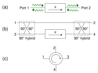
Nonreciprocal devices, which violate Lorentz reciprocity, break the invariance of the transmission parameter upon exchanging the source and detector Pozar ; Collin ; ReciprocityUnitarityTimeReversal . In this work, we demonstrate a successful operation of an important two-port, nonreciprocal circuit element, i.e., a gyrator, which can be used to build a circulator. A gyrator is a two-port, unity-transmission device, which introduces a differential phase shift of to microwave signals transversing the device in opposite directions Pozar ; Collin , as shown in Fig.1 (a). The scattering matrix of an ideal gyrator reads,
| (3) |
By incorporating an on-chip, lossless gyrator into one arm of a Mach-Zehnder interferometer, employing two hybrids Pozar , as shown in Fig. 1 (b), it is straightforward to obtain a four-port, on-chip, lossless circulator [Fig. 1 (c)] suitable for scalable quantum processors. In the circulator scheme shown in Fig. 1 (b), circulation is achieved via the generation of two-path interference for waves propagating through the device. The two-path interference is enabled by the addition of two hybrids, one on either side of the gyrator, which act as beam splitters for microwaves. For example, signals entering port 1 are fully transmitted to port 2 because half of the signal passing through the top arm of the interferometer constructively interferes with the other half of the signal passing through the gyrator incorporated into the bottom arm. On the other hand, signals entering port 2 would destructively (constructively) interfere on port 1 (3), resulting in isolation for port 1 and transmission to port 3.
In contrast to standard gyrator realizations, which utilize a magneto-optic Faraday effect in order to induce a nonreciprocal phase shift between microwave beams propagating in opposite directions, our scheme is based on a different physics. It utilizes the nonreciprocity of a photonic Aharonov-Bohm effect AhranovBohmPhotonic that is analogous to the original effect associated with charged particles AharonovBohm . While, in the electronic Aharonov-Bohm effect, electrons propagating in the presence of a magnetic vector potential acquire a nonreciprocal phase that depends on the direction of propagation, in the photonic counterpart, a nonreciprocal phase is acquired by photons propagating in the presence of an artificial gauge field. Such artificial gauge fields for photons can be generated by parametrically modulating certain properties of the photonic system, such as the dielectric constant of dielectric slab waveguides, which induce photonic transitions between two modes AhranovBohmPhotonic ; the resistance of microwave mixers, which convert the frequency of transmitted signals AhranovBohmMixers ; and the refractive index in rf-controlled phase modulators, which shift the phase of propagating optical signals nonreciprocityPhaseModulators . In general, the artificial gauge potential in such dynamical schemes corresponds to the modulation phase of the drive (pump). In our case, we generate a similar gauge field for propagating microwave signals by controlling the phase of a microwave drive, which parametrically modulates the dispersive inductive coupling between two nondegenerate resonance modes in dissipationless, three-wave mixers. As a result of this fundamental difference in the device physics, the main advantage of our proposed gyrator scheme over standard realizations is that it employs neither magnetic materials nor strong permanent magnets for its operation. Therefore, it can be low loss, integrated on chip, and fully compatible with superconducting circuits for extensible architectures.
While there have been numerous promising schemes which have been shown recently, either experimentally or theoretically, to perform a circulation operation suitable for quantum signals NoiselessCirc ; TRSbreakingInCQED ; ReconfJJCircAmpl ; circulatorLehnert ; NRAumentado1 ; NRAumentado2 ; circulatorDiVincenzo1 ; circulatorDiVincenzo2 , the main two differences between our proposed scheme and those relying on frequency conversion between three modes of a Josephson-based superconducting device, namely, Refs. ReconfJJCircAmpl and NRAumentado2 , are that our proposed circulator scheme preserves the frequency of the input and output quantum signals and requires, in principle, only one pump tone instead of three. This can result in a significant reduction in the overall control hardware resource for operating a larger number of devices. A more detailed comparison is presented in Sec. VII.
II The device
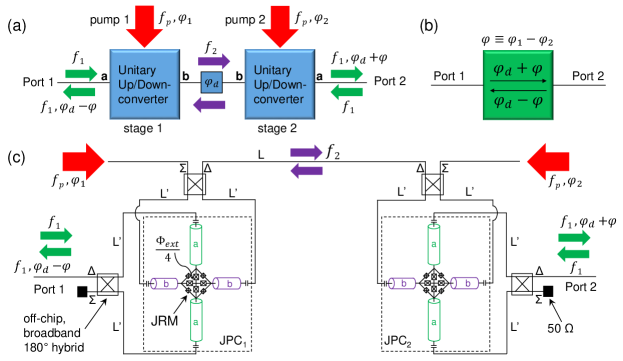
The nonreciprocal phase-shifter scheme, used to demonstrate a gyrator operation, employs two dissipationless, nondegenerate three-wave mixers. The general scheme for the two-port, nonreciprocal phase shifter is depicted in Fig. 2 (a). It consists of two unitary frequency-conversion stages (i.e., three-wave mixers) connected together by a transmission line. Incoming signals at frequency on port 1 (2) of the device are upconverted using the first (second) frequency-conversion stage to frequency () and transmitted via the transmission line to the second (first) frequency-conversion stage, where it is downconverted back to and exits through port 2 (1). Both frequency-conversion processes taking place in the device, i.e., upconversion and downconversion, are enabled via coherent energy exchange with the pump drives feeding the two mixing stages at a certain power, and whose frequency corresponds to the frequency difference . In addition to the critical role played by the pump power and frequency in the operation of the device, which will be made clear below, the pump phase plays a pivotal role as well. It controls the nonreciprocal phase shift experienced by the transmitted signals from port 1 to 2, i.e., , versus the phase shift acquired in the opposite direction, where is the phase difference between the two pump drives feeding the two mixing stages and is the phase shift introduced by the connecting components. Note that, since the nonreciprocal phase imprinted on the transmitted signals depends on the gradient of the pump phase, it does not depend on the gauge degree of freedom and thus it is gauge invariant AhranovBohmPhotonic . In Fig. 2 (b), we exhibit a black-box representation of the device, which emphasizes the nonreciprocal phase shift introduced by the device and its dependence on the phase difference between the two pump drives feeding the system. In Fig. 2 (c), we show in more detail how the proof-of-principle device is realized, i.e., by using two separate, nominally identical Josephson parametric converters (JPCs) JPCreview , connected through a (4”) coaxial line.
In general, JPCs are used as quantum-limited JPAs for qubit readout FluxoniumJumps ; FeedbackJPC , but they can also function as dissipationless three-wave mixers Conv ; QuantumNode . One main advantage of operating the JPC in the mixing mode for the gyration application instead of amplification is that, in the mixing mode, the frequencies of the transmitted signals through the device are converted without photon gain. As a result, the JPC is not required, according to Caves’ theorem Caves ; QuantumNoiseIntro to add any noise to the processed signals. As seen in Fig. 2 (c), the JPC comprises a Josephson ring modulator (JRM) embedded at the center of two orthogonal, half-wavelength microstrip resonators denoted as a and b. The JRM consists of four Josephson junctions (JJs) arranged in a Wheatstone-bridge configuration and functions as a nonlinear, dispersive mixing element. The resonators a and b support two microwave tones denoted as signal (S) (at frequency ) and idler (I) (at frequency ), respectively. These tones lie within the bandwidths and of resonators a and b, whose fundamental modes, at frequencies and , have an rf-current antinode at the JRM location. Both resonators are capacitively coupled to external feedlines that carry microwave signals into and out of the JPC. To address the a and b modes and apply the pump drive (P) to the device, both the S and I tones enter and exit through the delta ports of two off-chip, broadband hybrids (which define the S and I ports of the JPC), while the pump at is fed through the sigma port of the hybrid connected to port b (the other sigma port connected to port a is terminated by a Ohm cold load). Furthermore, to facilitate the mixing operation in the device, a dc circulating current is induced in the outer loop by an external magnetic flux threading the JRM JPCreview . The four large JJs inside the JRM loop serve as a linear shunt inductance for the outer JJs, which lifts the hysteretic response of the JRM versus flux and therefore makes the resonance frequencies of the JPC tunable Roch .
It is worth noting that the two resonance structures a and b, which incorporate the JRM at their center, play three important roles: (1) They set center frequencies and bandwidths for the two differential modes of the JRM, which, in turn, set the dynamical bandwidth of the device. (2) They increase the interaction time between the intraresonator photons taking part in the mixing operation and the JRM. (3) They inhibit the generation of harmonics or unwanted signals, as a result of the mixing process, whose frequencies do not lie within the bandwidths of the fundamental modes.
III Noiseless Frequency Conversion
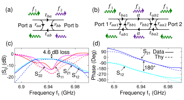
Figure 3 (a) shows a signal-flow graph for a JPC operated in frequency-conversion mode. In the stiff-pump approximation, the scattering parameters of the device read JPCreview
| (6) |
where () is the reflection parameter off port a (b), () is the transmission parameter from port a (b) to port b (a) with frequency upconversion (downconversion), and is a dimensionless pump amplitude. In Eq. (6), the are the bare response functions of modes a and b (whose inverses depend linearly on the S and I frequencies):
| (7) |
Since the applied pump frequency satisfies the relations , of Eq. (7) can be rewritten as . On resonance, the scattering parameters of Eq. (6) can be cast in the form
| (10) |
using the substitution relation tanh(i/2)=. The scattering parameters of Eqs. (6) and (10) embody five important properties that are crucial for understanding the device physics. They are as follows: (1) The scattering matrix is unitary (the total number of photons is conserved); i.e., the following relations hold, and . (2) The transmitted signals from port a to b (b to a) undergo frequency upconversion (downconversion). (3) On resonance () and for a sufficiently large pump drive , the reflections off the device ports vanish (), while the transmission with frequency conversion approaches unity (). 4) The phase of the transmitted signals depends on the phase of the pump drive [as seen in the expressions for and in Eq. (6)]. In general, this phase is gauge dependent since the time origin of the modulation can be ambiguous AhranovBohmPhotonic ; AhranovBohmMixers . However, in this experiment (as well as in other quantum-information-processing experiments in the microwave domain), the pump phase is well defined in reference to a common clock (i.e., the reference oscillator of a rubidium atomic clock), which phase locks all microwave sources and measurement devices. (5) The phase shift acquired by signals transversing the device is nonreciprocal (i.e., from port a to b and in the opposite direction).
IV Nonreciprocal phase shifter
The signal-flow graph for the two-stage JPC (TSJPC) device is shown in Fig. 3 (b). The scattering parameters in the graph with the subscript 1 (2) correspond to those of JPC 1 (2). The parameter incorporates the amplitude attenuation coefficient and the phase shift experienced by the idler signals propagating between the two JPC stages at frequency . In the expression for , represents the delay time, which can, in turn, be expressed as , where is the speed of light, and and are the effective electrical length and dielectric constant of the coaxial lines and hybrids connecting the two stages, respectively. By inspection, the scattering parameters of the two-port device can be written in the form Pozar
| (13) |
where () is the reflection parameter off port 1 (2), () is the transmission parameter from port 1 to 2 (2 to 1) (with frequency preservation). Similar to the case of one JPC, on resonance () and for a sufficiently large pump drive , the reflections off the device ports vanish (), while the transmission amplitude approaches the attenuation amplitude set by the losses in the connecting stages (). However, the phase acquired by the transmitted signals on resonance from port 1 to 2, i.e., can be different from the phase acquired in the opposite direction, i.e., . While the total phase shift in each direction depends on the value of and , the differential phase between the two directions depends only on , i.e., . Thus, by setting the pump phase difference to , the TSJPC device can serve as a gyrator, which introduces a differential phase of between signal beams propagating in opposite directions.
V Experimental results
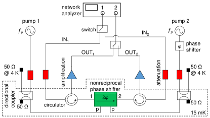
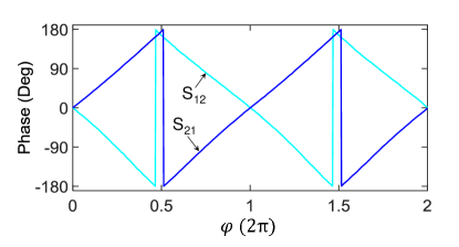
In Figs. 3 (c) and 3 (d), we demonstrate a gyrator operation using the TSJPC device. In Fig. 3 (c), we depict using solid lines a network-analyzer magnitude measurement of the scattering parameters of the TSJPC device taken versus input frequency . The resonance frequencies of resonators a of the two stages are flux tuned by about to coincide at , where is flux quantum. Both JPCs are operated in frequency-conversion mode with . The measurement of the four scattering parameters of the device is enabled by connecting each port of the device to separate input and output lines via a three-port cryogenic circulator as illustrated in Fig. 4. As expected, at resonance, the reflection parameters (red) and (magenta) exhibit a dip dB, while the transmission parameters (blue) and (cyan) exhibit a peak of about dB, which matches the insertion loss of the microwave components connecting the two stages at frequency , i.e., the normal-metal coaxial cables and hybrids. Further details regarding the in situ calibration of the amplitude of the scattering parameters are included in Appendix A. In Fig. 3 (d), we exhibit a phase-shift measurement of the transmitted signals (the solid blue line) and (solid cyan line), versus input frequency . The phase measurement is taken at the same working point as Fig. 3 (c). The phase difference between the pump drives feeding the two JPC stages is set to yield a relative phase shift of about between signals transmitted in opposite directions. The dashed lines in Figs. 3 (c) and 3 (d) exhibit a theoretical calculation for the scattering parameters of the device based on Eq. (13) and the device parameters, which yields a relatively good agreement with the data. It is interesting that the calculation reproduces multiple unintuitive features seen in the experiment [Fig. 3 (c)], such as bends and plateaus, which can be attributed to dispersion effects of the waves propagating in the connecting microwave components and to reflection effects, which result from a certain mismatch in the relatively narrow bandwidths of the two JPCs. We also measure, at this working point, the maximum input power above which the device starts to saturate (i.e., the transmission magnitude of the device drops by dB). We find it to be around dBm, which is comparable to the measured values in microstrip JPCs operated in frequency conversion Conv .
Furthermore, in Fig. 5, we display a phase-shift measurement of the transmitted signals through the device in opposite directions, taken on resonance as a function of the applied phase difference . As seen in the data, the phase shifts of and vary in opposite directions and depend linearly on , which fully agree with the theoretical prediction. This measurement result shows that the device can not only serve as a gyrator, but also as a general-purpose, nonreciprocal phase shifter, which can be fully and rapidly controlled in situ by a microwave signal, i.e., the pump. The upper limit on such fast control is mainly set by the dynamical bandwidth of the device.
We also verify in a separate measurement (not shown) that the device at the gyrator working point does not generate any undesired harmonics in response to an input at or cause any observable power leakage between ports a and b at the idler frequency . This is done by measuring the output signal of the device in a wideband frequency span , using a spectrum analyzer while inputting a signal at . However, in this measurement, we observe a certain power leakage at the pump frequency between ports a and b. This is likely the case because the pump frequency lies outside the band of the off-chip hybrids used for injecting the pumps to the device, which is . This undesired feature can be mitigated in the future by using hybrid-less JPCs in which the pump drive is injected through a separate physical port hybridLessJPC .
VI Circulator scheme
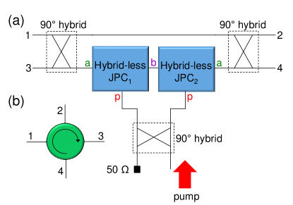
In Fig. 6 (a), we present a circuit diagram of our proposed circulator scheme. It consists of (1) two hybrid-less JPCs hybridLessJPC realized back to back on the same chip or in close proximity to each other (). By employing hybrid-less JPCs, which have separate physical ports for the pump drives, the four hybrids used in this work, as well as the intermediate components such as connectors and coaxial cables can be eliminated. Also, the footprint of JPCs can be significantly reduced by replacing the microstrip resonators with a lumped-element realization JPCreview ; LumpedJPC . (2) Two identical hybrids, which together with the TSJPC form a Mach-Zehnder interferometer, as illustrated in Fig. 6 (a). In this scheme, the TSJPC is incorporated into one arm of the interferometer and the hybrids have bandwidths that are centered around . (3) One hybrid, whose bandwidth is centered around , is used to deliver one pump tone to the two pump ports of the TSJPC. In addition to delivering an equal pump amplitude and frequency to the TSJPC, the hybrid plays another crucial role of satisfying the pump phase-gradient requirement needed for the operation of the JPC-based gyrator, namely, imposing a relative phase of between the pumps driving the two stages. The three hybrids can be implemented on chip using a coplanar waveguide geometry CPWhybrids or lumped elements Lumpedhybrids . Figure 6 (b) exhibits a circuit symbol for the circulator scheme introduced in Fig. 6 (a). Using this scheme, it is straightforward to design and implement circulators having center frequencies in the range , which matches the frequency range of working JPCs DircJPC ; JPCreview ; Conv ; LumpedJPC .
Since coplanar or lumped-element hybrids can have bandwidths in the range , the main bandwidth limitation of this scheme is set by the JPC bandwidth, which is on the order of JPCreview ; LumpedJPC . One possible method to significantly increase this bandwidth to several hundreds of megahertz entails making the following design changes to the JPC and its coupling to the feedlines: (1) implement lumped-element JPCs JPCreview ; LumpedJPC that are analogous to lumped-element JPAs, (2) provide a separate physical feedline for the pump drive that is distinct from the signal and idler feedlines hybridLessJPC , and (3) replace the coupling capacitors between the JPC and its signal and idler feedlines by series circuits, whose properties are outlined for the case of JPAs in Ref. JPAimpedanceEng .
Based on the viable assumptions that (1) lumped-element JPCs and coplanar-waveguide hybrids CPWhybrids can be compact and realized on chip, (2) the JRMs can be flux biased using on-chip flux lines, (3) the circulator chip is housed in a small, copper package, (4) the device ports consist of SMA connectors, and (5) a printed circuit board connects the SMA connectors and the circulator chip, we estimate the volume and the weight of our devices to be less than and , which are factors of and smaller than those of cryogenic, commercial circulators. Further reduction in size is possible by replacing the coplanar-waveguide hybrids with lumped-element versions Lumpedhybrids , increasing the pump frequency, and swapping the SMA connectors with a more miniature substitute.
It is important to point out that, despite these significant reductions in volume and weight, it is unlikely that, in scalable quantum architectures, these circulators would be used as stand-alone components. They are more likely to be integrated on chip or into a printed circuit board with other microwave components, which is, in turn, expected to reduce the number of connectors and yield a further reduction in size and weight.
Finally, one comment regarding the thermalization of the device: It is quite possible that, in a large quantum system, which utilizes many of these circulators, the heat generated by the pump power feeding these active circulators could exceed the cooling power of the mixing chamber. In that case, some of the reflected pump power could be routed and dissipated at higher-temperature stages (instead of the mixing chamber), which have larger cooling power, such as the still or the stage. While such an arrangement would effectively increase the footprint of the setup, it can be executed in a very efficient and compact manner by integrating arrays of circulators on the same chip or the same printed circuit board and combining the reflected pumps into a small set of lines.
VII Comparison with other circulator schemes
As outlined in the Introduction, several on-chip circulator schemes have been proposed recently and numerous proof-of-principle circulators have been demonstrated. In this section, we focus our discussion on three schemes, which share certain common features with our proposal. The first is the theoretical circulator scheme presented by Kamal et al. NoiselessCirc . The second and the third are the experimental works by Sliwa et al. ReconfJJCircAmpl and Lecocq et al. NRAumentado2 , which demonstrate circulation using Josephson devices.
The main two similarities between our circulator scheme and the one proposed in Ref. NoiselessCirc are that both rely on two-stage, active, upconverter and downconverter Josephson devices to generate a nonreciprocal response for microwave signals, and they both break reciprocity by applying a gradient of the pump phase between the two stages (which is analogous to the role played by the magnetic field in a Faraday medium). On the other hand, the two schemes have several important differences: (1) The theoretical scheme of Ref. NoiselessCirc is applicable to a broad group of parametric active devices. However, in practice, if realized using JPCs, it is expected to handle relatively low frequency signals ( ). Our scheme, on the other hand, would enable circulation for microwave signals in the gigahertz range. (2) The pump frequency in Ref. NoiselessCirc plays the role of a carrier frequency, which is modulated by the signal frequency, which in turn produces two idler frequencies. In our device, by contrast, the signal is upconverted to a single idler frequency using a pump at the frequency difference. (3) The scheme of Ref. NoiselessCirc involves amplification and deamplification of signals. In our case, no amplification or deamplification is applied by the active devices. (4) The scheme of Ref. NoiselessCirc requires a phase shifter between the two stages, which is not necessary in our device.
With regard to the circulator schemes of Refs. ReconfJJCircAmpl and NRAumentado2 , the physical mechanism for generating nonreciprocity is very similar to the one utilized here. They both rely on parametric frequency-conversion processes taking place between three resonant modes of the respective Josephson devices. Both schemes also use the relative phase of the pumps driving the Josephson devices in order to induce nonreciprocal response, i.e., circulation. The main two differences, however, between our scheme and those of Refs. ReconfJJCircAmpl ; NRAumentado2 lie in the devised coupling between the three modes and how wave interference is generated. While the schemes of Refs. ReconfJJCircAmpl ; NRAumentado2 employ three distinct-frequency resonance modes of the same Josephson device, ours employs two identical pairs of resonance modes existing in two separate Josephson devices (each having modes a and b), in which one pair with the same frequency (e.g., two b modes) are coupled together, thus serving as an internal mode of the system. Also, while the schemes of Refs. ReconfJJCircAmpl ; NRAumentado2 interfere with frequency-converted signals internally, inside the Josephson device, our scheme generates interference externally, using the Mach-Zehnder interferometer.
Some potential advantages of our proposed circulator scheme over the circulators presented in Refs. ReconfJJCircAmpl ; NRAumentado2 include the following:
(1) It realizes circulators with four ports versus three. The additional port can be used to enhance connectivity in quantum networks, reduce the total number of circulators in quantum processors, and improve thermal anchoring (e.g., by connecting one port of the circulator to a cold termination). As an example for enhanced connectivity using the four-port circulator, an input line is connected to port 1, a quantum-resonator system to port 2, a JPA (working in reflection) to port 3, and an output line to port 4.
(2) It preserves the frequency of the processed signal across all ports. This property can be useful, for example, in reducing the number of microwave generators required for qubit readout. In state-of-the-art qubit readout schemes, in which the frequency of the readout is preserved, one generator is sufficient. In such a setup, the output signal of the generator is split into two parts. The frequency of one portion, serving as the readout signal for the qubit-resonator system, is offset by tens of megahertz (e.g., ) using an in-phase quadrature mixer, which, in turn, is modulated by an arbitrary-wave-generator control signal. Such control signals are required in qubit measurements in order to orchestrate the timing, shape, and sequence of the various qubit and readout pulses. The other portion of the generator signal facilitates the downconversion of the gigahertz-range readout signal exiting the fridge down to a megahertz-range signal ( ) using a room-temperature mixer. It is this downconverted signal that is ultimately digitized and measured in the majority of qubit-readout experiments. However, when using a frequency-converting circulator for readout such as those in Refs. ReconfJJCircAmpl ; NRAumentado2 , two microwave generators would be necessary because the input and output readout signals are several gigahertz apart.
(3) It requires, for its operation, one pump tone versus three. This can result in a significant reduction by a factor of three in the number of microwave generators needed for the operation of superconducting circulators in large quantum networks.
(4) It has four degrees of freedom/control knobs needed for its operation (i.e., the fluxes threading the two JRMs, the amplitude and frequency of one microwave drive) versus seven (i.e., the flux threading the JRM/dc-SQUID, the amplitudes of the three pumps, the algebraic sum of their phases, and the frequencies of two out of the three pumps). Such a reduced number of degrees of freedom is expected to enhance the device stability over time and require simpler control and feedback schemes.
(5) It allows for a partial transmission of microwave signals between its ports, which the circulator is not specifically designed to block or route (e.g., out-of-band signals). This can be particularly useful when certain out-of-band signals serve only as inputs for a single-port quantum system. One example of such a scenario is a superconducting qubit dispersively coupled to a readout resonator measured in reflection. In this example, both the readout and qubit pulses, which can be a few gigahertz apart, can be applied to the narrowband circulator and feed the single-port qubit-resonator system connected to one port of the circulator. Assuming that the readout (qubit) signal of the qubit-resonator lies in band (out of band) of the circulator, the readout signal would be strictly routed between the circulator ports based on the circulation direction, while the qubit signal would reach all four ports equally.
VIII Summary
In this paper, we implement and measure a proof-of-principle, nonreciprocal phase shifter that does not employ any magnetic materials or strong magnets. The device is realized by coupling two dissipationless, nondegenerate Josephson mixers. By operating the Josephson mixers in frequency-conversion mode, we show that the phase shift acquired by signals transmitted through the device can be controlled in situ by the phase difference of the pump drives feeding the two mixers. We also show that by setting the phase difference of the pump drives to , the device can operate as a microwave gyrator. Both results are found to be in good agreement with the device theory.
Looking forward, the performance and size of such a nonreciprocal phase shifter can be significantly improved by eliminating the loss and delay between the two mixing stages. This can be achieved, for example, by integrating the two Josephson mixers on the same chip (or printed circuit board) in close proximity to each other and eliminating the need for bulky, off-chip, broadband hybrids by using a hybrid-less version of the Josephson mixers hybridLessJPC . Also, it is feasible to significantly enhance the instantaneous bandwidth of the device to more than by utilizing impedance-engineering techniques JPAimpedanceEng . Such a lossless, nonreciprocal phase shifter and gyrator, which does not employ any magnetic materials or strong magnets for its operation, could be used in a variety of quantum-information-processing applications. These applications could range from in situ manipulation of microwave signals in superconducting circuits to the realization of on-chip circulators for routing signals in a quantum processor.
Acknowledgements.
B.A. thanks Michel Devoret, Archana Kamal, and Michael Hatridge for discussions, and Christian Baks for the design and supply of printed circuit boards used in mounting the JPC devices.Appendix A In situ calibration of the device scattering parameters
In order to quantify the insertion loss of the intermediate stages that separate the two JPC stages, i.e., the two hybrids and coaxial cables [see Fig. 2 (c)], we utilize three properties of the JPC operated in conversion mode: (1) Without an applied pump, the JPC acts as a perfect mirror with unity reflection off the signal (a) and idler (b) ports. This can be verified by comparing the on-resonance and off-resonance reflection parameters of the JPC. In general, the off-resonance level of the reflection parameters of the JPC sets the dB reference for the scattering parameters measurement. (2) With an applied pump driving the JPC in full conversion, the amplitude of the transmission between the ports is unity. This can be inferred by measuring the reflection parameters on resonance which approach zero. (3) The amplitude of the transmission parameter is equal in both directions (i.e., from port a to b versus b to a). This property implies that, on resonance, the amplitudes of the transmission parameters through the whole device must be equal (since the hybrids and coaxial cables separating the two JPCs are passive and reciprocal). We also measure, using the setup exhibited in Fig. 4, the amplitude of the scattering parameters of the device, i.e., . Specifically, we measure the amplitude of the reflection parameters on resonance with no applied pump (the off state), and , and the amplitude of the transmission parameters on resonance with the TSJPC operated in full conversion (the on state), and .
To demonstrate how these measured parameters, combined with the JPC properties, can be used to determine the relative offset in decibels between the amplitude of the maximum transmission and the reflection parameters on resonance, we express them in the form
| (14) |
| (15) |
| (16) |
| (17) |
where () is the total attenuation in decibels of the input line that extends from port of the network analyzer to port () of the TSJPC at (see Fig. 4), () is the net gain in decibels of the output line that extends from port () of the TSJPC to port of the network analyzer at (see Fig. 4), is the insertion loss experienced by signals at that are either passing twice through the same hybrid and short, phase-matched coaxial cables connected to port a of the JPC [see Fig. 2 (c)] due to reflection or passing through two identical hybrids and short, phase-matched coax cables (connected to port a of the JPC) due to transmission through the TSJPC [see Fig. 2 (c)], and, finally, is the insertion loss in decibels of the intermediate stages in the TSJPC at [the two hybrids, the short, phase-matched coaxial cables, and the normal-metal coaxial cable connecting the two stages, as illustrated in Fig. 2 (c)].
One important observation from Eqs. (14)-(17) is that, although the hybrid and short, phase-matched coaxial-cables connected to port a are part of the JPC circuit, the insertion loss associated with them, , cannot be distinguished (through measurements of the scattering parameters of the device only) from and on port or and on port . In other words, can be lumped into and in a similar fashion to what is generally done for the loss associated with the circulators connected to the JPC ports, whose role is to separate the incoming and outgoing signals propagating on the JPC feedlines.
This is, however, not the case for the insertion loss associated with the intermediate components between the two stages . It can be evaluated by summing Eqs. (16) and (17) and substituting Eqs. (14) and (15) into the sum, which yields
| (18) |
In our case, we find that dB, which is consistent with room-temperature measurements of the intermediate components connecting the two JPCs taken at and below the loss limit of their specifications.
References
- (1) D. M. Pozar, Microwave Engineering, 3rd edition, (Wiley, Hoboken, NJ, 2005).
- (2) R. E. Collin, Foundations for Microwave Engineering, 2nd edition, (Wiley Interscience, Hoboken, NJ, 2014).
- (3) A. Kamal, J. Clarke, and M. Devoret, Noiseless non-reciprocity in a parametric active device, Nat. Phys. 7, 311 (2011).
- (4) K. Sliwa, M. Hatridge, A. Narla, S. Shankar, L. Frunzio, R. Schoelkopf, and M. Devoret, Reconfigurable Josephson Circulator/Directional Amplifier, Phys. Rev. X 5, 041020 (2015).
- (5) J. Kerckhoff, K. Lalumière, B. J. Chapman, A. Blais, and K. W. Lehnert, On-Chip Superconducting Microwave Circulator from Synthetic Rotation, Phys. Rev. Applied 4, 034002 (2015).
- (6) L. Ranzani and J. Aumentado, Graph-based analysis of nonreciprocity in coupled-mode systems, New J. of Phys. 17, 023024 (2015).
- (7) F. Lecocq, L. Ranzani, G. A. Peterson, K. Cicak, R. W. Simmonds, J. D. Teufel and J. Aumentado, Nonreciprocal Microwave Signal Processing with a Field-Programmable Josephson Amplifier, Phys. Rev. Applied 7, 024028 (2017).
- (8) G. Viola and D. P. DiVincenzo, Hall Effect Gyrators and Circulators, Phys. Rev. X 4, 021019 (2014).
- (9) S. Bosco, F. Haupt, and D. P. DiVincenzo, Self-Impedance-Matched Hall-Effect Gyrators and Circulators, Phys. Rev. Applied 7, 024030 (2017).
- (10) B. Abdo, K. Sliwa, L. Frunzio, and M. H. Devoret, Directional Amplification with a Josephson Circuit, Phys. Rev. X 3, 031001 (2013).
- (11) B. Abdo, K. Sliwa, S. Shankar, M. Hatridge, L. Frunzio, R. Schoelkopf, and M. Devoret, Josephson Directional Amplifier for Quantum Measurement of Superconducting Circuits, Phys. Rev. Lett. 112, 167701 (2014).
- (12) C. Macklin, K. O’Brien, D. Hover, M. E. Schwartz, V. Bolkhovsky, X. Zhang, W. D. Oliver, and I. Siddiqi, A near–quantum-limited Josephson traveling-wave parametric amplifier, Science 350, 307 (2015).
- (13) M. R. Vissers, R. P. Erickson, H.-S. Ku, Leila Vale, Xian Wu, G. C. Hilton, and D. P. Pappas, Low-noise kinetic inductance traveling-wave amplifier using three-wave mixing, Appl. Phys. Lett. 108, 012601 (2016).
- (14) A. B. Zorin, Josephson Traveling-Wave Parametric Amplifier with Three-Wave Mixing, Phys. Rev. Applied 6, 034006 (2016).
- (15) See http://pamtechinc.com
- (16) R. Carminati, J. J. Sáenz, J.-J. Greffet, and M. Nieto-Vesperinas, Reciprocity, unitarity, and time-reversal symmetry of the S matrix of fields containing evanescent components, Phys. Rev. A 62, 012712 (2000).
- (17) K. Fang, Z. Yu, and S. Fan, Photonic Aharonov-Bohm Effect Based on Dynamic Modulation, Phys. Rev. Lett. 108, 153901 (2012).
- (18) Y. Aharonov and D. Bohm, Significance of electromagnetic potentials in the quantum theory, Phys. Rev. 115, 485 (1959).
- (19) K. Fang, Z. Yu, and S. Fan, Experimental demonstration of a photonic Aharonov-Bohm effect at radio frequencies, Phys. Rev. B 87, 060301(R) (2013).
- (20) C. Galland, R. Ding, N. C. Harris, T. Baehr-Jones, and M. Hochberg, Broadband on-chip optical non-reciprocity using phase modulators, Opt. Express 21, 14500 (2013).
- (21) J. Koch, A. A. Houck, K. L. Hur, and S. M. Girvin, Time-reversal-symmetry breaking in circuit-QED-based photon lattices, Phys. Rev. A 82, 043811 (2010).
- (22) B. Abdo, A. Kamal, M. H. Devoret, Nondegenerate three-wave mixing with the Josephson ring modulator, Phys. Rev. B 87, 014508 (2013).
- (23) B. Abdo, J. M. Chavez-Garcia, M. Brink, G. Keefe, and J. M. Chow, Time-multiplexed amplification in a hybrid-less and coil-less Josephson parametric converter, Appl. Phys. Lett. 110, 082601 (2017).
- (24) U. Vool, I. Pop, K. Sliwa, B. Abdo, C. Wang, T. Brecht, Y. Y. Gao, S. Shankar, M. Hatridge, G. Catelani, M. Mirrahimi, L. Frunzio, R. Schoelkopf, L. Glazman, and M. Devoret, Non-Poissonian Quantum Jumps of a Fluxonium Qubit due to Quasiparticle Excitations, Phys. Rev. Lett. 113, 247001 (2014).
- (25) N. Ofek, A. Petrenko, R. Heeres, P. Reinhold, Z. Leghtas, B. Vlastakis, Y. Liu, L. Frunzio, S. Girvin, L. Jiang, M. Mirrahimi, M. Devoret, and R. Schoelkopf, Extending the lifetime of a quantum bit with error correction in superconducting circuits, Nature (London) 536, 441 (2016).
- (26) B. Abdo, K. Sliwa, F. Schackert, N. Bergeal, M. Hatridge, L. Frunzio, A. D. Stone, and M. Devoret, Full Coherent Frequency Conversion between Two Propagating Microwave Modes, Phys. Rev. Lett. 110, 173902 (2013).
- (27) E. Flurin, N. Roch, J. D. Pillet, F. Mallet, and B. Huard, Superconducting Quantum Node for Entanglement and Storage of Microwave Radiation, Phys. Rev. Lett. 114, 090503 (2015).
- (28) C. M. Caves, Quantum limits on noise in linear amplifiers, Phys. Rev. D 26, 1817 (1982).
- (29) A. A. Clerk, M. H. Devoret, S. M. Girvin, Florian Marquardt, and R. J. Schoelkopf, Introduction to quantum noise, measurement, and amplification, Rev. Mod. Phys. 82, 1155 (2010).
- (30) N. Roch, E. Flurin, F. Nguyen, P. Morfin, P. Campagne-Ibarcq, M. Devoret and B. Huard, Widely Tunable, Nondegenerate Three-Wave Mixing Microwave Device Operating near the Quantum Limit, Phys. Rev. Lett. 108, 147701 (2012).
- (31) J.-D. Pillet, E. Flurin, F. Mallet, and B. Huard, A compact design for the Josephson mixer: The lumped element circuit, Appl. Phys. Lett. 106, 222603 (2015).
- (32) H. S. Ku, F. Mallet, L. R. Vale, K. D. Irwin, S. E. Russek, G. C. Hilton, and K. W. Lehnert, Design and testing of superconducting microwave passive components for quantum information processing, IEEE Trans. Appl. Supercond. 21, 452 (2010).
- (33) L.-H. Lu, S. Mohammadi, G. E. Ponchak, P. Bhattacharya, and L. P. B. Katehi, Design and implementation of micromachined lumped quadrature () hybrids, IEEE MTT-S Int. Microwave Symp. Dig. 2, 1285 (2001).
- (34) T. Roy, S. Kundu, M. Chand, A. Vadiraj, A. Ranadive, N. Nehra, M. Patankar, J. Aumentado, A. Clerk, and R. Vijay, Broadband parametric amplification with impedance engineering: Beyond the gain-bandwidth product, Appl. Phys. Lett. 107, 262601 (2015).