Passive and active electromagnetic stabilization of free-surface liquid metal flows
Abstract
Free-surface liquid metal flows tend to be uneven due to instabilities and other effects. Some applications, however, require constant, uniform liquid metal thickness. This is for example the case of liquid walls in nuclear fusion reactors. With this motivation, here we present experimental results on the stabilization of a free-surface flow of Galinstan. The flow was sustained by an electromagnetic induction pump featuring rotating permanent magnets. Evidence is reported of the flowing Galinstan layer becoming flatter in the presence of a sufficiently strong magnetic field, either alone (passive stabilization) or in combination with an electrical current passing through the liquid metal (active stabilization). The results are interpreted in terms of an effective viscosity and effective gravity, respectively.
Introduction.
Free-surface flows of Lithium and other liquid metals are considered a promising plasma-facing “first wall” for a nuclear fusion reactor: liquid walls could protect the underlying solid walls from high heat and neutron fluxes [1, 2], and have been shown to lead to cleaner [3, 4, 5, 6] and more stable plasmas [7, 8].
However, free-surface liquid metal (LM) layers will tend to be uneven [9] as a result of non-uniform force fields, liquid metal instabilities and turbulence [10]. Uneven LM surfaces could enter in contact with the plasma, contaminate it, cool it, and possibly disrupt it, or they might expose the underlying solid wall to damage by heat and neutrons, and expose the plasma to a material with less benign erosion and wall recycling properties.
This motivated our investigation of how to stabilize free-surface liquid metal flows. As reported in the present article, this could be achieved “passively”, thanks to the strong magnetic field naturally present in a magnetically confined fusion reactor, or “actively”, by applying an electrical current in the liquid metal.
Note that, in addition to the deliberately applied current-pattern, other currents will naturally be induced in the liquid metal, e.g. due to rotating modes in the plasma, and additional current fluctuations could result from turbulence. These additional induced or fluctuating currents will be non-uniform and will change with time. As a result, the force-density will change, and adjustments of the applied current-pattern might be required, in feedback with multi-point measurements of liquid metal thickness. This is the subject of separate works [10, 11].
In this paper we start by discussing potential applications of stabilized, free-surface LM flows outside of fusion (Sec.1). In Sec.2 we describe the experimental setup, including the electromagnetic induction pump and a tiltable “tile” where the otherwise ducted flow is “free-surface” and exposed to a magnetic field , but not to a plasma, yet. Currents of density are also applied. Passive stabilization by only and active stabilization by are reported respectively in Sec.3 and 4, along with their interpretations.
1 Motivation: free-surface liquid metal flows.
Beside fusion-related uses, LM surface control has other scientific and industrial applications.
Controlling liquid metal flows can be of interest in metallurgy, for example to control a casting flow, to remove undesired droplets in laser- or plasma-cutting of metals or, on the contrary, to control and recover spills of precious materials, for economic reasons, or spills of toxic or unsafe materials, in order to protect public health and the environment.
Another area is furnaces. Conventional refractory materials are solid, but no solid material exists, at atmospheric pressure, above the melting point (4215 K) of Tantalum hafnium carbide. However, several metals (tantalum, tungsten, rhenium) are liquid in the 4200-6200 K temperature range. A good control of these metals in their liquid phase would allow coating the inner walls of a furnace and operating it at unprecedented temperatures. This would open the way to high-temperature chemistry in normally inaccessible regimes where certain undesired reactions are disfavored and certain elusive reactions are favored [12], from which new processes and materials could result.
At the opposite end of the spectrum of “heavy industry” are two emerging “high-tech” applications of LMs, which could benefit from passive, active or feedback stabilization. One technology is 3D metal printing [13]. The other makes use of Galinstan to realize flexible electronics, tunable metamaterials and microfluidic devices [13, 14, 15]. Both would benefit highly from flow control.
Finally, LMs are used to generate large concave reflective surfaces in some optical telescopes [16]: large containers filled with LMs rotate, and the LM surface assumes a paraboloidal shape as a result. Stabilization or, more generally, control, would “polish” the liquid mirror from small surface waves due to seismic vibrations. Furthermore, feedback control [10, 11] could pave the way to more advanced uses of LM surfaces, including adaptive optics. This could be extended to transparent conducting fluids for refractive optics: “liquid lenses” already exist [17], but they can only be adjusted in focal length. Also, they suffer from aberrations, which could be electromagnetically controlled.
2 Experimental setup: electromagnetic liquid metal pump and free-surface tile.
A Galinstan flow was sustained by an induction pump consisting of a ferromagnetic rotor with permanent magnets mounted on it [18]. The magnetic field is partly “frozen” in the liquid metal surrounding the rotor. Therefore, as the field rotates, the liquid metal rotates as well, although with a slip factor. This approach was preferred to conventional pumps, which would enter in electrical contact with the metal flow, and could be damaged by intense currents.
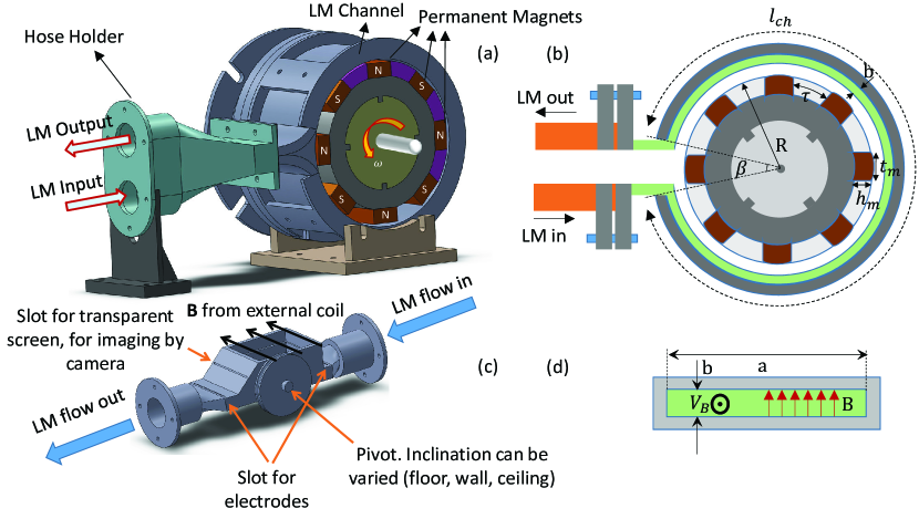
A schematic and two cross-sections of the pump are shown in Fig.1a, b and d. The dimensions are: rotor radius =9 cm, duct width =7 cm, height of liquid metal channel =3.5 mm, permanent magnets width and height, =2.54 cm and =1.27 cm, angle between inlet and outlet =30o.
The maximum pressure developed by the pump can be written as a function of the electrical conductivity , the slipping factor between the rotor velocity and fluid velocity , the magnetic field , mean length of the MHD channel and negative transverse-end effect coefficient [18]:
| (1) |
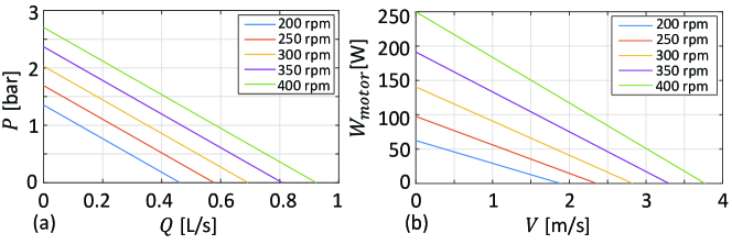
This pressure is plotted in Fig.2a as a function of the flow rate,
| (2) |
where and are the transverse sizes of the MHD channel in Fig.1d.
The product , where and are related to each other as in Fig.2a, represents the minimum motor power to rotate the rotor at a certain angular frequency . This estimate, however, neglects Ohmic losses in the LM,
| (3) |
The motor power needed can ultimately be calculated as .
Fig.2b illustrates the fluid velocities achievable by operating a motor of power at higher and higher . The initial prototype was nearly entirely realized in 3D-printed PLA plastic, to which Galinstan is not corrosive. With an electric 1 kW motor, it sustained Galinstan flows of up to 30 cm3/s.
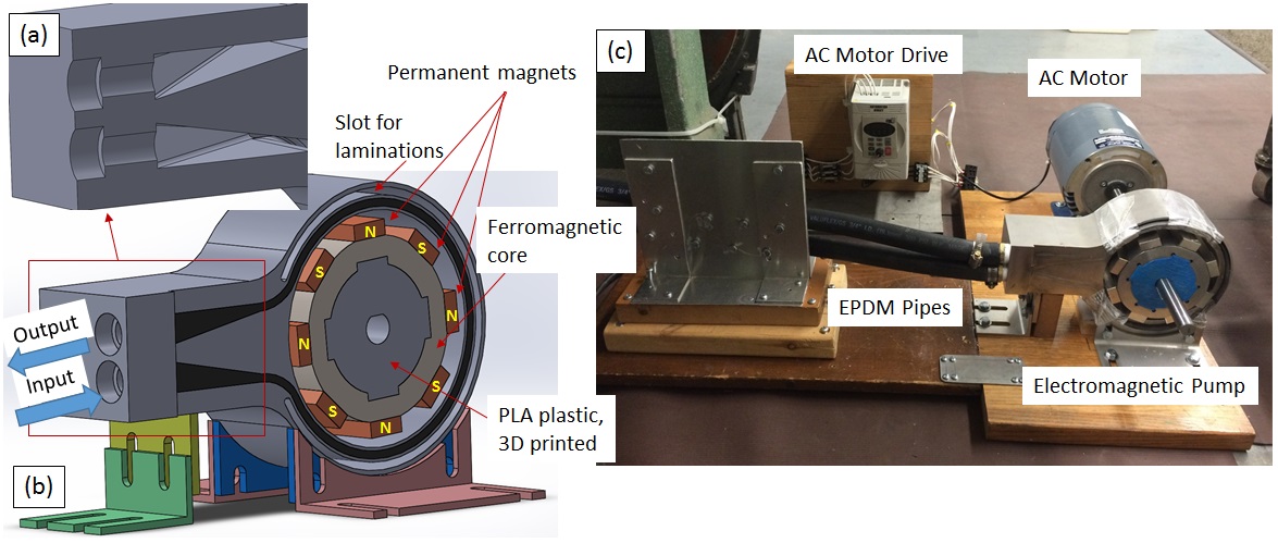
3D-printing was rapid and inexpensive. However, for increased mechanical strength, the pump was eventually rebuilt in non-magnetic stainless steel, with an improved design (Fig.3). We started with a single block with a large bore closely fitting to the rotor. Then, from one side of the block a Computer-Numeric-Control (CNC) machine excavated a duct of uniform cross-sectional area but variable cross-sectional shape. The shape varied from a 695 mm rectangle in proximity of the rotor, to take advantage of the strongest field, to 18.518.5 mm squares at the junctions with EPDM rubber hoses of circular cross-section. Finally, a CNC-machined lid (in black in Fig.3b) was welded on the block (in gray) to laterally seal the channel.
To increase and thus the pumping pressure , ferromagnetic laminations were inserted in dedicated slots in the stator, concentric to the duct, at slightly outer radii (Fig.3b). The lamination provided a low-reluctance path for the magnetic field lines through the MHD channel, which in turn increased proportionally to . The latter reduced the negative effect of losses due to eddy currents inside the body of the new metallic stator.
The hydraulic circuit was mostly ducted, but comprised a 3D-printed plastic, 510 cm tile (Fig.1c) for free-surface flows, which typically are 0.5-1 cm thick. The tile was tiltable to simulate the floor, wall or ceiling of a fusion reactor, and orientations in between.
2.1 Flow velocity calibration
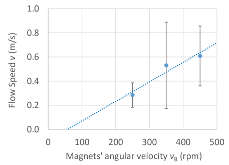
It was mentioned above that, due to the LM not being a perfect conductor, the field is not perfectly “frozen-in”, and the LM flow slips with respect to the rotor. For this reason, it was important to calibrate the flow velocity as a function of the rotor velocity . The flow velocity was measured by particle velocimetry, by means of fast-camera videos aquired at 2000 frames per second, and by means of photos of exposure time =0.5-2 ms. From the videos and photos it was possible to infer the speed of grains of dust and other natural impurities dragged by the LM, and assume that that was also the LM speed. The results of the calibration are summarized in Fig.4. The large error bars are due to measuring the non-uniform, time-evolving flow over several times and locations. On the other hand, the very fact that the flow is uneven and not constant makes it well-suited for stabilization experiments.
3 Passive electromagnetic stabilization.
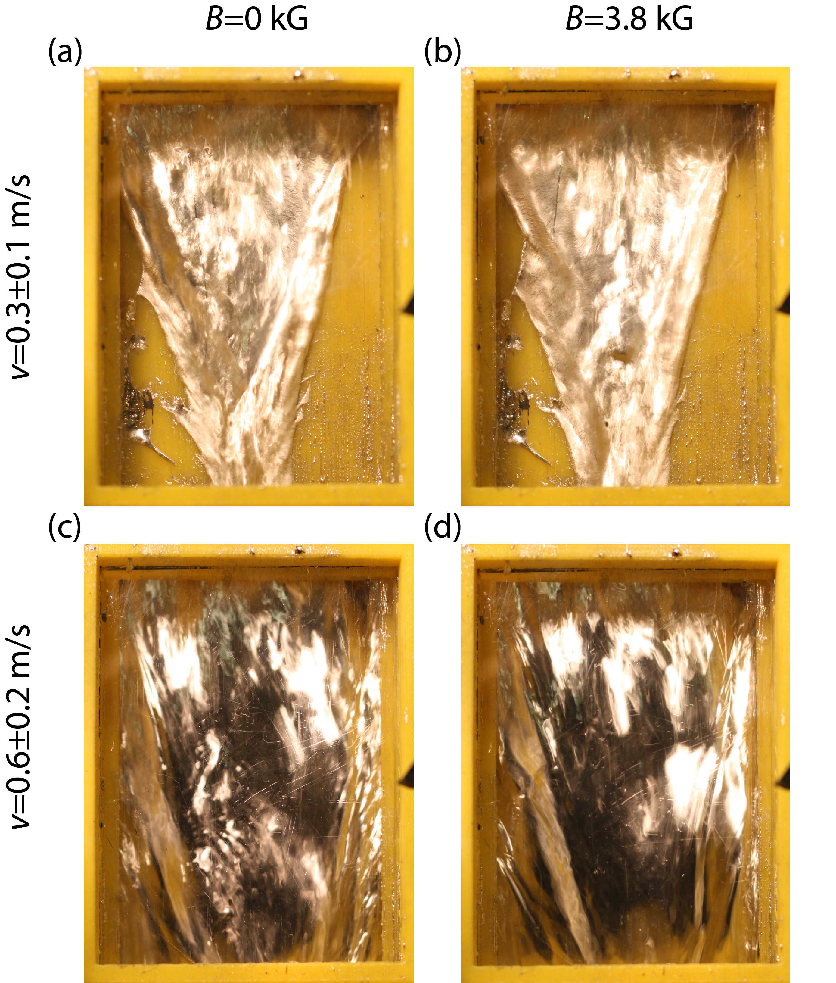
The tile shown in Fig.1c, with an approximately 5 mm thick layer of Galinstan flowing at velocity , was placed in a transverse magnetic field . A scan of up to 0.60.3 m/s and of up to 0.38 T provided the results shown in Fig.5. In the absence of magnetic field, small amplitude perturbations are visible over the surface of the flow. By applying the magnetic field, the velocity fluctuations are strongly damped.
3.1 Interpretation
The electromagnetic force term in the Navier-Stokes equation
| (4) |
contains, through the generalized Ohm’s law
| (5) |
a stabilizing term of order . This term dominates over the non-linear convective term , of order : the ratio of the two, for =0.4 T, =0.2 m/s, =0.1 and Galinstan conductivity and density, evaluates approximately 44.
In fact, the electromagnetic term also dominates over the viscous term : their ratio is the Hartmann number , which in the case of interest is of order 7104.
Therefore, in the limit of no applied electric field and negligible displacement current, the Navier-Stokes equation simplifies as follows:
| (6) |
That is to say that motion is governed by (basically, the pump), by gravity and by a term proportional to . The latter is clearly stabilizing: if we define the axis as the magnetic field direction, a fluctuation of velocity in the direction results in a current density fluctuation and hence in a force per unit volume . Note that this force is proportional to and opposite to it, hence it acts as a viscous drag. Also note that it scales like .
Similarly, in the direction . Furthermore, by incompressibility the volumetric strain rate evaluates . As a consequence, if and are kept small by stabilization, then is also small.
4 Active electromagnetic stabilization.
Flat electrodes described elsewhere [10] were used to apply currents longitudinal to the flow and thus apply jB forces orthogonal to the substrate.
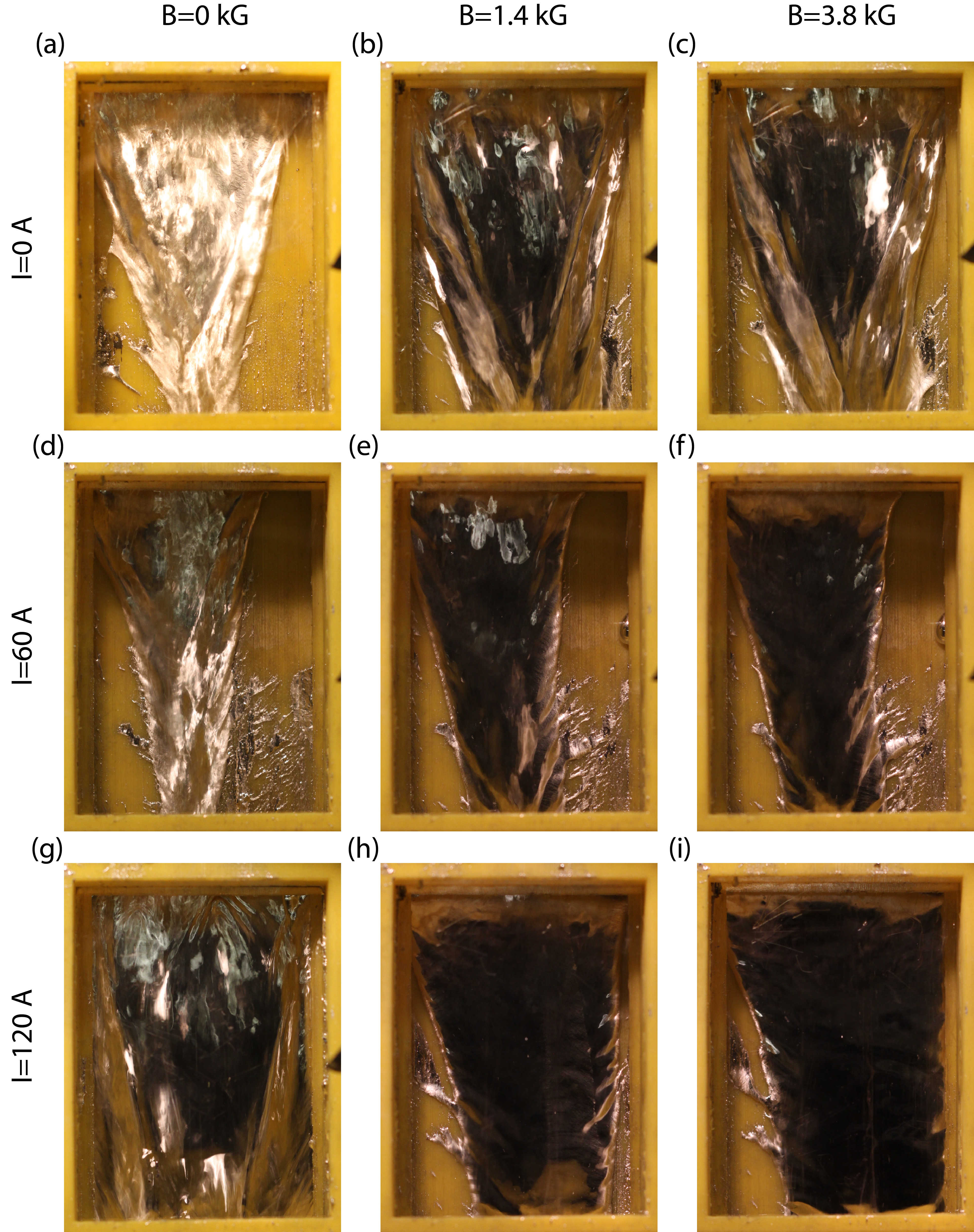
Fig. 6 presents qualitative results obtained with Galinstan flowing in the presence of =0.38 T and =0-120 A at 0.60.3 m/s. Shown are nine images of the 5 cm wide free-surface flow, acquired for increasing values of and .
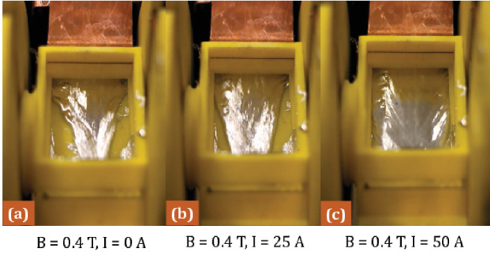
In the ducted part of the tile, the LM flow has rectangular cross-section. However, in the free-surface part of the tile, with the constraints of one wall now removed, the cross-section of the flow is free to change. Indeed, it does change in Fig.6, as a consequence of surface-tension trying to minimize the outer surface. In addition, gravity accelerates the flow and reduces its cross-section. In a reactor these effects would leave part of the solid wall and the plasma exposed to each other. It is reassuring, though, that when a sufficient Lorentz force is applied in the normal direction, the flow flattens and covers the tile nearly entirely (Fig.6i) or entirely (Fig.7c). Full-coverage depends on velocity and inclination, and can sometimes be obtained at reduced (Fig.7c).
In summary, a liquid metal flow in the presence of a DC magnetic field is stabilized if sufficiently intense transverse currents are applied.
4.1 Future work
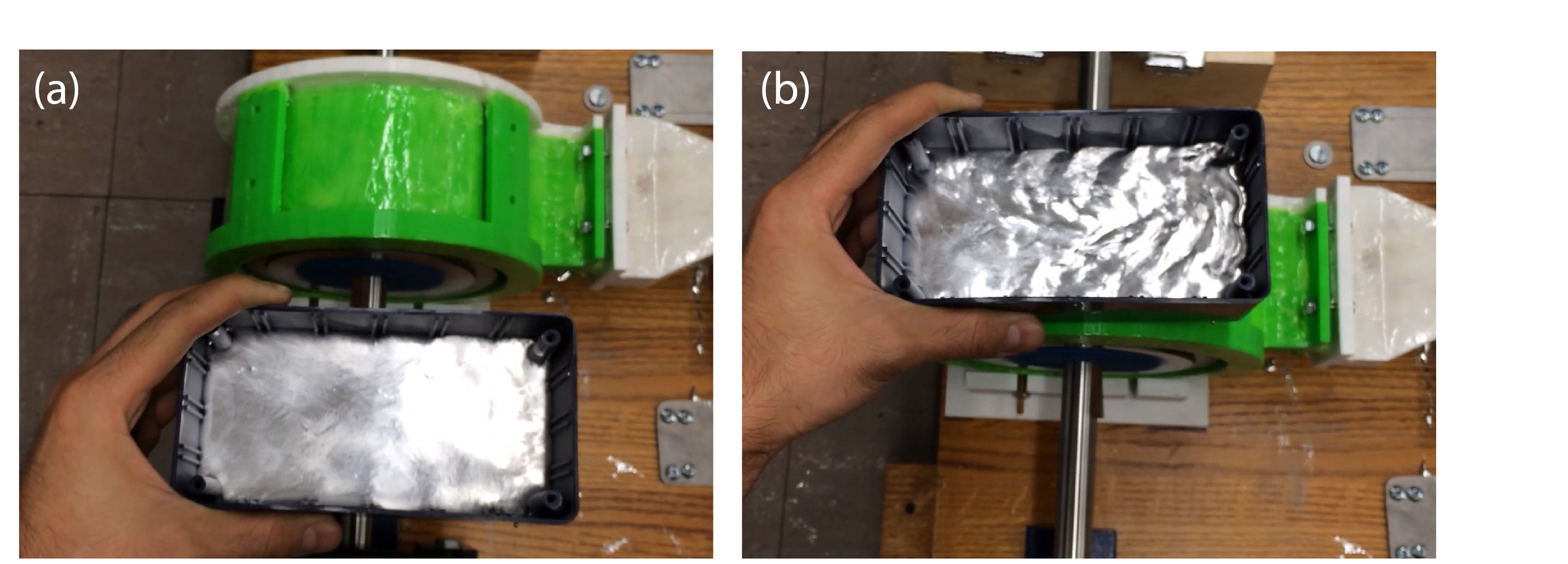
In addition to the applied and , undesired and are often present in the LM. The resulting undesired forces call for the need to adjust the applied in real time, in feedback with local LM thickness measurements [10, 11] . One such situation might occur when rotating instabilities -and the associated rotating helical field - are present in the plasma, inducing a helical in the LM. A toy model of this phenomenon is easily reproduced in the laboratory by means of the rotating permanent magnets featured in the pump (Fig.8).
A further motivation for feedback stems from the fact that the forces applied to the LM and pointing outward will never be perfectly uniform. The LM would thus be Rayleigh-Taylor unstable, similar to a pellet subject to inward-pointing forces in inertial confinement fusion [19].
Several other situations requiring feedback control were discussed in Ref.[10].
5 Summary and conclusions.
Results were presented about the electromagnetic stabilization of a free-surface flow of Galinstan. The flow was sustained by a rotating permanent magnet induction pump. Strong transverse magnetic fields were found to stabilize the flow. This was due to the velocity fluctuations perpendicular to causing a fluctuation of , through generalized Ohm’s law. The resulting force-density, scaling like , opposes the original velocity fluctuation. Parallel fluctuations are also small, as a result of incompressibility.
The external application of an additional, sufficiently high orthogonal to and parallel to the liquid metal layer resulted in forces. Such forces pushed the free-surface flow against the substrate, acting like an “effective gravity”, also with stabilizing effects.
References
- [1] R. W. Moir. Liquid first walls for magnetic fusion energy configurations. Nucl. Fusion Vol.37, 557 (1997).
- [2] M. A. Abdou, the APEX Team, A. Ying et al. On the exploration of innovative concepts for fusion chamber technology. Fusion Eng. Design, Vol. 54, 181, (2001).
- [3] R. P. Doerner, M. J. Baldwin, R. W. Grossman et al. Measurements of erosion mechanisms from solid and liquid materials in PISCES-B. Nucl. Mater., Vol.290-293, 166 (2000).
- [4] R. Majeski, M. Boaz, D. Hoffmann et al. CDX-U operation with a large area liquid lithium limiter. J. Nuclear Materials, Vol.313, 625 (2003).
- [5] R. Majeski, S. Jardin, R. Kaita et al. Recent liquid lithium limiter experiments in CDX-U. Nucl. Fusion, Vol.45, 519 (2005).
- [6] R. E. Nygren, F. L. Tabares Liquid surfaces for fusion plasma facing components - A critical review - Part I: Physics and PSI. Nucl. Mater. & Energy, Vol.9, 6 (2016).
- [7] M. V. Umansky, R. Betti, J. P. Freidberg. Stabilization of the resistive wall mode by flowing metal walls. Phys. Plasmas, Vol. 8. 4427 (2001).
- [8] C. Paz-Soldan, M. I. Brookhart, A. T. Eckhart et al. Stabilization of the Resistive Wall Mode by a Rotating Solid Conductor. Phys. Rev. Lett., Vol. 107, 245001 (2011).
- [9] M. Narula, M. A. Abdou, A. Ying et al. Exploring liquid metal plasma facing component (PFC) concepts - Liquid metal film flow behavior under fusion relevant magnetic fields. Fus. Eng. Des., Vol. 81, 1543, (2006).
- [10] S. M. H. Mirhoseini, F. A. Volpe. Resistive sensor and electromagnetic actuator for feedback stabilization of liquid metal walls in fusion reactors. Plasma Phys. Controll. Fusion, Vol. 58, 124005 (2016).
- [11] S.M.H. Mirhoseini, F.A. Volpe. Space-resolved Resistive Measurements of Liquid Metal Wall Thickness. Rev. Sci. Instrum. Vol. 87, 11D427 (2016).
- [12] L. Eyring (Ed.). Advances in high temperature chemistry. Academic Press, New York and London, (1971).
- [13] M. D. Dickey. Emerging Applications of Liquid Metals Featuring Surface Oxides. Applied Materials and Interfaces, Vol. 6, (2014).
- [14] G. Li, M. Parmar, D-W. Lee. An oxidized liquid metal-based microfluidic platform for tunable electronic device applications. Lab Chip, Vol. 15, 766 (2015).
- [15] K. Entesari, A.P. Saghati. Fluidics in Microwave Components. IEEE Microw. Mag. Vol.7, 50 (2016)
- [16] E. F. Borra et al.. Deposition of metal films on an ionic liquid as a basis for a lunar telescope. Nature, Vol. 447, 979 (2007).
- [17] P. M. Moran et al.. Fluidic lenses with variable focal length. Applied Physics Letters, Vol. 88, 041120 (2006).
- [18] I. E. Bucenieks. Perspectives of using rotating permanent magnets for electromagnetic induction pump design. Magnetohydrodynamics, Vol. 36, 2, (2000).
- [19] D. Curreli. Priv. comm. (2016).