Cable equation for general geometry
Abstract
The cable equation describes the voltage in a straight cylindrical cable, this model has been employed to model electrical potential in dendrites and axons. However, sometimes this equation might give incorrect predictions for some realistic geometries, in particular when the radius of the cable changes significantly. Cables with a non constant radius are important for some phenomena, for example discrete swellings along the axons appear in neurodegenerative diseases such as Alzheimer, Parkinson, HIV-associated dementia and Multiple Sclerosis. In this paper, using the Frenet-Serret frame, we propose a generalized cable equation for a general cable geometry. This generalized equation depends on geometric quantities such as the curvature and torsion of the cable. We show that when the cable has a constant circular cross-section, the first fundamental form of the cable can be simplified and the generalized cable equation depends on neither the curvature nor the torsion of the cable. Additionally, we find an exact solution for an ideal cable which has a particular variable circular cross-section and zero curvature. For this case we show that when the cross-section of the cable increases the voltage decreases. Inspired in this ideal case, we rewrite the generalized cable equation as a diffusion equation with a source term generated by the cable geometry. This source term depends on the cable cross-section area and its derivates. In addition, we study different cables with swelling and provide their numerical solutions. The numerical solutions show that when the cross-section of the cable has abrupt changes, its voltage is smaller than the voltage in the cylindrical cable. Furthermore, these numerical solutions show that the voltage can be affected by geometrical inhomogeneities on the cable.
- PACS numbers
-
87.19.ld, 87.10.Ed, 87.10.Ca, 02.40.Hw
I Introduction
Understanding how the brain works is relevant for different medical and technological applications. In this respect it is central to know the electrical brain activity. The basic unit in the brain is given by neurons, which transmit electrical signals through axons and receive electrical signals through dendrites. Thus, it is important understand the electrical behaviour of dendrites and axons. Axons and dendrites can be described as cables with special properties. It is worth to mentioning that the first model for an electrical cable was proposed by Lord Kelvin in the telegraph problem context. Inspired in the Lord Kelvin’s work, different authors have proposed models to describe dendrites and axons. For example, Rall proposed that a dendrite can be taken as a cable with a circular cross-section and constant diameter where the voltage satisfies the cable equation ralla ; rallb ; ermentrout ; ermentrout2
| (1) |
here denotes the specific membrane capacitance, denotes the
longitudinal resistance and is the ionic current per unit area into and out of the cable.
In the passive cable case, namely when with
the specific membrane resistance, the equation
(1) is exactly solved ermentrout ; ermentrout2 ; timo .
The cable equation has been useful to explain different phenomena in dendrites and axons ermentrout ; ermentrout2 ; timo . However, there are axons and dendrites with different geometry, in particular axons and dendrites with a variable radius, and the cable equation only describes cylindrical cables with a constant radius. Furthermore, there are phenomena where the geometry of the axons and dendrites is relevant. For example,
axons with a non constant radius are hallmark features of some neurodegenerative diseases. Actually,
discrete swellings along the axons appear in neurodegenerative diseases such as Alzheimer, Parkinson, HIV-associated dementia and Multiple Sclerosis maia ; maia1 ; yin .
Remarkably, in an extreme cases, the electrical signal is deleted in the swelling of the axon. Additionally, theoretical and experimental studies show that dendritic geometry determines the efficacy of voltage propagation vetter ; bird .
Another example of dendrites with non trivial geometry is given by spiny dendrites which exhibit anomalous diffusion f3 .
In addition, dendrites with varying diameter are
found in synaptic contacts, retina amacrine cells, the cerebellar
dentate nucleus and the lateral vestibular nucleus, as well as
cortical pyramidal and olfactory bulb cells
kandel ; fiala ; poznanski1 . Furthermore, recent theoretical studies emphasize the spatial
variability of dendritic calcium dynamics due to local changes in a
dendrite diameter tre3 . For these reasons, it is important to study cables with general geometry.
Some extensions of the cable model can be seen in linsay ; bedard1 ; bedard2 .
In this paper, using the Frenet-Serret frame, we propose a cable with general geometry and construct
a generalized cable equation for the voltage in it. This generalized equation depends on geometric quantities as curvature and torsion of the
cable. For the general case, this new equation is very complicated. Nevertheless, we show that when the cable has
a constant circular cross-section the generalized cable equation depends on neither the curvature nor the torsion of the cable. In fact, in this last case the new cable equation is equivalent to the cable equation for a straight cylindrical cable. Moreover, we find an exact solution for an ideal cable with a particular variable circular cross-section and zero curvature. In this case, we show that when radius increases the voltage decreases.
Inspired in this ideal case, we rewrite the generalized cable equation as a diffusion equation with a source term.
In this diffusion equation the source term and the diffusion coefficient are generated by the cable geometry.
In addition, we provide numerical solutions to different cable with swelling.
The numerical solutions show that when the radius of the cable has notable changes its voltage is smaller than the voltage in the cylindrical cable. Furthermore, the numerical solutions show that the voltage can be affected by geometrical inhomogeneities on the cable.
These numerical results are consistent with the behaviour of the voltage in focal axonal swellings maia .
This paper is organized as follows: in the section II we propose a cable with a general geometry; in the section III we propose a generalized cable equation; in the section IV we study a cable with a circular cross-section; in the section V we study a particular cable with a variable radius; in the section VI we study some general properties of the generalized cable equation; in the section VII we provide numerical solutions to the cable equation. Finally, in the section VIII a summary is given.
II Cable geometry
It is well known that a three dimensional curve can be reparametrized with different parameters and its geometric properties are invariant under reparametrizations. For example, the arc length of the curve is given by
| (2) |
which is invariant under reparametrization on Notably, the arc length parameter (2) is a friendly parameter to study the geometric properties of a tridimensional curve. For instance, using the arc length parameter (2) we can construct the vectors of the Frenet-Serret frame docarmo
| (3) |
where is the unit vector tangent, is the normal unit vector and is the binormal unit vector to the curve.
Furthermore, using the arc length and the Frenet-Serret frame, the Frenet-Serret formulas can be obtained as follow docarmo
| (4) |
here are the curvature and torsion of the curve respectively.
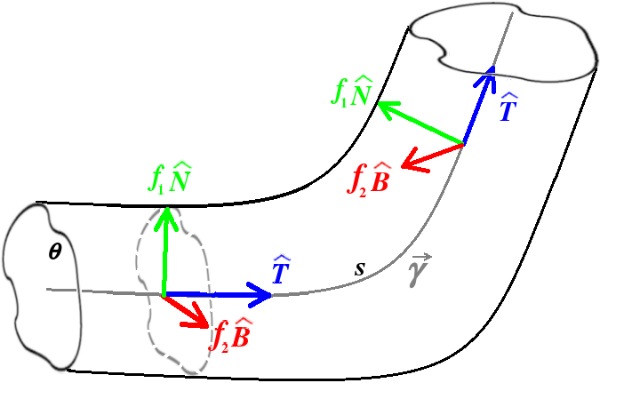
We can employ the Frenet-Serret frame to construct a cable model. Actually, we can propose a general cable as the region bounded by the following surface
| (5) |
here is an angular variable. Notice that employing the angular coordinate the functions and the vectors we are constructing the cable over the curve For example, a cable with a circular cross-section with radius can be parameterized with the functions
| (6) |
In the figure 1 we can see a representation of the surface (5).
Some geometric quantities as the area of a surface can be written in terms of the first fundamental form, which is constructed with the inner product on the tangent space of a surface docarmo . In the case of the surface (5) we have
| (9) |
where the first form coefficients are
| (10) | |||||
| (11) | |||||
| (12) | |||||
Using the first fundamental form, an area element of the cable surface (5) can be written as
| (13) |
where
| (14) | |||||
Notice, that the area element (13) depends on the curvature and the torsion of the curve
In particular, when the cable has a circular cross-section with radius namely when the cable is reparametrized with the functions (6), the area element of cable surface (5) is given by
| (15) | |||||
while the cable cross-section area is
| (16) |
We can see that the area element (15) does not depend on the torsion of the curve
Now, the Gaussian curvature characterizes the curvature of a surface docarmo . In particular, if the cable (5) has a circular cross-section with a constant radius the Gaussian curvature of the surface of this cable is given by
| (17) |
Notice that this quantity is singular when Because of the surfaces of the axons or dendrites reported are smooth surfaces, we can suppose that the Gaussian curvature of the surfaces of axons or dendrites does not have singularities. Notice that this hypothesis implies the inequality In addition, let us remember that the curvature at a point of the curve is defined as the inverse of the radius of the osculating circle at see spivak . Then, if at this point the cable radius is the radius of the osculating circle must be larger than Thus, at the point the curvature must be smaller than and the following inequality
| (18) |
is satisfied. In this paper we suppose that the inequality (18) is always satisfied.
Furthermore, notice that when constant the area element (15) is given by
| (19) |
and it depends on neither the torsion nor the curvature
In the next section we will propose a cable equation when a cable is described by (5).
III Cable equation
In order to propose a cable equation to a cable with the geometry given by the equation (5),
we break the curve into pieces. Each piece has a surface area and a cross sectional area
(
Now, we consider a current flow along the cable. Then, if is the membrane potential and is the resistance of the cable, from the Ohm’s law we have
| (20) |
In addition, due that the resistance to a cable with a cross-sectional area is jackson
| (21) |
where is the specific intracellular resistivity, from the Ohm’s law (20) we obtain
| (22) | |||||
Furthermore, if is the membrane capacitance, we get
| (23) |
which implies
| (24) |
Observe that the capacitance for the cable surface can be taken as
| (25) |
where is the specific membrane capacitance. Thus, the equation (24) can be written as
| (26) |
Moreover, the total ionic current that flows across the membrane is
| (27) |
where is the current per unit area into and out of the cable.
Hence, the change in cable current is given by
| (28) |
which implies
then
| (29) |
Because of the cable surface area is given by the equation (13), we obtain
Thus, at the limit we arrive to
| (30) | |||||
This equation is the cable equation when the cable geometry is given by (5) and it depends on geometric quantities as the curvature and torsion of the cable.
In the general case, depends on the voltage and the equation (30) is a non linear differential equation. However, in the passive cable model we can take
| (31) |
Therefore, the cable equation for the passive cable model with the geometry given by (5) is
| (32) | |||||
For an infinite cable, the voltage has to satisfy the Dirichlet boundary condition, while for a finite cable the voltage has to satisfy the Neumann boundary condition ermentrout .
In the next section we will study some exactly solvable cases of the equation (32).
IV Circular cross-section
A cable with a deformed circular cross-section where the radius depends on the angle , namely can be modeled with the surface (5) where
| (33) |
In this case the cross-section area is given by
| (34) |
in addition we obtain
| (35) |
For this general cable geometry, to find solutions of the cable equation (32) is a difficult task. However, for some cases this equation can be simplified. For instance, when the cable has a circular cross-section, namely when the function (35) does not depend on the torsion of the cable Hence, in this case the cable equation (32) becomes
| (36) |
Notice that if the sectional area is constant, that is constant, the equation (36) is given by
| (37) |
Remarkably, this last equation depends on neither the curvature nor the torsion of the cable. Furthermore, the equation (37) is equivalent to the cable equation for a straight cylindrical cable (1). Observe that the equation (37) depends on the arc length parameter (2) instead of the lab frame coordinate This shows that the natural variables for the voltage are given by geometric quantities of the cable.
For an infinite cable, the solution of the equation (37) is
| (38) |
where is a constant with voltage dimensions and is a constant with length dimensions. Notice that in this case the initial condition
| (39) |
is satisfied, where is the Dirac delta function. Moreover, using the lab frame coordinate and the equation (2), the voltage (38) can be written as
Thus, if a cable has a constant radius the voltage in cable depends on neither the curvature nor the torsion.
Furthermore, in this case voltage is not different from the voltage for the straight cylindrical cable with the same radius.
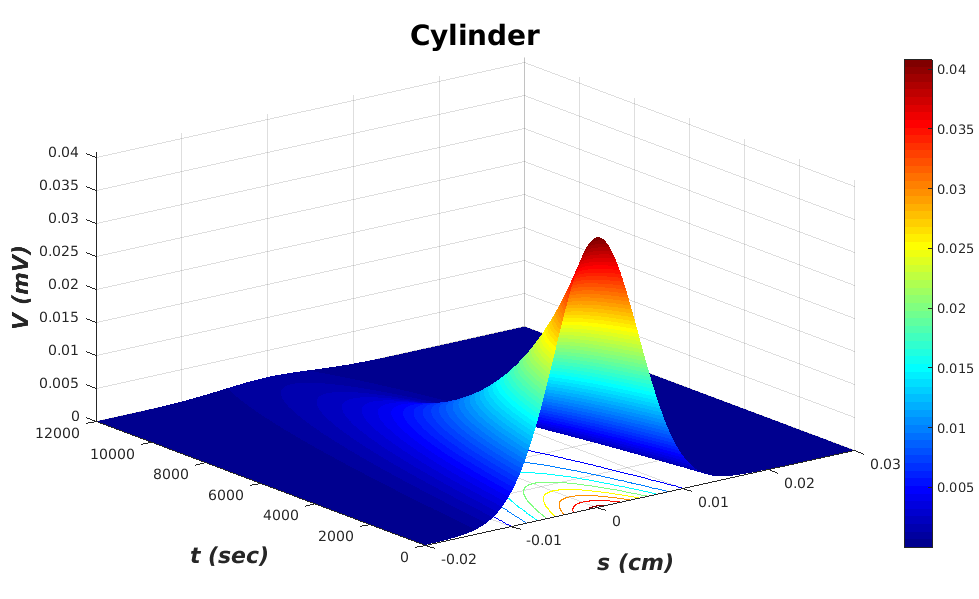
The figure 2 shows the cable equation solution for a cylindrical cable.
In the following sections we will study cables with a variable radius.
V An exact solution with a variable radius
Cables with a no constant radius are important for different reasons.
For example, discrete swellings along the axons appear in
neurodegenerative diseases such as Alzheimer, Parkinson, HIV-associated dementia and Multiple Sclerosis.
In particular, in Parkinson disease there are reported axons with a diameter of approximately with a swelling with diameter of approximately see Ga99 . In addition, in Multiple Sclerosis there are reported axons with a diameter of approximately
with a swelling with a diameter of approximately see Tr98 . In Alzheimer disease there are reported axons with a diameter of approximately with a swelling train, where the swelling diameter varies between and see Xi13 ; Jo13 ; Kr13 .
For HIV-associated dementia, there are reported axons with a diameter of approximately and swellings with a diameter of approximately
see Bu87 ; Bu871 ; Bu872 ; Bu873 ; Bu874 . Other sizes of the axonal swellings can be see in maia1 ; Sh98 .
When the radius is not a constant, the equation (36) is very complicated. However, some ideal cases can help
us to understand the general case. In this section, we study an ideal case
which does not represent a realistic axon or dendrite, but
it will help us to understand the generalized cable equation (32).
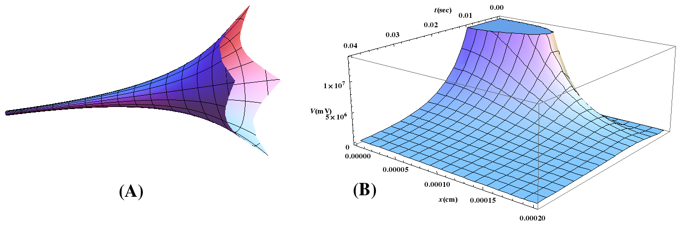
If the cable curvature vanishes and the radius is
| (40) |
the equation (36) becomes
which is solved by the voltage
| (41) |
Notice that when the radius (40) increases the voltage (41) decreases.
VI General properties
Studying the ideal cable (40) we learned that when the time increases the voltage (41) decreases. In addition, this voltage depends on , namely this voltage depends on where is the cable cross-section area. Then, inspired in the ideal case (41), in order to study the equation (32), we propose the following voltage
| (42) |
Thus, the equation (32) implies
| (43) |
where
Notice that the equation (43) can be interpreted as a diffusion equation with a source, in this equation the coefficient diffusion and the source term are generated by the cable geometry.
Now, we can see that if we take
| (44) |
where is a constant with (time)-1 dimensions, the equation (43) becomes
| (45) |
here
| (46) | |||||
If the equation (45) is the equilibrium description of the diffusion equation (43).
Moreover, in some cases the Fokker-Planck equation and the diffusion equation can be rewritten as a Schrödinger equation risken .
In this respect, notice that the equation (45) can be seen as a Schrödinger equation where is an effective potential, which is generated by the cable geometry.
In particular, when the radius of the cable is a constant the effective potential is the constant
| (47) |
When the radius is not a constant, the function is affected by the effective potential (46). For example, if the cable has a circular cross-section with radius the effective potential is
| (48) | |||||
From this last equation we can see that if the derivatives of the radius are small quantities, then the radius can be approximated by a constant and the effective potential can be approximated by a constant too.
In this case, the voltage in the cable is similar to the cylindrical cable. Moreover, observe that the condition (18) implies that is a small quantity. Then, when is a large quantity and the effective potential (48) depends on neither the curvature nor the torsion. Thus, in this last case, cables with similar swelling have similar voltage.
When the cable has a deformed circular cross-section with radius
we should introduce the equations (34) and (35) in the
effective potential (46). In this case we can see that the effective potential is affected by derivatives of the radius respect to the angle
Then, geometrical inhomogeneities on a cable might be affect the voltage.
In the next section we will provide numerical solution for cable with different geometries.
VII Numerical solutions
In this section the differential equation (32) is solved by using the second order finite differences method for both spatial coordinate and temporal evolution. The choice of mesh size was made with the usual procedure. First we begin with 1024 points along the s-axis and 50 points in the time. The meshes for s-direction and for the time were refined several times. We stop when no differences in solutions are obtained in two successive refinements. The number of spatial and temporal points used in the simulation is shown in Table 1.
| Refinement | ||
|---|---|---|
| First time | 1024 | 50 |
| Second time | 2048 | 80 |
| Third time | 4096 | 100 |
The system is solved using the Gauss-Seidel iterative method, with a tolerance of . Moreover, for the initial condition we used a gaussian shape
| (49) |
where and In addition we impose the Neumann boundary conditions ermentrout
VII.1 Cable with sinusoidal swelling
Now we study a cable with curvature and with the radius
| (50) |
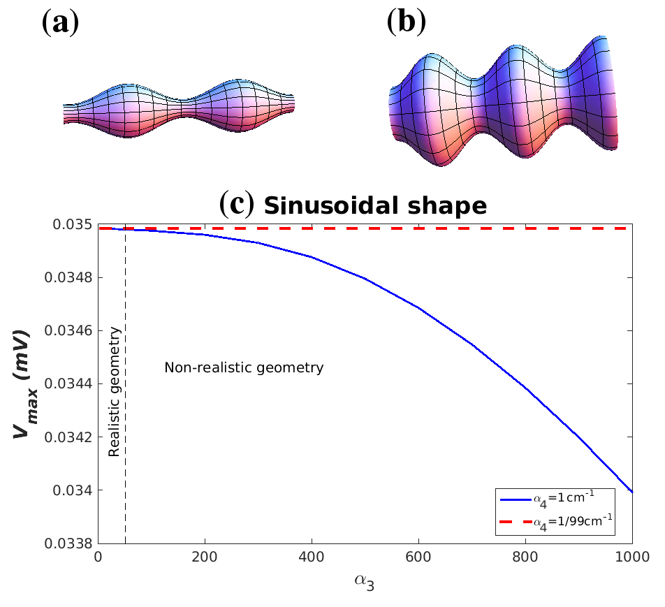
In the figure 4(a) we can see a cable with this geometry. Notice that in this case we should take Furthermore, in order to obtain a realistic cable geometry we should take Then, in this case the derivatives of radius of the cable are small quantities. In fact, for this cable the effective potential is given by
| (51) |
Notice that for realistic cable geometry the inequality is satisfied and the effective potential is a small quantity. Then, in this case the voltage in the cable is similar to voltage in the cylindrical cable.
A similar result is obtained when the radius of the cable is given by
| (52) |
In the figure 4(b) we can see a cable with this geometry.
Notice that in this case can be bigger than and for a realistic cable geometry
the condition cm-1 should be satisfied. It can be shown that in this case the effective potential (48) is a small quantity and then the voltage in the cable is also not different from the voltage for the cylindrical cable.
In the figure 4(c) we plot the maximum voltage as a function of for two different values of
We can see that the voltage to cable with a realistic geometry is not different from the voltage for a cylindrical cable.
VII.2 Cable with Gaussian swelling
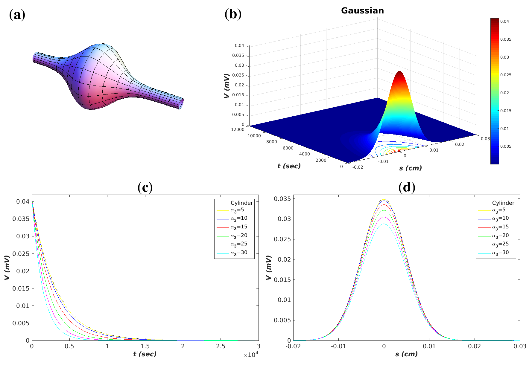
Now, we study a cable with the radius
| (53) |
In the figure 5(a) can see a cable with this geometry. The numerical solution to the voltage can be seen in the figure 5(b). In this figure we can see that the voltage decreases faster than the voltage to the cylindrical cable. Notice that for this geometry when the height of the swelling (53) increases the voltage of the cable decreases. In fact, for a big parameter the voltage can be blocked.
VII.3 Cable with Gaussian swellings
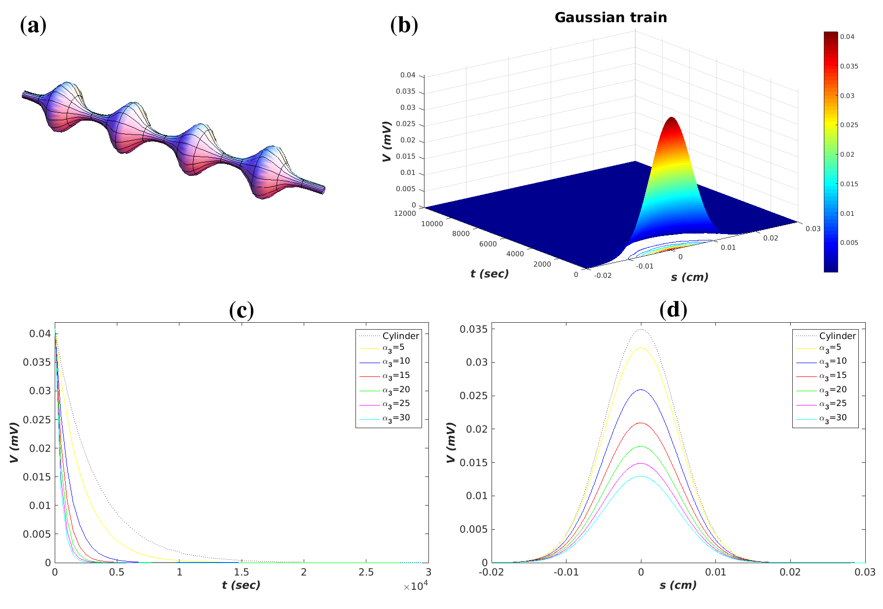
In this section we study the cable with the following radius
| (54) | |||||
A cable with this geometry can be seen in the figure 6(a) and the numerical solution to the voltage in this cable can be seen in the figure 6(b). In this case we can see that the voltage decreases faster than the voltage to the cylindrical cable. Moreover, notice that for this geometry when the height of the swelling (54) increases the voltage of the cable decreases. Observe that the voltage in this cable decreases more than the voltage in the cable with radius (53). Actually, if is a big parameter the voltage can be blocked.
VII.4 Amorphous swelling
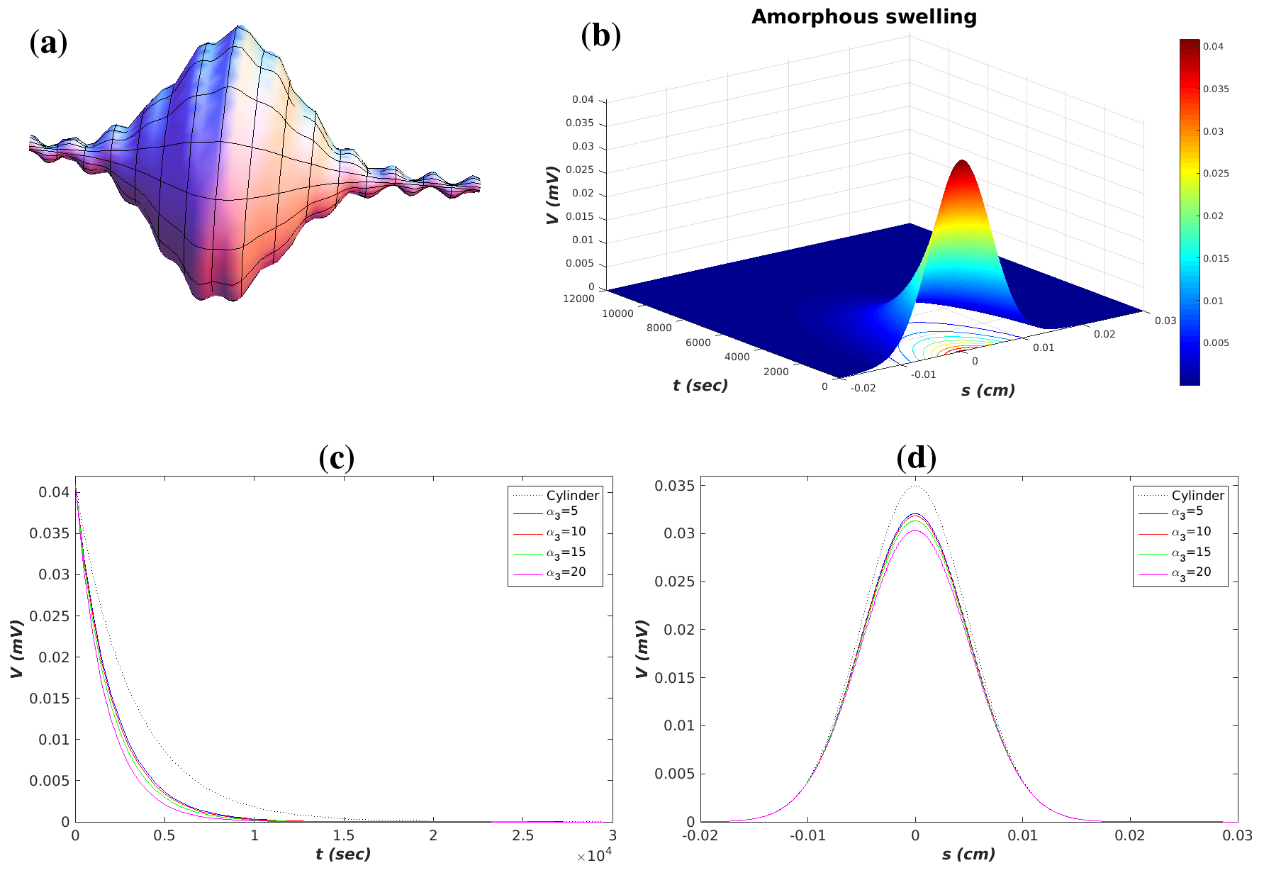
In the literature there are reported axons with amorphous swelling maia . For an amorphous cable we can propose the following radius
| (55) |
A cable with this geometry can be seen in the figure 7(a) and the numerical solution for the voltage in this cable can be seen in the figure
7(b), (c), (d). In this case we can see that the voltage decreases faster than the voltage to the cylindrical cable. In addition, observe that the voltage in this cable decreases more than the voltage in the cable with radius (53). Thus, geometric inhomogeneities in a cable can change its voltage in it.
Axons with swellings are hallmark features of some neurodegenerative diseases such as Alzheimer, Parkinson, HIV-associated dementia and Multiple Sclerosis maia ; maia1 ; yin .
The numerical results of this section indicate us when the cable geometry is important to the voltage propagation. These results show that when the derivatives of the cable radius are slowly changing functions, namely when and
the voltage is similar to voltage in a straight cylindrical cable. However, when these derivatives
change significantly the voltage cable is reduced and, in a extreme case, it can be blocked. Moreover, these numerical results show that geometric inhomogeneities in a cable can affect the voltage.
VIII Summary
In this paper, using the Frenet-Serret frame, we proposed a cable with general geometry and construct
a generalized cable equation to the voltage in it. This generalized equation depends on geometric quantities as curvature and torsion of the
cable. For the general case, this equation is very complicated to obtain exact solutions. However, when the cable has
a constant circular cross-section, we showed that the equation depends on neither the curvature nor the torsion of the cable. In fact, in this last case the new equation is equivalent to the cable equation for a straight cylindrical cable, where the voltage depends
on the arc length parameter. This shows that the natural variables for the voltage are given
by the cable geometric quantities.
Additionally, we found an exact solution
for an ideal cable with a particular non constant circular cross-section and zero curvature. In this last case, we show that when the radius increases the voltage decreases.
Inspired in this ideal case,
we rewrote the generalized cable equation as a diffusion equation with a source term.
In this diffusion equation the source term and the diffusion coefficient are generated by the cable geometry.
Furthermore, we provided numerical solutions to the new cable equation to different cable with swelling.
These solutions show that when the derivatives of the cable radius are slowly changing functions the voltage is similar to voltage in a straight cylindrical cable. However, when these derivatives
change significantly the voltage cable is reduced and, in a extreme case, it can be blocked. Moreover, these numerical results show that geometric inhomogeneities in a cable can change its voltage in it. The results of this paper might help us to understand the the behaviour of the voltage in focal axonal swellings which appears in some neurodegenerative diseases such as Alzheimer, Parkinson, HIV-associated dementia and Multiple Sclerosis maia .
In this work we did not study the active case, but we can argue that when the cable has a constant circular cross-section
the active case is not different from the usual active cylindrical cable. In a future work we will study the active cable case and some important cable geometries, for instance the spiny cable geometry.
Acknowledgements.
This work was supported in part by CONACyT-SEP 47510318 (J.M.R.). We are grateful to referees for providing valuable comments.References
- (1) W. Rall, Cable Theory for Dendritic Neurons, in Methods in Neuronal Modeling: From Synapses to Networks, eds. C. Koch and I. Segev (MIT Press, 1989) Chap. 2.
- (2) W. Rall, Theoretical significance of dendritic trees for neuronal input-output relations, in Neural Theory and Modeling, ed. R. F. Reiss, (Sanford University Press, Stanford, 1964) p. 73.
- (3) G. B. Ermentrout and D. H. Terman, Mathematical foundation of neuroscience, Springer, London, 2010 .
- (4) P. C. Bressloff, Waves in Neural Media: From Single Neurons to Neural Fields, Springer, London, 2014.
- (5) Q. Caudron, S. R. Donnelly, S. P. C. Brand and Y. Timofeeva, J. Math. Neurosci. 2 (1), 11 (2012).
- (6) P. D. Maia, M.A. Hemphill, B. Zehnder, C. Zhang, K. K. Parker, J. N. Kutz, Diagnostic tools for evaluating the impact of Focal Axonal Swellings arising in neurodegenerative diseases and/or traumatic brain injury, Journal of Neuroscience Methods 253, 233 (2015).
- (7) M. H. Magdesian, F. S. Sanchez, M. Lopez, P. Thostrup, N. Durisic, W. Belkaid, D. Liazoghli, P. Grütter and D.R. Colman, Atomic Force Microscopy Reveals Important Differences in Axonal Resistance to Injury, Biophysical Journal 103, 405 (2012).
- (8) T. C. Yin, J. R. Voorhees, R. M. Genova, K. C. Davis, A. M. Madison, J. K. Britt, C. J. Cintrón-Pérez, L. McDaniel, M. M. Harper, A. A. Pieper, Acute Axonal Degeneration Drives Development of Cognitive, Motor, and Visual Deficits after Blast-Mediated Traumatic Brain Injury in Mice, eNeuron 3 (5) e0220-16 (2016).
- (9) P. Vetter, A. Roth and M. Hausser, Propagation of action potentials in dendrites depends on dendritic morphology, Neurophysiol 85, 926 (2001).
- (10) A. D. Bird and H. Cuntz, Optimal current transfer in dendrites, PLoS Comput Biol. 12 (5): e1004897 (2016).
- (11) F. Santamaria, S. Wils, E. De Schutter and G. J. Augustine, Neuron 52, 4 (2006).
- (12) E. R. Kandel, J. H. Schwartz and T. N. Jessell, Principles of Neural Science, McGraw-Hill, New York, 2000.
- (13) J. C. Fiala and K. M. Harris, Dendrite Structure, in Dendrites, eds. G. Stuart, N. Spruston, M. H usser, (Oxford University Press, 1999) p.1.
- (14) R. R. Poznanski, Bull. Math. Biol. 54, 905 (1992).
- (15) H. Anwar, C. J. Roome, H. Nedelescu, W. Chen, B. Kuhn and E. De Schutter, Front. Cell. Neurosci. 8, 168 (2014).
- (16) K. A. Lindsay, J. R. Rosenberg and G. Tucker, From Maxwell’s equations to the cable equation and beyond, Progress in Biophysics and Molecular Biology 85, 71 (2004).
- (17) C. Bedárd and A. Destexhe, Generalized cable theory for neurons in complex and heterogeneous media, Phys. Rev. E 88, 022709 (2013).
- (18) C. Bedárd and A. Destexhe, Generalized cable formalism to calculate the magnetic field of single neurons and neuronal populations, Phys. Rev. E 90, 042723 (2014)
- (19) M. P. Do Carmo, Differential Geometry of Curves and Surfaces, Dover, NewYork (2016).
- (20) M. Spivak, A Comprehensive Introduction to Differential Geometry, vol. II, Publish or Perish (1975).
- (21) W. Greiner, Classical Electrodynamics, Springer-Verlag, NewYork (1991).
- (22) J. E. Galvin, K. Uryu, V. M.-Y. Lee and J. Q. Trojanowski, Axon pathology in Parkinson’ s disease and Lewy body dementia hippocampus contains -, -, and -synuclein, Proceedings of the National Academy of Sciences of the United States of America, Proceedings of the National Academy of Sciences 96 (23), 13450 (1999).
- (23) B. D. Trapp, J. Peterson, R. M. Ransohoff, R. Rudick, S. Mörk and L. Bö, Axonal Transection In The Lesions Of Multiple Sclerosis, The New England Journal of Medicine 338 (5), 278 (1998) .
- (24) V. E. Johnson, W. Stewart and D. H. Smith, Axonal Pathology in Traumatic Brain Injury, Experimental Neurology 246, 35 (2013).
- (25) D. Krstic and I. Knuesel, Deciphering the mechanism underlying late-onset Alzheimer disease, Nature Reviews Neuroscience 9, 25 (2013).
- (26) H. Xie, J. Guan, L. A. Borrelli, J. Xu, A. Serrano-Pozo and B. J. Bacskai, Mitochondrial Alterations near Amyloid Plaques in an Alzheimer’s Disease Mouse Model, The Journal of Neuroscience 33 (43), 17042 (2013).
- (27) H. Budka, G. Costanzi, S. Cristina, A. Leehi, C. Parravicini, R. Trabattoni, and L. Vago, Brain pathology induced by infection with the human immunodeficiency virus (HIV), Acta Neuropathologica 75 , 185 (1987).
- (28) F. Gray, F. Chrétien, A. V. Vallat-Decouvelaere and F. Scaravilli, The Changing Pattern of HIV Neuropathology in the HAART Era, Journal of Neuropathology and Experimental Neurology 62 (5), 429 (2003).
- (29) M. Kaul, G. A. Garden and S. A. Lipton, Pathways to neuronal injury and apoptosis in HIV-associated dementia, Nature 410, 988 (2001).
- (30) F. Raja, F. E. Sherriff, C. S. Morris, L. R. Bridges and M. M. Esiri, Cerebral white matter damage in HIV infection demonstrated using -amyloid precursor protein immunoreactivity, Acta Neuropathologica 93, 184 (1997).
- (31) R. Ellis, D. Langford and E. Masliah, HIV and antiretroviral therapy in therain: neuronal injury and repair, Nature Reviews Neuroscience 8, 33 (2007).
- (32) G. M. G. Shepherd and K. M. Harris, Three-Dimensional Structure and Composition of CA3CA1 Axons in Rat Hippocampal Slices: Implications for Presynaptic Connectivity and Compartmentalization, The Journal of Neuroscience 18 (20), 8300 (1980).
- (33) H. Risken, The Fokker-Planck Equation, Methods of Solution and Applications, Springer-Verlag, NewYork (1989).