Strong spin-orbit interaction of light on the surface of atomically thin crystals

Mengxia Liu    Liang Cai    Shizhen Chen    Yachao Liu    Hailu Luo hailuluo@hnu.edu.cn    Shuangchun Wen Laboratory for Spin Photonics, School of Physics and Electronics, Hunan University, Changsha 410082,China
Abstract

The photonic spin Hall effect (SHE) can be regarded as a direct optical analogy of the SHE in electronic systems where a refractive index gradient plays the role of electric potential. However, it has been demonstrated that the effective refractive index fails to adequately explain the light-matter interaction in atomically thin crystals. In this paper, we examine the spin-orbit interaction on the surface of the freestanding atomically thin crystals. We find that it is not necessary to involve the effective refractive index to describe the spin-orbit interaction and the photonic SHE in the atomically thin crystals. The strong spin-orbit interaction and giant photonic SHE have been predicted, which can be explained as the large polarization rotation of plane-wave components in order to satisfy the transversality of photon.

spin-orbit interaction, photonic spin Hall effect, atomic thin crystals
pacs:
42.25.-p, 42.79.-e, 41.20.Jb

I Introduction

Two-dimensional (2D) atomic crystals have extraordinary electronic and photonic properties which hold great promise in the application of photonics and optoelectronics Novoselov2004 ; Novoselov2005 ; Bonaccorso2010 . A fundamental understanding of the light-matter interaction in the 2D atomically thin crystals is therefore essential to optoelectronics applications. Reflection and refraction are most common optical phenomena, which are governed by the boundary condition Jackson1999 . In general, the interpretation of reflection and refraction on the surface of 2D atomically thin crystals is treated as a homogeneous medium with an effective refractive index and an effective thickness Blake2007 ; Bruna2009 ; Kravets2010 ; Peters2011 ; Zhou2012 ; Golla2013 . Recently, it has been demonstrated that the Fresnel model based on the certain thickness and effective refractive index fails to explain the overall experiments on light-matter interaction Merano2016I ; Merano2016II ; Merano2016III . However, the Fresnel model based on the zero-thickness interface can give a complete and convincing description of all the experimental observation. Here, the 2D atomic crystals can be regarded as zero-thickness interface (a real 2D system).

As a fundamental physical effect in light-matter interaction, spin-orbit coupling of light is attributed to the transverse nature of the photonic polarization. Photonic spin Hall effect (SHE) manifesting itself as spin- dependent splitting in light-matter interaction is considered as a result of spin-orbit interaction of light Onoda2004 ; Bliokh2006 ; Hosten2008 . The photonic SHE can be regarded as a direct optical analogy of the SHE in electronic systems Dyakonov1971 ; Hirsch1999 ; Murakami2003 ; Sinova2004 ; Wunderlich2005 where the spin electrons and electric potential are replaced by spin photons and a refractive index gradient, respectively. The analogy has been extensively demonstrated effective for the photonic SHE in 3D bulk crystals Bliokh2007 ; Bliokh2008 ; Aiello2008 ; Luo2009 ; Menard2010 ; Luo2011 ; Zhou2013 ; Korger2014 ; Ren2015 . However, the effective refractive index fails to adequately explain the light-matter interaction in 2D atomic crystals. It would be interesting how to describe the spin-orbit interaction on the surface of 2D atomic crystals.

In this paper, we examine the spin-orbit coupling of light on the surface of the freestanding atomically thin crystals. We develop a general model to describe the spin-orbit interaction of light on the surface of 2D atomic crystals. We find that it is not necessary to involve the effective refractive index to describe the spin-orbit interaction and photonic SHE on the surface of atomically thin crystals. Based on this model, the spin-dependent spatial and angular shifts in photonic SHE can be obtained. The strong spin-orbit interaction and the giant photonic SHE have been predicted, which can be explained as the large polarization rotation of plane-wave components in order to satisfy the transversality of photon.

II A general model for spin-orbit interaction of light

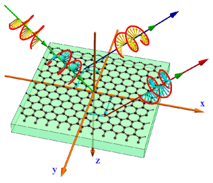
We first establish a general model to describe the spin-orbit interaction on the surface of 2D atomic crystals. Let us consider a Gaussian wavepacket with monochromatic frequency ω𝜔\omega impinging from air to the surface of the 2D atomic crystal as shown in Fig. 1. The z𝑧z axis of the laboratory Cartesian frame (x,y,z𝑥𝑦𝑧x,y,z) is normal to the surface of the 2D atomic crystal. A sheet of 2D atomic crystal is placed on the top of a dielectric substrate. In addition, the coordinate frames (xi,yi,zisubscript𝑥𝑖subscript𝑦𝑖subscript𝑧𝑖x_{i},y_{i},z_{i}) and (xr,yr,zrsubscript𝑥𝑟subscript𝑦𝑟subscript𝑧𝑟x_{r},y_{r},z_{r}) are used to denote central wave vector of incidence and reflection, respectively.

Refer to caption

Figure 1: Schematic illustrating the photonic SHE of wavepacket reflected on the surface of atomically thin crystal. On the surface of 2D atomic crystal, the photonic SHE occurs which manifests as the spin-dependent splitting. For the freestanding atomically thin crystal, we can choose the refractive index of substrate as n=ε/ε0=1𝑛𝜀subscript𝜀01n=\sqrt{\varepsilon/\varepsilon_{0}}=1.

In order to keep the discussion as general as possible, the conductivity and susceptibility tensors for the 2D atomic crystals can be written as

σT=(σppσpsσspσss),χT=(χppχpsχspχss).formulae-sequencesubscript𝜎𝑇subscript𝜎𝑝𝑝subscript𝜎𝑝𝑠missing-subexpressionsubscript𝜎𝑠𝑝subscript𝜎𝑠𝑠missing-subexpressionsubscript𝜒𝑇subscript𝜒𝑝𝑝subscript𝜒𝑝𝑠missing-subexpressionsubscript𝜒𝑠𝑝subscript𝜒𝑠𝑠missing-subexpression\displaystyle\sigma_{T}=\left(\begin{array}[]{lcr}\sigma_{pp}&\sigma_{ps}\\ \sigma_{sp}&\sigma_{ss}\end{array}\right),~{}~{}~{}\chi_{T}=\left(\begin{array}[]{lcr}\chi_{pp}&\chi_{ps}\\ \chi_{sp}&\chi_{ss}\end{array}\right). (5)

The conductivity and susceptibility tensors can be applied to describe different 2D atomic crystals, such as graphene Novoselov2004 , boron-nitride Geim2013 , and black phosphorus FXia2014 .

Based on the boundary conditions, the incident, reflected, and transmitted amplitudes satisfy the following equations:

Eis+Ers=Ets,subscriptsuperscript𝐸𝑠𝑖subscriptsuperscript𝐸𝑠𝑟subscriptsuperscript𝐸𝑠𝑡\displaystyle E^{s}_{i}+E^{s}_{r}=E^{s}_{t}, (6)
cosθi(EipErp)=cosθtEtp,subscript𝜃𝑖subscriptsuperscript𝐸𝑝𝑖subscriptsuperscript𝐸𝑝𝑟subscript𝜃𝑡subscriptsuperscript𝐸𝑝𝑡\displaystyle\cos\theta_{i}(E^{p}_{i}-E^{p}_{r})=\cos\theta_{t}E^{p}_{t}, (7)
cosθiZ0(EisErs)subscript𝜃𝑖subscript𝑍0subscriptsuperscript𝐸𝑠𝑖subscriptsuperscript𝐸𝑠𝑟\displaystyle\frac{\cos\theta_{i}}{Z_{0}}(E^{s}_{i}-E^{s}_{r}) =\displaystyle= (σss+ikχssZ0+cosθtZ)Etssubscript𝜎𝑠𝑠𝑖𝑘subscript𝜒𝑠𝑠subscript𝑍0subscript𝜃𝑡𝑍subscriptsuperscript𝐸𝑠𝑡\displaystyle\left(\sigma_{ss}+\frac{ik\chi_{ss}}{Z_{0}}+\frac{\cos\theta_{t}}{Z}\right)E^{s}_{t} (8)
+(ikχspZ0+σsp)cosθtEtp,𝑖𝑘subscript𝜒𝑠𝑝subscript𝑍0subscript𝜎𝑠𝑝subscript𝜃𝑡subscriptsuperscript𝐸𝑝𝑡\displaystyle+\left(\frac{ik\chi_{sp}}{Z_{0}}+\sigma_{sp}\right)\cos\theta_{t}E^{p}_{t},
1Z0(Eip+Erp)1subscript𝑍0subscriptsuperscript𝐸𝑝𝑖subscriptsuperscript𝐸𝑝𝑟\displaystyle\frac{1}{Z_{0}}(E^{p}_{i}+E^{p}_{r}) =\displaystyle= (σppcosθt+ikχppZ0cosθt+1Z)Etpsubscript𝜎𝑝𝑝subscript𝜃𝑡𝑖𝑘subscript𝜒𝑝𝑝subscript𝑍0subscript𝜃𝑡1𝑍subscriptsuperscript𝐸𝑝𝑡\displaystyle\left(\sigma_{pp}\cos\theta_{t}+\frac{ik\chi_{pp}}{Z_{0}}\cos\theta_{t}+\frac{1}{Z}\right)E^{p}_{t} (9)
+(ikχpsZ0+σps)Ets.𝑖𝑘subscript𝜒𝑝𝑠subscript𝑍0subscript𝜎𝑝𝑠subscriptsuperscript𝐸𝑠𝑡\displaystyle+\left(\frac{ik\chi_{ps}}{Z_{0}}+\sigma_{ps}\right)E^{s}_{t}.

Here, p𝑝p and s𝑠s represent the parallel and perpendicular polarization states, respectively. θisubscript𝜃𝑖\theta_{i} is the angle of incidence, θtsubscript𝜃𝑡\theta_{t} is the transmission angle. Z0subscript𝑍0{Z_{0}} is the impedance in air and Z𝑍{Z} is the impedance in media. The Fresnel’s coefficients are determined by the incident and reflected amplitudes: rpp=Erp/Eipsubscript𝑟𝑝𝑝subscriptsuperscript𝐸𝑝𝑟subscriptsuperscript𝐸𝑝𝑖r_{pp}=E^{p}_{r}/E^{p}_{i} , rss=Ers/Eissubscript𝑟𝑠𝑠subscriptsuperscript𝐸𝑠𝑟subscriptsuperscript𝐸𝑠𝑖r_{ss}=E^{s}_{r}/E^{s}_{i}, rps=Erp/Eissubscript𝑟𝑝𝑠subscriptsuperscript𝐸𝑝𝑟subscriptsuperscript𝐸𝑠𝑖r_{ps}=E^{p}_{r}/E^{s}_{i} and rsp=Ers/Eipsubscript𝑟𝑠𝑝subscriptsuperscript𝐸𝑠𝑟subscriptsuperscript𝐸𝑝𝑖r_{sp}=E^{s}_{r}/E^{p}_{i}. From Eqs. (6)-(9), the Fresnel’s coefficients are obtained as

rpp=α+TαL+βα+Tα+L+β,subscript𝑟𝑝𝑝subscriptsuperscript𝛼𝑇superscriptsubscript𝛼𝐿𝛽superscriptsubscript𝛼𝑇superscriptsubscript𝛼𝐿𝛽r_{pp}=\frac{\alpha^{T}_{+}\alpha_{-}^{L}+\beta}{\alpha_{+}^{T}\alpha_{+}^{L}+\beta}, (10)
rss=αTα+L+βα+Tα+L+β,subscript𝑟𝑠𝑠subscriptsuperscript𝛼𝑇superscriptsubscript𝛼𝐿𝛽subscriptsuperscript𝛼𝑇superscriptsubscript𝛼𝐿𝛽r_{ss}=-\frac{\alpha^{T}_{-}\alpha_{+}^{L}+\beta}{\alpha^{T}_{+}\alpha_{+}^{L}+\beta}, (11)
rps=rsp=Λα+Tα+L+β.subscript𝑟𝑝𝑠subscript𝑟𝑠𝑝Λsubscriptsuperscript𝛼𝑇superscriptsubscript𝛼𝐿𝛽r_{ps}=-r_{sp}=\frac{\Lambda}{\alpha^{T}_{+}\alpha_{+}^{L}+\beta}. (12)

Here, α±L=(kizε±ktzε0+iε0kizktzχpp+kizktzσpp/ω)/ε0subscriptsuperscript𝛼𝐿plus-or-minusplus-or-minussubscript𝑘𝑖𝑧𝜀subscript𝑘𝑡𝑧subscript𝜀0𝑖subscript𝜀0subscript𝑘𝑖𝑧subscript𝑘𝑡𝑧subscript𝜒𝑝𝑝subscript𝑘𝑖𝑧subscript𝑘𝑡𝑧subscript𝜎𝑝𝑝𝜔subscript𝜀0\alpha^{L}_{\pm}=(k_{iz}\varepsilon\pm k_{tz}\varepsilon_{0}+i\varepsilon_{0}k_{iz}k_{tz}\chi_{pp}+k_{iz}k_{tz}\sigma_{pp}/\omega)/\varepsilon_{0}, α±T=ktz±kiz+ik2χss+ωμ0σsssubscriptsuperscript𝛼𝑇plus-or-minusplus-or-minussubscript𝑘𝑡𝑧subscript𝑘𝑖𝑧𝑖superscript𝑘2subscript𝜒𝑠𝑠𝜔subscript𝜇0subscript𝜎𝑠𝑠\alpha^{T}_{\pm}=k_{tz}\pm k_{iz}+ik^{2}\chi_{ss}+\omega\mu_{0}\sigma_{ss}, β=[ikizktzχps+kizktzσps/(ωε0)](ik2χps+ωμ0σps)/μ0𝛽delimited-[]𝑖subscript𝑘𝑖𝑧subscript𝑘𝑡𝑧subscript𝜒𝑝𝑠subscript𝑘𝑖𝑧subscript𝑘𝑡𝑧subscript𝜎𝑝𝑠𝜔subscript𝜀0𝑖superscript𝑘2subscript𝜒𝑝𝑠𝜔subscript𝜇0subscript𝜎𝑝𝑠subscript𝜇0\beta=-[ik_{iz}k_{tz}\chi_{ps}+k_{iz}k_{tz}\sigma_{ps}/(\omega\varepsilon_{0})](ik^{2}\chi_{ps}+\omega\mu_{0}\sigma_{ps})/\mu_{0}, Λ=2kizktz(ikχps+Z0σps)Λ2subscript𝑘𝑖𝑧subscript𝑘𝑡𝑧𝑖𝑘subscript𝜒𝑝𝑠subscript𝑍0subscript𝜎𝑝𝑠\Lambda=2k_{iz}k_{tz}(ik\chi_{ps}+Z_{0}\sigma_{ps}), kiz=kicosθisubscript𝑘𝑖𝑧subscript𝑘𝑖subscript𝜃𝑖k_{iz}=k_{i}\cos\theta_{i}, and ktz=ktcosθtsubscript𝑘𝑡𝑧subscript𝑘𝑡subscript𝜃𝑡k_{tz}=k_{t}\cos\theta_{t}; ε0subscript𝜀0\varepsilon_{0} , μ0subscript𝜇0\mu_{0} are permittivity and permeability in vacuum; ε𝜀\varepsilon is the permittivity of substrate; σppsubscript𝜎𝑝𝑝\sigma_{pp}, σsssubscript𝜎𝑠𝑠\sigma_{ss} and σpssubscript𝜎𝑝𝑠\sigma_{ps} (σspsubscript𝜎𝑠𝑝\sigma_{sp} ) denote the longitudinal, transverse, and crossing-conductance conductivity, respectively.

For horizontal polarization state |Hket𝐻|{H}\rangle and vertical polarization state |Vket𝑉|{V}\rangle, the reflected polarization states related to the incident polarization states can be written as [|H(kr)|V(kr)]T=MR[|H(ki)|V(ki)]Tsuperscriptdelimited-[]ket𝐻subscript𝑘𝑟ket𝑉subscript𝑘𝑟𝑇subscript𝑀𝑅superscriptdelimited-[]ket𝐻subscript𝑘𝑖ket𝑉subscript𝑘𝑖𝑇[|{{H}}({k}_{r})\rangle~{}|{{V}}({k}_{r})\rangle]^{T}={M}_{R}[|{H}({k}_{i})\rangle~{}|{V}({k}_{i})\rangle]^{T}. Here, MRsubscript𝑀𝑅{M}_{R} can be expressed as

[rpp2krycotθrpsk0rps+krycotθ(rpp+rss)k0rspkrycotθ(rpp+rss)k0rss2krycotθrpsk0],delimited-[]subscript𝑟𝑝𝑝2subscript𝑘𝑟𝑦𝜃subscript𝑟𝑝𝑠subscript𝑘0subscript𝑟𝑝𝑠subscript𝑘𝑟𝑦𝜃subscript𝑟𝑝𝑝subscript𝑟𝑠𝑠subscript𝑘0subscript𝑟𝑠𝑝subscript𝑘𝑟𝑦𝜃subscript𝑟𝑝𝑝subscript𝑟𝑠𝑠subscript𝑘0subscript𝑟𝑠𝑠2subscript𝑘𝑟𝑦𝜃subscript𝑟𝑝𝑠subscript𝑘0\displaystyle\left[\begin{array}[]{cc}r_{pp}-\frac{2k_{ry}\cot\theta r_{ps}}{k_{0}}&r_{ps}+\frac{k_{ry}\cot\theta(r_{pp}+r_{ss})}{k_{0}}\\ r_{sp}-\frac{k_{ry}\cot\theta(r_{pp}+r_{ss})}{k_{0}}&r_{ss}-\frac{2k_{ry}\cot\theta r_{ps}}{k_{0}}\end{array}\right], (15)

where k0=ω/csubscript𝑘0𝜔𝑐k_{0}=\omega/c is the wavevector in vacuum. In above equation, the boundary condition krx=kixsubscript𝑘𝑟𝑥subscript𝑘𝑖𝑥k_{rx}=-k_{ix} and kry=kiysubscript𝑘𝑟𝑦subscript𝑘𝑖𝑦k_{ry}=k_{iy} have been introduced. The polarizations associated with the angular spectrum components experience different rotations in order to satisfy the boundary condition after reflection.

In the spin basis set, the polarization states of |Hket𝐻|{H}\rangle and |Vket𝑉|{V}\rangle can be decomposed into two orthogonal spin components |H=(|++|)ket𝐻ketket|{H}\rangle=(|{+}\rangle+|{-}\rangle), and |V=i(||+)/2ket𝑉𝑖ketket2|{V}\rangle=i(|\mathbf{-}\rangle-|{+}\rangle)/\sqrt{2}, where |+ket|{+}\rangle and |ket|{-}\rangle represent the left- and right-circular polarization components, respectively. We assume that the wavefunction in momentum space can be specified by the following expression

|Φ=w02πexp[w02(kix2+kiy2)4],ketΦsubscript𝑤02𝜋subscriptsuperscript𝑤20superscriptsubscript𝑘𝑖𝑥2superscriptsubscript𝑘𝑖𝑦24|\Phi\rangle=\frac{w_{0}}{\sqrt{2\pi}}\exp\left[-\frac{w^{2}_{0}(k_{ix}^{2}+k_{iy}^{2})}{4}\right], (16)

where w0subscript𝑤0w_{0} is the width of wave function. The total wave function is made up of the packet spatial extent and the polarization state. From Eqs. (15) and (16), the reflected wave function |ψrHketsubscriptsuperscript𝜓𝐻𝑟|{\psi}^{H}_{r}\rangle and |ψrVketsubscriptsuperscript𝜓𝑉𝑟|{\psi}^{V}_{r}\rangle in the momentum space can be obtained as

|ψrHketsubscriptsuperscript𝜓𝐻𝑟\displaystyle|{\psi}^{H}_{r}\rangle =\displaystyle= rpp±irps2(1ikrxδx±H±ikryδy±H)plus-or-minussubscript𝑟𝑝𝑝𝑖subscript𝑟𝑝𝑠2plus-or-minusminus-or-plus1𝑖subscript𝑘𝑟𝑥superscriptsubscript𝛿limit-from𝑥plus-or-minus𝐻𝑖subscript𝑘𝑟𝑦superscriptsubscript𝛿limit-from𝑦plus-or-minus𝐻\displaystyle\frac{r_{pp}{\pm}ir_{ps}}{\sqrt{2}}(1{\mp}ik_{rx}\delta_{x\pm}^{H}{\pm}ik_{ry}\delta_{y\pm}^{H}) (17)
×exp[w02(kix2+kiy2)4]|±,absentsubscriptsuperscript𝑤20superscriptsubscript𝑘𝑖𝑥2superscriptsubscript𝑘𝑖𝑦24ketplus-or-minus\displaystyle\times\exp\left[-\frac{w^{2}_{0}(k_{ix}^{2}+k_{iy}^{2})}{4}\right]|\pm\rangle,
|ψrVketsubscriptsuperscript𝜓𝑉𝑟\displaystyle|{\psi}^{V}_{r}\rangle =\displaystyle= rpsirss2(1±ikrxδx±V±ikryδy±V)minus-or-plussubscript𝑟𝑝𝑠𝑖subscript𝑟𝑠𝑠2plus-or-minus1𝑖subscript𝑘𝑟𝑥superscriptsubscript𝛿limit-from𝑥plus-or-minus𝑉𝑖subscript𝑘𝑟𝑦superscriptsubscript𝛿limit-from𝑦plus-or-minus𝑉\displaystyle\frac{r_{ps}{\mp}ir_{ss}}{\sqrt{2}}(1{\pm}ik_{rx}\delta_{x\pm}^{V}{\pm}ik_{ry}\delta_{y\pm}^{V})
×exp[w02(kix2+kiy2)4]|±,absentsubscriptsuperscript𝑤20superscriptsubscript𝑘𝑖𝑥2superscriptsubscript𝑘𝑖𝑦24ketplus-or-minus\displaystyle\times\exp\left[-\frac{w^{2}_{0}(k_{ix}^{2}+k_{iy}^{2})}{4}\right]|\pm\rangle,

Here, δx±H=(rps/θi)/(rpp±irps)superscriptsubscript𝛿limit-from𝑥plus-or-minus𝐻subscript𝑟𝑝𝑠subscript𝜃𝑖plus-or-minussubscript𝑟𝑝𝑝𝑖subscript𝑟𝑝𝑠\delta_{x\pm}^{H}=(\partial r_{ps}/\partial\theta_{i})/(r_{pp}\pm ir_{ps}), δy±H=(rpp+rss)cotθ+rps/θ]/(rpp±irps)2icotθrps/[k0(rpp±irps)]\delta_{y\pm}^{H}=(r_{pp}+r_{ss})\cot\theta+\partial r_{ps}/\partial\theta]/(r_{pp}\pm ir_{ps})-2i\cot\theta r_{ps}/[k_{0}(r_{pp}\pm ir_{ps})], δx±V=(rps/θ)/(rss±irps)superscriptsubscript𝛿limit-from𝑥plus-or-minus𝑉subscript𝑟𝑝𝑠𝜃plus-or-minussubscript𝑟𝑠𝑠𝑖subscript𝑟𝑝𝑠\delta_{x\pm}^{V}=(\partial r_{ps}/\partial\theta)/(r_{ss}\pm ir_{ps}), δy±V=(rpp+rss)cotθ+rps/θ]/[(rss±irps)2icotθrps/[k0(rss±irps)]\delta_{y\pm}^{V}=(r_{pp}+r_{ss})\cot\theta+\partial r_{ps}/\partial\theta]/[(r_{ss}\pm ir_{ps})-2i\cot\theta r_{ps}/[k_{0}(r_{ss}\pm ir_{ps})]. For weak spin-orbit interaction, δrxH,Vw0much-less-thansubscriptsuperscript𝛿𝐻𝑉𝑟𝑥subscript𝑤0\delta^{H,V}_{rx}\ll{w_{0}} and δryH,Vw0much-less-thansubscriptsuperscript𝛿𝐻𝑉𝑟𝑦subscript𝑤0\delta^{H,V}_{ry}\ll{w_{0}}, the reflected wavefunctions can be written as

|ψrHketsuperscriptsubscript𝜓𝑟𝐻\displaystyle|{\psi}_{r}^{H}\rangle \displaystyle\approx rpp±irsp2exp(ikrxδrx±H±ikryδry±H)plus-or-minussubscript𝑟𝑝𝑝𝑖subscript𝑟𝑠𝑝2plus-or-minusminus-or-plus𝑖subscript𝑘𝑟𝑥superscriptsubscript𝛿limit-from𝑟𝑥plus-or-minus𝐻𝑖subscript𝑘𝑟𝑦superscriptsubscript𝛿limit-from𝑟𝑦plus-or-minus𝐻\displaystyle\frac{r_{pp}\pm ir_{sp}}{\sqrt{2}}\exp(\mp ik_{rx}\delta_{rx\pm}^{H}\pm ik_{ry}\delta_{ry\pm}^{H}) (19)
×exp[w02(kix2+kiy2)4]|±,absentsubscriptsuperscript𝑤20superscriptsubscript𝑘𝑖𝑥2superscriptsubscript𝑘𝑖𝑦24ketplus-or-minus\displaystyle\times\exp\left[-\frac{w^{2}_{0}(k_{ix}^{2}+k_{iy}^{2})}{4}\right]|\pm\rangle,
|ψrVketsuperscriptsubscript𝜓𝑟𝑉\displaystyle|{\psi}_{r}^{V}\rangle \displaystyle\approx rpsirss2exp(±ikrxδrx±V±ikryδry±V)minus-or-plussubscript𝑟𝑝𝑠𝑖subscript𝑟𝑠𝑠2plus-or-minusplus-or-minus𝑖subscript𝑘𝑟𝑥superscriptsubscript𝛿limit-from𝑟𝑥plus-or-minus𝑉𝑖subscript𝑘𝑟𝑦superscriptsubscript𝛿limit-from𝑟𝑦plus-or-minus𝑉\displaystyle\frac{r_{ps}\mp ir_{ss}}{\sqrt{2}}\exp(\pm ik_{rx}\delta_{rx\pm}^{V}\pm ik_{ry}\delta_{ry\pm}^{V}) (20)
×exp[w02(kix2+kiy2)4]|±.absentsubscriptsuperscript𝑤20superscriptsubscript𝑘𝑖𝑥2superscriptsubscript𝑘𝑖𝑦24ketplus-or-minus\displaystyle\times\exp\left[-\frac{w^{2}_{0}(k_{ix}^{2}+k_{iy}^{2})}{4}\right]|\pm\rangle.

Here, we have introduced the approximations: 1+iσkrxδrx±H,Vexp(iσkrxδrx±H,V)1𝑖𝜎subscript𝑘𝑟𝑥subscriptsuperscript𝛿𝐻𝑉limit-from𝑟𝑥plus-or-minus𝑖𝜎subscript𝑘𝑟𝑥subscriptsuperscript𝛿𝐻𝑉limit-from𝑟𝑥plus-or-minus1+i\sigma k_{rx}\delta^{H,V}_{rx\pm}\approx\exp(i\sigma k_{rx}\delta^{H,V}_{rx\pm}) and 1+iσkryδryH,Vexp(iσkryδryH,V)1𝑖𝜎subscript𝑘𝑟𝑦subscriptsuperscript𝛿𝐻𝑉𝑟𝑦𝑖𝜎subscript𝑘𝑟𝑦subscriptsuperscript𝛿𝐻𝑉𝑟𝑦1+i\sigma k_{ry}\delta^{H,V}_{ry}\approx\exp(i\sigma k_{ry}\delta^{H,V}_{ry}), where σ𝜎\sigma being the Pauli operator. The origin of the spin-orbit interaction terms exp(iσkrxδrxH,V)𝑖𝜎subscript𝑘𝑟𝑥subscriptsuperscript𝛿𝐻𝑉𝑟𝑥\exp(i\sigma k_{rx}\delta^{H,V}_{rx}) and exp(iσkryδryH,V)𝑖𝜎subscript𝑘𝑟𝑦subscriptsuperscript𝛿𝐻𝑉𝑟𝑦\exp(i\sigma k_{ry}\delta^{H,V}_{ry}) lie in the transverse nature of the photon polarization: The polarizations associated with the plane-wave components experience different rotations in order to satisfy the transversality in reflection. In general, the phases φG=krxδrxH,Vsubscript𝜑𝐺subscript𝑘𝑟𝑥subscriptsuperscript𝛿𝐻𝑉𝑟𝑥\varphi_{G}=k_{rx}\delta^{H,V}_{rx} and φG=kryδryH,Vsubscript𝜑𝐺subscript𝑘𝑟𝑦subscriptsuperscript𝛿𝐻𝑉𝑟𝑦\varphi_{G}=k_{ry}\delta^{H,V}_{ry} can be regarded as the spin-redirection Berry phases Berry1984 ; Bliokh2015 . It should be noted that the above approximations do not hold for strong spin-orbit interaction δrxH,Vw0subscriptsuperscript𝛿𝐻𝑉𝑟𝑥subscript𝑤0\delta^{H,V}_{rx}\approx{w_{0}} or δryH,Vw0subscriptsuperscript𝛿𝐻𝑉𝑟𝑦subscript𝑤0\delta^{H,V}_{ry}\approx{w_{0}} .

III Strong spin-orbit interaction

We now develop the theoretical mode to describe the strong spin-orbit interaction of light on the surface of atomically thin crystals. Here, we restrict the isotropic case (such as graphene and boron-nitride), where the Fresnel reflection coefficients rps=rsp=0subscript𝑟𝑝𝑠subscript𝑟𝑠𝑝0r_{ps}=r_{sp}=0. By making use of Taylor series expansion based on the arbitrary angular spectrum component, rppsubscript𝑟𝑝𝑝r_{pp} and rsssubscript𝑟𝑠𝑠r_{ss} can be expanded as a polynomial of kixsubscript𝑘𝑖𝑥k_{ix}:

rppsubscript𝑟𝑝𝑝\displaystyle r_{pp} =\displaystyle= rpp(kix=0)+kix[rpp(kix)kix]kix=0,subscript𝑟𝑝𝑝subscript𝑘𝑖𝑥0subscript𝑘𝑖𝑥subscriptdelimited-[]subscript𝑟𝑝𝑝subscript𝑘𝑖𝑥subscript𝑘𝑖𝑥subscript𝑘𝑖𝑥0\displaystyle r_{pp}(k_{ix}=0)+k_{ix}\left[\frac{\partial r_{pp}(k_{ix})}{\partial k_{ix}}\right]_{k_{ix}=0}, (21)
rsssubscript𝑟𝑠𝑠\displaystyle r_{ss} =\displaystyle= rss(kix=0)+kix[rss(kix)kix]kix=0.subscript𝑟𝑠𝑠subscript𝑘𝑖𝑥0subscript𝑘𝑖𝑥subscriptdelimited-[]subscript𝑟𝑠𝑠subscript𝑘𝑖𝑥subscript𝑘𝑖𝑥subscript𝑘𝑖𝑥0\displaystyle r_{ss}(k_{ix}=0)+k_{ix}\left[\frac{\partial r_{ss}(k_{ix})}{\partial k_{ix}}\right]_{k_{ix}=0}. (22)

To accurately describe the strong spin-orbit interaction, the Fresnel reflection coefficients are confined to the first order in Taylor series expansion. We then obtain

|ψr±Hketsubscriptsuperscript𝜓𝐻limit-from𝑟plus-or-minus\displaystyle|{\psi}^{H}_{r\pm}\rangle =\displaystyle= [rppkrxk0rppθiikrycotθik0(rpp+rss)\displaystyle\bigg{[}r_{pp}-\frac{k_{rx}}{k_{0}}\frac{\partial r_{pp}}{\partial\theta_{i}}{\mp}i\frac{k_{ry}\cot\theta_{i}}{k_{0}}(r_{pp}+r_{ss}) (23)
ikrxkrycotθik02(rppθi+rssθi)]\displaystyle{\mp}i\frac{k_{rx}k_{ry}\cot\theta_{i}}{k_{0}^{2}}\left(\frac{\partial r_{pp}}{\partial\theta_{i}}+\frac{\partial r_{ss}}{\partial\theta_{i}}\right)\bigg{]}
×exp[w02(krx2+kry2)4]|±absentsubscriptsuperscript𝑤20superscriptsubscript𝑘𝑟𝑥2superscriptsubscript𝑘𝑟𝑦24ketplus-or-minus\displaystyle\times\exp\left[-\frac{w^{2}_{0}(k_{rx}^{2}+k_{ry}^{2})}{4}\right]|\pm\rangle
|ψr±Vketsubscriptsuperscript𝜓𝑉limit-from𝑟plus-or-minus\displaystyle|{\psi}^{V}_{r\pm}\rangle =\displaystyle= [rsskrxk0rssθiikrycotθik0(rpp+rss)\displaystyle\bigg{[}r_{ss}-\frac{k_{rx}}{k_{0}}\frac{\partial r_{ss}}{\partial\theta_{i}}{\mp}i\frac{k_{ry}\cot\theta_{i}}{k_{0}}(r_{pp}+r_{ss}) (24)
ikrxkrycotθik02(rppθi+rssθi)]\displaystyle{\mp}i\frac{k_{rx}k_{ry}\cot\theta_{i}}{k_{0}^{2}}\left(\frac{\partial r_{pp}}{\partial\theta_{i}}+\frac{\partial r_{ss}}{\partial\theta_{i}}\right)\bigg{]}
×exp[w02(kix2+kiy2)4]|±.absentsubscriptsuperscript𝑤20superscriptsubscript𝑘𝑖𝑥2superscriptsubscript𝑘𝑖𝑦24ketplus-or-minus\displaystyle\times\exp\left[-\frac{w^{2}_{0}(k_{ix}^{2}+k_{iy}^{2})}{4}\right]|\pm\rangle.

The large polarization in momentum space (k𝑘k) will induces a giant spin-dependent splitting in position space.

Refer to caption

Figure 2: Strong spin-orbit interaction of light on the surface of 2D atomic crystals. The spatial shift (a) and angular shift (b) on the surface of 2D atomic crystals as a function of incident angles θisubscript𝜃𝑖\theta_{i} and the refractive index of substrate n𝑛n. The 2D atomic crystal is chosen as single-layer graphene with σpp=σss=6.08×10⁵Ωsubscript𝜎𝑝𝑝subscript𝜎𝑠𝑠6.08superscript105Ω\sigma_{pp}=\sigma_{ss}=6.08\times 10^{-5}\Omega, σps=σsp=0subscript𝜎𝑝𝑠subscript𝜎𝑠𝑝0\sigma_{ps}=\sigma_{sp}=0, χpp=χss=1.0×10⁹msubscript𝜒𝑝𝑝subscript𝜒𝑠𝑠1.0superscript109m\chi_{pp}=\chi_{ss}=1.0\times 10^{-9}\mathrm{m}, and χps=χsp=0subscript𝜒𝑝𝑠subscript𝜒𝑠𝑝0\chi_{ps}=\chi_{sp}=0.

The transverse spatial and angular shifts of wave-packet at initial position (zr=0subscript𝑧𝑟0z_{r}=0) are given by

yr±H,V=ψr±H,V|kry|ψr±H,Vψr±H,V|ψr±H,V.delimited-⟨⟩superscriptsubscript𝑦limit-from𝑟plus-or-minus𝐻𝑉quantum-operator-productsuperscriptsubscript𝜓limit-from𝑟plus-or-minus𝐻𝑉subscriptsubscript𝑘𝑟𝑦superscriptsubscript𝜓limit-from𝑟plus-or-minus𝐻𝑉inner-productsuperscriptsubscript𝜓limit-from𝑟plus-or-minus𝐻𝑉superscriptsubscript𝜓limit-from𝑟plus-or-minus𝐻𝑉\langle{y_{r\pm}^{H,V}}\rangle=\frac{\langle\psi_{r\pm}^{H,V}|\partial_{k_{ry}}|\psi_{r\pm}^{H,V}\rangle}{\langle\psi_{r\pm}^{H,V}|\psi_{r\pm}^{H,V}\rangle}. (25)
Θry±H,V=1k0ψr±H,V|kry|ψr±H,Vψr±H,V|ψr±H,V.delimited-⟨⟩superscriptsubscriptΘlimit-from𝑟𝑦plus-or-minus𝐻𝑉1subscript𝑘0quantum-operator-productsuperscriptsubscript𝜓limit-from𝑟plus-or-minus𝐻𝑉subscript𝑘𝑟𝑦superscriptsubscript𝜓limit-from𝑟plus-or-minus𝐻𝑉inner-productsuperscriptsubscript𝜓limit-from𝑟plus-or-minus𝐻𝑉superscriptsubscript𝜓limit-from𝑟plus-or-minus𝐻𝑉\langle{\Theta_{ry\pm}^{H,V}}\rangle=\frac{1}{k_{0}}\frac{\langle\psi_{r\pm}^{H,V}|{k_{ry}}|\psi_{r\pm}^{H,V}\rangle}{\langle\psi_{r\pm}^{H,V}|\psi_{r\pm}^{H,V}\rangle}. (26)

Substituting Eqs. (23) and (24) into Eqs. (25) and (26), respectively, the transverse spatial and angular shifts for two spin components are achieved.

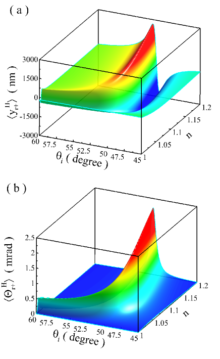
Figure 2 shows the transverse spatial and angular shifts for the |Hket𝐻|H\rangle polarization impinging on the surface of single-layer graphene. The transverse shifts are plotted as a function of incident angles and the refractive index of substrate. For one-layer graphene at wavelength 633nm633nm633\mathrm{nm}, the surface conductivity and the surface susceptibility values are chosen as 6.08×10⁵Ω6.08superscript105Ω6.08\times 10^{-5}\Omega and χpp=χss=1.0×10⁹msubscript𝜒𝑝𝑝subscript𝜒𝑠𝑠1.0superscript109m\chi_{pp}=\chi_{ss}=1.0\times 10^{-9}\mathrm{m}, respectively Merano2016I . The large spatial shifts occurs near a certain angle [Fig. 2(a)], which can be regarded as the Brewster angle on reflection at the interface of air-substrate Luo2011 . The large angular shifts present due to the surface conductivity and the surface susceptibility of the 2D atomic crystal [Fig. 2(b)]. It should be mentioned that there are no angular shifts present at the air-substrate interface. The incident angle associated the large spatial and angular shifts increase with the decrease of the reflective index. It should be interesting for the free standing 2D atomic crystals in vacuum where the refractive index of substrate is chosen as n=1𝑛1n=1.

Refer to caption

Figure 3: Giant spin-dependent shifts in photonic SHE when the wave packet is reflected from the surface of freestanding 2D atomically thin crystal. The spatial shifts (a) and the angular shifts (b) on the surface of atomically thin crystal with different layers m=1,2,3𝑚123m=1,2,3. The beam waist is chosen as w0=20μmsubscript𝑤020𝜇mw_{0}=20\mathrm{{\mu}m}. Other parameters are the same as in Fig. 2.

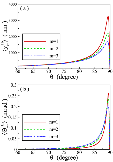
Assuming that an individual graphene sheet is a non-interacting monolayer, for few-layer graphene, the surface conductivity and the surface susceptibility values increase linearly with layer number m𝑚m. The parameters for multi-layer graphene are obtained as m×6.08×10⁵Ω𝑚6.08superscript105Ωm\times 6.08\times 10^{-5}\Omega and m×1.0×10⁹m𝑚1.0superscript109mm\times 1.0\times 10^{-9}\mathrm{m}. This assumption has been used to analyze the Goos-Hänchen effect on the surface of graphene, and the theoretic results coincide well with the experimental ones Chen2017 . Figure 3 shows the transverse spatial and angular shifts for the polarization impinging on the surface of free-standing graphene with different layers. The obtained spatial shift reaches 3000nm3000nm3000\mathrm{nm} near the grazing angle, which is several times larger than the wave length [Fig. 3(a)]. Correspondingly, the angular shifts reaches 0.25mrad0.25mrad0.25\mathrm{mrad} [Fig. 3(b)]. Note that the large spatial and angular shifts in Goos-Hänchen effect have been predicted theoretically Merano2016II . In addition, the quantized beam shifts Kamp2016 ; Cai2017 should also been enhanced in quantum Hall regime when the wavepacket reflection near the grazing angle.

We give a simple explanation of why the polarization rotation can be regarded as the origin of photonic SHE. In general, an arbitrary linear polarization state can be decomposed into two orthogonally circular polarization states with opposite phases:

(cosγsinγ)=exp(+iφG)|++exp(iφG)|,𝛾𝛾𝑖subscript𝜑𝐺ket𝑖subscript𝜑𝐺ket\displaystyle\left(\begin{array}[]{c}\cos\gamma\\ \sin\gamma\end{array}\right)=\exp(+i\varphi_{G})|\mathbf{+}\rangle+\exp(-i\varphi_{G})|\mathbf{-}\rangle, (29)

where γ𝛾\gamma is the polarization angle. The polarization rotation will induce a geometric phase gradient and ultimately lead to the spin-dependent shifts. When the polarization rotation occurs in momentum space, the spatial shift will be induced yr±=σφG/krydelimited-⟨⟩subscript𝑦limit-from𝑟plus-or-minus𝜎subscript𝜑𝐺subscript𝑘𝑟𝑦\langle{y_{r\pm}}\rangle=\sigma\partial\varphi_{G}/\partial{k_{ry}}. Similarly, when the polarization rotation occurs in position space, the angular shift will be induced Δkry±=σφG/yrΔsubscript𝑘limit-from𝑟𝑦plus-or-minus𝜎subscript𝜑𝐺subscript𝑦𝑟\Delta{k_{ry\pm}}=\sigma\partial\varphi_{G}/\partial{y_{r}} and Θry±=Δkry±/krdelimited-⟨⟩subscriptΘlimit-from𝑟𝑦plus-or-minusΔsubscript𝑘limit-from𝑟𝑦plus-or-minussubscript𝑘𝑟\langle{\Theta_{ry\pm}}\rangle=\Delta{k_{ry\pm}}/k_{r}.

Refer to caption

Figure 4: [(a) and (b)] Polarization rotation of the beam reflected on the surface of freestanding 2D atomic crystal without substrate. [(c) and (d)] Polarization rotation on the surface of the 3D bulk crystal n=1.515𝑛1.515n=1.515. The spin-orbit interaction can be explained as the polarization rotation in momentum space and position space. Left column: Polarization rotation in momentum space. Right column: Polarization rotation in position space. The incident angle is chosen as θi=85subscript𝜃𝑖superscript85\theta_{i}=85^{\circ} and the beam waist is chosen as w0=10μmsubscript𝑤010𝜇mw_{0}=10\mathrm{{\mu}m}. Other parameters are the same as in Fig. 2. To make the polarization rotation characteristics more noticeable, we amplify the rotation angles by 101010 times.

We now examine the polarization rotation characteristics of wave-packet after reflection. From Eqs. (15) and (16), the representation of the reflected wave function can be written as

|ψrHketsuperscriptsubscript𝜓𝑟𝐻\displaystyle|\psi_{r}^{H}\rangle =\displaystyle= exp[w02(krx2+kry2)4][(rppkrxk0rppθi)|H\displaystyle\exp\left[-\frac{w^{2}_{0}(k_{rx}^{2}+k_{ry}^{2})}{4}\right]\bigg{[}\left(r_{pp}-\frac{k_{rx}}{k_{0}}\frac{\partial r_{pp}}{\partial\theta_{i}}\right)|{H}\rangle (30)
krycotθik0(rpp+rss)|V+krxkrycotθik02subscript𝑘𝑟𝑦subscript𝜃𝑖subscript𝑘0subscript𝑟𝑝𝑝subscript𝑟𝑠𝑠ket𝑉subscript𝑘𝑟𝑥subscript𝑘𝑟𝑦subscript𝜃𝑖superscriptsubscript𝑘02\displaystyle-\frac{k_{ry}\cot\theta_{i}}{k_{0}}(r_{pp}+r_{ss})|{V}\rangle+\frac{k_{rx}k_{ry}\cot\theta_{i}}{k_{0}^{2}}
×(rppθi+rssθi)|V],\displaystyle\times\left(\frac{\partial r_{pp}}{\partial\theta_{i}}+\frac{\partial r_{ss}}{\partial\theta_{i}}\right)|{V}\rangle\bigg{]},
|ψrVketsuperscriptsubscript𝜓𝑟𝑉\displaystyle|\psi_{r}^{V}\rangle =\displaystyle= exp[w02(krx2+kry2)4][(rsskrxk0rssθi)|V\displaystyle\exp\left[-\frac{w^{2}_{0}(k_{rx}^{2}+k_{ry}^{2})}{4}\right]\bigg{[}\left(r_{ss}-\frac{k_{rx}}{k_{0}}\frac{\partial r_{ss}}{\partial\theta_{i}}\right)|{V}\rangle (31)
+krycotθik0(rpp+rss)|Hkrxkrycotθik02subscript𝑘𝑟𝑦subscript𝜃𝑖subscript𝑘0subscript𝑟𝑝𝑝subscript𝑟𝑠𝑠ket𝐻subscript𝑘𝑟𝑥subscript𝑘𝑟𝑦subscript𝜃𝑖superscriptsubscript𝑘02\displaystyle+\frac{k_{ry}\cot\theta_{i}}{k_{0}}(r_{pp}+r_{ss})|{H}\rangle-\frac{k_{rx}k_{ry}\cot\theta_{i}}{k_{0}^{2}}
×(rppθi+rssθi)|H],\displaystyle\times\left(\frac{\partial r_{pp}}{\partial\theta_{i}}+\frac{\partial r_{ss}}{\partial\theta_{i}}\right)|{H}\rangle\bigg{]},

The wave function in position space is the Fourier transform of the wave function in momentum space:

|ΦrH,V=𝑑krx𝑑kry|ψr±H,V|krx,kry.ketsuperscriptsubscriptΦ𝑟𝐻𝑉differential-dsubscript𝑘𝑟𝑥differential-dsubscript𝑘𝑟𝑦ketsuperscriptsubscript𝜓limit-from𝑟plus-or-minus𝐻𝑉ketsubscript𝑘𝑟𝑥subscript𝑘𝑟𝑦|\Phi_{r}^{H,V}\rangle=\int\int{dk_{rx}dk_{ry}}|\psi_{r\pm}^{H,V}\rangle|k_{rx},k_{ry}\rangle. (32)

In fact, after the angular spectrum of incident wave function is known, Eq. (32) together with Eqs. (30) and (31) provides the general representation of reflected wave function in position space:

|ΦrHketsuperscriptsubscriptΦ𝑟𝐻\displaystyle|\Phi_{r}^{H}\rangle =\displaystyle= exp[(xr2+yr2)w02][(rppixrzR)|H\displaystyle\exp\left[-\frac{(x_{r}^{2}+y_{r}^{2})}{w^{2}_{0}}\right]\bigg{[}\left(r_{pp}-\frac{ix_{r}}{z_{R}}\right)|{H}\rangle (33)
iyrzRcotθi(rpp+rss)|VxryrzR2cotθi𝑖subscript𝑦𝑟subscript𝑧𝑅subscript𝜃𝑖subscript𝑟𝑝𝑝subscript𝑟𝑠𝑠ket𝑉subscript𝑥𝑟subscript𝑦𝑟superscriptsubscript𝑧𝑅2subscript𝜃𝑖\displaystyle-\frac{iy_{r}}{z_{R}}\cot\theta_{i}(r_{pp}+r_{ss})|{V}\rangle-\frac{x_{r}y_{r}}{z_{R}^{2}}\cot\theta_{i}
×(rppθi+rssθi)]|V],\displaystyle\times\left(\frac{\partial r_{pp}}{\partial\theta_{i}}+\frac{\partial r_{ss}}{\partial\theta_{i}}\right)\bigg{]}|{V}\rangle\bigg{]},
|ΦrVketsuperscriptsubscriptΦ𝑟𝑉\displaystyle|\Phi_{r}^{V}\rangle =\displaystyle= exp[(xr2+yr2)w02][(rssixrzR)|V\displaystyle\exp\left[-\frac{(x_{r}^{2}+y_{r}^{2})}{w^{2}_{0}}\right]\bigg{[}\left(r_{ss}-\frac{ix_{r}}{z_{R}}\right)|{V}\rangle (34)
+iyrzRcotθi(rpp+rss)|H+xryrzR2cotθi𝑖subscript𝑦𝑟subscript𝑧𝑅subscript𝜃𝑖subscript𝑟𝑝𝑝subscript𝑟𝑠𝑠ket𝐻subscript𝑥𝑟subscript𝑦𝑟superscriptsubscript𝑧𝑅2subscript𝜃𝑖\displaystyle+\frac{iy_{r}}{z_{R}}\cot\theta_{i}(r_{pp}+r_{ss})|{H}\rangle+\frac{x_{r}y_{r}}{z_{R}^{2}}\cot\theta_{i}
×(rppθi+rssθi)|H].\displaystyle\times\left(\frac{\partial r_{pp}}{\partial\theta_{i}}+\frac{\partial r_{ss}}{\partial\theta_{i}}\right)|{H}\rangle\bigg{]}.

The above expressions are only confine to the isotropic case. For anisotropic 2D atomic crystals, more complex characteristics of polarization rotation would be involved.

We plot the polarization distributions of the reflected field in Fig. 4. In the reflection on the surface of the 2D atomic crystal, a large polarization rotation present in both position and momentum spaces [Fig. 4(a) and 4(b)]. Therefore, the large geometric phase gradient and giant spin-dependent splitting should also occur in momentum space and position space. As a comparison, the polarization rotation on the 3D bulk crystal are also plotted [Fig. 4(c) and 4(d)]. Interestingly, only a tiny polarization rotation appears in momentum space which ultimately induces a tiny spin-dependent splitting in position space. There are no polarization rotation appears in position space, and thereby no angular shift occurs in position space. Therefore, the spin-dependent splitting in position space is related to the polarization rotation in momentums space, while the splitting in momentum space is attributed to the polarization rotation in position space.

IV Conclusions

In conclusion, we have developed a general model to describe the spin-orbit interaction of light on the surface of the free standing atomically thin crystals. In this model, the 2D atomic crystals can be regarded as zero-thickness interface. We have found that it is not necessary to involve the effective refractive index to describe the spin-orbit interaction and the photonic SHE in the atomically thin crystals. The giant photonic SHE manifesting itself as large spin-dependent splitting in both position and momentum space have been theoretically predicted. This strong spin-orbit interaction can be explained as the large polarization rotation of plane-wave components in order to satisfy the transversality of photons. We believe that these results may provide insights into the fundamental properties of spin-orbit interaction of light in 2D atomic crystals.

Acknowledgements.
This research was supported by the National Natural Science Foundation of China (Grants Nos. 11274106 and 11474089).

References

  • (1) K. S. Novoselov, A. K. Geim, S. V. Morozov, D. Jiang, Y. Zhang, S. V. Dubonos, I. V. Grigorieva, and A. A. Firsov, Science 306, 666 (2004).
  • (2) K. Novoselov, D. Jiang, F. Schedin, T. Booth, V. Khotkevich, S. Morozov, and A. Geim, Proc. Natl. Acad. Sci. 102, 10451 (2005).
  • (3) F. Bonaccorso, Z. Sun, T. Hasan, and A. C. Ferrari, Nat. Photonics 4, 611 (2010).
  • (4) J. D. Jackson, Classical Electrodynamics (Wiley, New York, 1999).
  • (5) P. Blake, E. W. Hill, A. H. Castro Neto, K. S. Novoselov, D. Jiang, R. Yang, T. J. Booth, and A. K. Geim, Appl. Phys. Lett. 91, 063124 (2007).
  • (6) M. Bruna and S. Borini, Appl. Phys. Lett. 94, 031901 (2009).
  • (7) V. G. Kravets, A. N. Grigorenko, R. R. Nair, P. Blake, S. Anissimova, K. S. Novoselov, and A. K. Geim, Phys. Rev. B 81, 155413 (2010).
  • (8) K. Peters, A. Tittel, N. Gayer, A. Graf, V. Paulava, U. Wurstbauer, and W. Hansen, Appl. Phys. Lett. 99, 191912 (2011).
  • (9) X. Zhou, X. Li, H. Luo, and S. Wen, Appl. Phys. Lett. 101, 251602 (2012).
  • (10) D. Golla, K. Chattrakun, K. Watanabe, T. Taniguchi, B. J. LeRoy, and A. Sandhu, Appl. Phys. Lett. 102, 161906 (2013).
  • (11) M. Merano, Phys. Rev. A 93, 013832 (2016).
  • (12) M. Merano, Opt. Lett. 41, 2668 (2016).
  • (13) M. Merano, Opt. Lett. 41, 5780 (2016).
  • (14) M. Onoda, S. Murakami, and N. Nagaosa, Phys. Rev. Lett. 93, 083901 (2004).
  • (15) K. Y. Bliokh and Y. P. Bliokh, Phys. Rev. Lett. 96, 073903 (2006).
  • (16) O. Hosten and P. Kwiat, Science 319, 787 (2008).
  • (17) M. I. Dyakonov and V. I. Perel, Phys. Lett. A 35, 459 (1971).
  • (18) J. E. Hirsch, Phys. Rev. Lett. 83, 1834 (1999).
  • (19) S. Murakami, N. Nagaosa, and S. C. Zhang, Science 301, 1348 (2003).
  • (20) J. Sinova, D. Culcer, Q. Niu, N. A. Sinitsyn, T. Jungwirth, and A. H. MacDonald, Phys. Rev. Lett. 92, 126603 (2004).
  • (21) J. Wunderlich, B. Kaestner, J. Sinova, and T. Jungwirth, Phys. Rev. Lett. 94, 047204 (2005).
  • (22) K. Y. Bliokh and Y. P. Bliokh, Phys. Rev. E 75, 066609 (2007).
  • (23) K. Y. Bliokh, A. Niv, V. Kleiner, and E. Hasman, Nature Photon. 2, 748 (2008).
  • (24) A. Aiello and J. P. Woerdman, Opt. Lett. 33, 1437 (2008).
  • (25) H. Luo, S. Wen, W. Shu, Z. Tang, Y. Zou, and D. Fan, Phys. Rev. A 80, 043810 (2009).
  • (26) J.-M. Ménard, A. E. Mattacchione, H. M. van Driel, C. Hautmann, and M. Betz, Phys. Rev. B 82, 045303 (2010).
  • (27) H. Luo, X. Zhou, W. Shu, S. Wen, and D. Fan, Phys. Rev. A 84, 043806 (2011).
  • (28) X. Zhou, J. Zhang, X. Ling, S. Chen, H. Luo, and S. Wen, Phys. Rev. A 88, 053840 (2013).
  • (29) J. Korger, A. Aiello, V. Chille, P. Banzer, C. Wittmann, N. Lindlein, C. Marquardt, and G. Leuchs, Phys. Rev. Lett. 112, 113902 (2014).
  • (30) J. L. Ren, B. Wang, M. M. Pan, Y. F. Xiao, Q. H. Gong, and Y. Li, Phys. Rev. A 92, 013839 (2015).
  • (31) A. K. Geim and I. V. Grigorieva, Nature 499, 419 (2013).
  • (32) F. Xia, H. Wang, and Y. Jia, Nat. Commun. 5, 4458 (2014).
  • (33) M. V. Berry, Proc. R. Soc. London Ser. A 392, 45 (1984).
  • (34) K. Y. Bliokh, F. J. Rodríguez-Fortuño, F. Nori, and A. V. Zayats, Nat. Photonics 9, 796 (2015).
  • (35) S. Chen, C. Mi, L. Cai, M. Liu, H. Luo, and S. Wen, Appl. Phys. Lett. 110, 031105 (2017).
  • (36) W. J. M. Kort-Kamp, N. A. Sinitsyn, and D. A. R. Dalvit, Phys. Rev. B 93, 081410 (2016).
  • (37) L. Cai, M. Liu, S. Chen, Y. Liu, W. Shu, H. Luo, and S. Wen, Phys. Rev. A 95, 013809 (2017).