Octave-spanning dissipative Kerr soliton frequency combs in microresonators
Abstract
Octave-spanning, self-referenced frequency combs are applied in diverse fields ranging from precision metrology to astrophysical spectrometer calibration. The octave-spanning optical bandwidth is typically generated through nonlinear spectral broadening of femtosecond pulsed lasers. In the past decade, Kerr frequency comb generators have emerged as novel scheme offering chip-scale integration, high repetition rate and bandwidths that are only limited by group velocity dispersion. The recent observation of Kerr frequency combs operating in the dissipative Kerr soliton (DKS) regime, along with dispersive wave formation, has provided the means for fully coherent, broadband Kerr frequency comb generation with engineered spectral envelope. Here, by carefully optimizing the photonic Damascene fabrication process, and dispersion engineering of microresonators with free spectral range, we achieve bandwidths exceeding one octave at low powers () for pump lasers residing in the telecom C-band (), as well as in the O-band (). Precise dispersion engineering enables emission of two dispersive waves, increasing the power in the spectral ends of the comb, down to a wavelength as short as . Equally important, we find that for THz repetition rate comb states, conventional criteria applied to identify DKS comb states fail. Investigating the coherence of generated, octave-spanning Kerr comb states we unambiguously identify DKS states using a response measurement. This allows to demonstrate octave-spanning DKS comb states at both pump laser wavelengths of and including the broadest DKS state generated to date, spanning more than of optical bandwidth. Octave-spanning DKS frequency combs can form essential building blocks for metrology or spectroscopy, and their operation at enables applications in biological and medical imaging such as Kerr comb based optical coherence tomography or dual comb coherent anti-stokes Raman scattering.
I Introduction
Optical frequency combs with coherent optical bandwidths of one octave or more are required for many applications, such as precision spectroscopy (Udem et al., 2002), optical frequency synthesis (Holzwart et al., 2000) or astrophysical spectrometer calibration (Steinmetz et al., 2008). Conventionally these spectra are synthesized by nonlinear spectral broadening of a pulsed laser (Udem et al., 2002). However, ensuring coherent spectral broadening, a smooth spectral envelope, and sufficient power in the spectral ends for a given pulse source can be challenging, in particular for high repetition rate pulse sources. Kerr frequency combs (Del’Haye et al., 2007) have emerged as alternative scheme that enables compact form factor, high repetition rates and broadband optical frequency combs, that are even amenable to wafer-scale integration with additional electrical or optical functionality. The spectral bandwidth of Kerr frequency combs, being independent of a specific material gain and primarily determined by the resonator’s group velocity dispersion (GVD), has reached octave span shortly after the principle’s first demonstration (Del’Haye et al., 2011; Okawachi et al., 2011), although in the high noise operation regime (Herr et al., 2012). Only recently, the observation of dissipative Kerr soliton (DKS) formation in microresonators has enabled the controlled excitation of fully coherent Kerr frequency combs (Herr et al., 2014a).
When operated in the single soliton state, DKS frequency combs feature high coherence across their bandwidth and a smooth spectral envelope that can be numerically predicted with high accuracy using the Lugiato-Lefever equation or in frequency domain via coupled mode approaches (Coen et al., 2013; Okawachi et al., 2014; Herr et al., 2014a). Furthermore, higher order GVD causes soliton Cherenkov radiation, an oscillatory tail in the temporal soliton pulse profile, corresponding to a dispersive wave (DW) in the spectral domain, which extends the spectral comb bandwidth into the normal GVD regime (Akhmediev and Karlsson, 1995). Soliton Cherenkov radiation in microresonators is a fully coherent process and has e.g. allowed self-referencing and stabilization without additional spectral broadening via the --method (Brasch et al., 2017). These properties have made DKS states the preferred operational low noise states (Herr et al., 2012; Xue et al., 2015; Saha et al., 2013) of Kerr frequency comb generation with a growing number of applications having been demonstrated, including e.g. terabit coherent communications (Marin-Palomo et al., 2016), dual comb spectroscopy (Dutt et al., 2016; Suh et al., 2016) and low noise microwave generation (Liang et al., 2015). So far DKS formation has been observed in a variety of resonator platforms (Brasch et al., 2016; Herr et al., 2014a; Joshi et al., 2016; Liang et al., 2015; Yi et al., 2015; Wang et al., 2016) among which planar silicon nitride () waveguide resonators have gained significant attention. Allowing CMOS-compatible, wafer-scale fabrication and exhibiting low linear and nonlinear optical losses in the telecom wavelength region, microresonators bear realistic potential for applications (Moss et al., 2013). The accurate control of waveguide dimensions during microfabrication is prerequisite to precise GVD engineering and thus tailoring of the Kerr frequency comb bandwidth (Okawachi et al., 2014). Dual dispersive wave emission extending the spectral bandwidth to both sides is attractive for low power octave-spanning DKS generation but particularly challenging to realize as it requires control of higher order GVD. Most microresonators used for DKS generation to date, did not have specifically engineered GVD, resulting in limited spectral bandwidth, far below one octave.
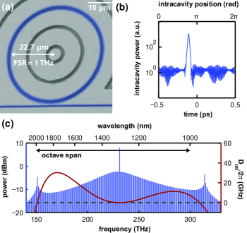
Here we present microresonators with a free spectral range (FSR) of which allow for DKS frequency comb generation with bandwidths exceeding one octave. The wide FSR reduces the total power requirements to cover one octave bandwidth and benefits the nonlinear conversion efficiency in the DKS state (Bao et al., 2014). Such microresonators are thus also of interest for wavelength regions where no high power pump sources exist. We use the recently developed photonic Damascene process (Pfeiffer et al., 2016a) for wafer-scale fabrication of such high-Q microresonator devices with high yield. Figure 1(a) shows a scanning electron microscope (SEM) picture of the microresonator device including a straight bus waveguide. For small microresonator radii () the coupling section forms a relatively large fraction of the total circumference and can cause parasitic loss. Thus, void-free fabrication of narrow coupling gaps, as provided by the photonic Damascene process, is important. Moreover, the bus waveguide cross section needs to be engineered for high ideality coupling (Pfeiffer et al., 2016b). The fundamental mode families of the microresonator devices used in this work have a typical internal linewidth of and thus a loaded finesse of at critical coupling.
While a high microresonator finesse is beneficial to lower the power threshold of Kerr comb generation, the microresonator GVD determines mostly the power requirements to reach a certain spectral bandwidth. Microresonator GVD is conveniently expressed in its integrated form around a central pump frequency :
is the resonance frequency deviation of the -th mode relative to the central pump mode from the equidistant grid defined by the repetition rate . DKS formation requires anomalous GVD () as the associated resonance frequency deviation is compensated by the nonlinear phase shift induced by the soliton. In the case of dominant quadratic GVD, the bandwidth of the resulting characteristic soliton spectral envelope, and thus the temporal pulse width, is a function of the cavity detuning and (Herr et al., 2014a). Low positive values of result in larger optical bandwidths for a given pump power and detuning. Beyond this, dispersive wave formation offers an effective way to coherently enlarge the bandwidth into the normal GVD with locally enhanced comb tooth power in the spectral ends (Brasch et al., 2016; Milián and Skryabin, 2014). Dispersive waves are emitted in resonances which are phase matched by the soliton induced nonlinear phase shift and the spectral positions of DWs are thus approximately given by the linear phase matching criterion . For dominant, negative fourth-order dispersion two DW positions can be engineered, causing dual dispersive wave emission.
We design the microresonator waveguide cross section based on finite element (FEM) simulations of the resonator’s mode family dispersion. Dispersive wave formation is engineered to occur around wavelengths of and spanning an octave bandwidth around the pump line at or . Full 3D finite difference time domain simulations are employed to engineer the bus waveguide cross section for high ideality coupling to the mode family (Pfeiffer et al., 2016b). Next, we simulate the octave-spanning DKS generation using a Lugiato-Lefever model (Coen et al., 2013; Lugiato and Lefever, 1987) for a critically coupled microresonator with linewidth driven by a pump laser of power. Figure 1(b), (c) show the intracavity field and the spectral envelope of the simulated single DKS state. As can be seen the two dispersive waves are present in the temporal intracavity field as trailing and following wave patterns which fill the complete cavity. Furthermore, close examination reveals that the position of the higher frequency dispersive wave is slightly offset from the linear phase-matching point, indicating the approximative nature of the criterion .
In the following, we first discuss the challenges of precise waveguide dimension control using the photonic Damascene process. Leveraging optimized fabrication procedures, we achieve control over the dispersive wave positions resulting in octave-spanning comb generation based on and pump lasers. The coherence of the generated Kerr frequency combs is studied and a response measurement is used to unambiguously identify DKS formation. Finally, we study octave-spanning single DKS formation for and pump wavelengths featuring the broadest Kerr soliton frequency comb generated to date, exceeding in bandwidth.
II Precision dispersion engineering using the photonic Damascene process
Dispersion engineering for octave-spanning Kerr frequency comb generation requires stringent waveguide width and height control on the order of , that is challenging to meet. As detailed below via simulations (shown in Figure 3), especially the position of the dispersive wave features is very sensitive to variations of the waveguide dimensions. Although DKS frequency comb generators have been fabricated using conventional subtractive processing, several challenges arise for the fabrication of high confinement waveguides for nonlinear applications. In particular, these are cracking of the highly stressed thin film and void formation at the microresonator coupling gap (Pfeiffer et al., 2016a). The recently reported photonic Damascene process, employed in the present work, solves these problems by depositing the thin film on a prestructured substrate and subsequent removal of the excess material using chemical mechanical planarization (CMP). A dense filler pattern surrounding the waveguide structures effectively lowers the thin film’s tensile stress and enables crack free fabrication even for micron thick waveguides. Moreover, the filler pattern helps to control and unify the material removal rate across the wafer during CMP.
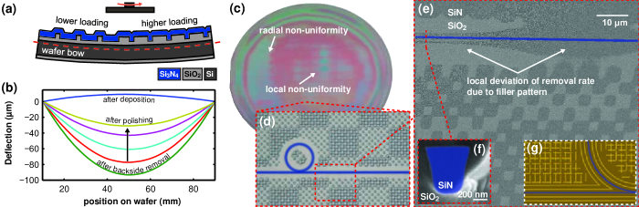
Although the level of control on the waveguide width is similar for Damascene and subtractive processing schemes (both relying on the precision of lithography and etching processes) the waveguide height control is substantially eased in the subtractive fabrication scheme: a typical thin film deposition non-uniformity of 3% across a 4” wafer results in a maximal height deviation for thick waveguides. For the Damascene process the variation of the final waveguide thickness depends on the uniformity of the dry etch process used to structure the waveguide trenches and most importantly on the uniformity of the CMP process. While optical interferometry can give precise local information on the removal rate during CMP, especially the wafer bow and the local loading lead to height variations (see Figure 2(a)). This reduces the yield of devices with dimensions within the tolerance range for octave-spanning Kerr comb generation, and causes uncontrolled spectral positions of the dispersive waves.
Figure 2(b) shows the evolution of the bow during planarization of a thick 4” wafer measured using a thin film stress measurement tool. After deposition, the continuous film on the wafer backside causes a positive deflection as its tensile stress is higher than the stress on the wafer front side which is reduced by the prestructured surface. The removal of the backside prior to the CMP inverts the bow to more than . The subsequent planarization step removes the excess on the front side and continuously relaxes the wafer bow. This bow variation leads to non-uniformity with radial symmetry visible as the colored interference ring pattern in Figure 2(c). Furthermore, local non-uniformity in the central wafer region can also be observed, which originates from different removal rates due to loading variations. Loading refers here to the amount of excess that is in direct contact with the polishing pad and depends on the local structure density. Such local variations can also occur on much smaller scales. This is exemplified in Figure 2(e) for an area around a bus waveguide (indicated in blue) after CMP. Depending on the loading of the neighboring filler pattern, more or less (darker shaded area) is remaining above the silicon dioxide () preform (lighter shaded area). Such loading dependent non-uniformity leads to local variations of the waveguide height, and therefore needs to be minimized. Finally, during landing when most excess is removed and mostly the preform is in contact with the polishing pad, the material removal rate can drastically change. Thus, the polishing endpoint is hard to predict and the overall mean waveguide height differs from the target value.

Here we apply an optimized CMP process that uses higher pressure to equalize the wafer bow and a thicker wafer substrate () that reduces the amount of initial wafer bow to . The removal rates for and are chosen to be similar, limiting the uncertainty during landing. In order to reduce local loading effects, a novel filler pattern (see Figure 2(g)) is used which homogenizes the loading while providing sufficient stress release for crack-free fabrication. The dispersion control achieved using this optimized CMP process is summarized in Figure 3. Based on FEM simulations of microresonator GVD shown in Figure 3(a), the target waveguide height of was chosen to enable octave-spanning DKS frequency comb generation in the resonator’s mode family for a pump laser. The simulation predicts dispersive wave formation around and for a wide, fully cladded waveguide with 82° sidewall angle. As shown in Figure 3(a), a waveguide height deviation of only causes a shift of the low frequency dispersive wave position by (i.e. ca. in wavelength). A change in the waveguide width does not strongly influence the position of the low frequency dispersive wave but changes the position of the high frequency dispersive wave.
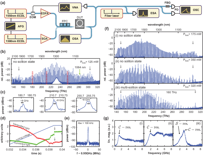
The dispersion of different samples is evaluated based on the spectral envelopes of the generated frequency combs. The low values of microresonator GVD (i.e. ) and the bandwidth limitations of our precision diode laser spectroscopy setup (Liu et al., 2016), did not allow to measure higher order dispersion terms. Figure 4(a) shows the setup used for DKS frequency comb generation. A external cavity diode laser (ECDL) is amplified using a tapered semiconductor amplifier (SOA) to a maximum power of . Laser light is coupled into the photonic chip using lensed fibers and inverse tapered waveguides with about loss per facet. During the laser tuning into the mode family resonance, the transmission through the device as well as the generated comb light are recorded using photodiodes (). Up to three optical spectrum analyzers (OSA) are used to capture the generated broadband comb spectra. Figure 3(b) shows octave spanning unstable modulation instability (uMI) comb states excited in three different microresonator chips. The sample position on the 4” wafer is provided as inset. As can be seen, the position variation of the low frequency dispersive wave for the three samples is around to the designed target value of . In comparison with the simulations in Figure 3(a) this indicates a variation of less than in waveguide height around the target value of . Moreover, the width variation allows the position of the high frequency dispersive wave to be tuned. A waveguide width reduction of in the design moves the position of the high frequency dispersive wave by in good agreement with simulations. These measurements reveal actual lithographic control over the dispersive wave position, rather than post fabrication selection. The photonic Damascene process with optimized planarization step thus offers sufficient precision in the control over waveguide dimensions to allow for wafer-scale fabrication of microresonators with engineered dispersion properties over a full octave of bandwidth.
III Coherence and soliton identification
For applications of the octave-spanning Kerr comb state coherence is a key requirement. Common methods to classify the coherence of Kerr comb states are the measurements of the low frequency amplitude noise of the generated comb light, the repetition rate beat-note, as well as heterodyne beat-notes with reference lasers (Herr et al., 2012). Among the different low noise comb states (Saha et al., 2013; Xue et al., 2015; Herr et al., 2012), the DKS state is particularly attractive as it provides high coherence across its entire bandwidth. Soliton Kerr comb states have in particular been identified via the characteristic transmission steps in the generated comb light, via the red-detuned nature of the pump laser, as well as the characteristic soliton spectral envelope. Although the spectra contain no direct information on coherence, for microresonators with dominant (positive) quadratic dispersion the single soliton state exhibits a characteristic spectral envelope. For broadband Kerr combs the spectral envelope can exhibit dispersive waves, due to higher order microresonator dispersion. Although dispersive wave features are also present in the uMI state spectra, in the DKS state their width reduces with a simultaneous increase in the individual comb tooth power and a shift of the dispersive wave maximum (Brasch et al., 2016). Other spectral signatures of the DKS regime include the soliton Raman self-frequency shift, that leads to a redshift of the soliton’s envelope with respect to the pump (Karpov et al., 2016). The Raman self-frequency shift is absent in the uMI comb state, but can be masked in the DKS state by the soliton recoil due to dispersive wave formation. For octave spanning soliton Kerr combs with THz mode spacing and dispersive wave emission due to microresonator GVD and avoided modal crossings (Yang et al., 2016), DKS state identification purely based on the spectral envelope is unreliable.
In contrast, a recently introduced response measurement technique (Guo et al., 2016) allows to unambiguously identify DKS comb states, and is applied here for the first time to octave spanning soliton states. Figure 4(a) shows the setup used to investigate the coherence of comb states generated with a and ECDL. The ECDL is amplified using an erbium-doped fiber amplifier (EDFA) and in order to perform the response measurement, a phase modulator with bandwidth is added before the amplifier. A vector network analyzer (VNA), probing the Kerr comb state’s response, drives the EOM and receives the signal via a photodiode with bandwidth. We note that this measurement was only possible using the pump laser due to the lack of an appropriate phase modulator for the pump path. A heterodyne beat note of the comb with a fiber laser at is recorded using an electrical spectrum analyzer (ESA). All presented Kerr frequency comb states are excited using a simple laser tuning method, applying a linear voltage ramp provided by an arbitrary function generator (AFG) to controllably tune into a comb state (Herr et al., 2014a; Guo et al., 2016).
DKS formation is accompanied by characteristic step features that occur simultaneously in the generated comb and transmitted light trace (Herr et al., 2014a). However, in the experiments reported here in Figure 4(b)-(d), we found that abrupt changes in the transmitted power do not necessarily originate from soliton formation. Instead, abrupt changes between different non-solitonic comb states, as well as resonance splitting due to waveguide surface roughness or near-by resonances of other mode families can cause similar features. Figure 4(b) shows the optical spectrum of a comb state generated by tuning the pump laser with in the bus waveguide into the step feature visible in Figure 4(d). The spectrum spans an octave and is highly structured, featuring individual sharp lines at the dispersive wave positions. Moreover, the beat-note of an individual comb tooth with a fiber laser at (see Figure 4(e)) shows low noise characteristics i.e. signal-to-noise ratio in a resolution bandwidth (RBW). Based on these measurements, the generated comb state would agree with properties associated with a multi-soliton state. However, close examination of the generated spectral lines, shown in Figure 4(c), reveals that certain comb lines have a splitting of , incompatible with a DKS comb state and associated with merging of individual subcombs (Herr et al., 2012). Importantly, commonly employed (Herr et al., 2012; Li et al., 2016) low frequency amplitude noise measurements, and even local heterodyne beat-note measurements, are insufficient discriminators, unless they are performed over sufficiently wide bandwidth to detect the subcomb spacing (here ). Indeed, for the measurements above, no noise is observed, which would lead to an erroneous soliton state identification.
A more reliable method is using the response of the comb state to a phase modulation of the pump laser. It was shown that the phase modulation response function of DKS states consists of two characteristic resonances originating from the circulating soliton pulses (-resonance) and the cavity response (-resonance) (Guo et al., 2016; Lucas et al., 2016). Furthermore, the measurement allows to infer the effective pump laser detuning within the DKS state, an important quantity determining the soliton properties. Figure 4(f) shows three comb states recorded from three microresonators on the same photonic chip having the same waveguide dimensions but varying bus-resonator distances. Again, the microresonator dispersion was designed for dispersive wave emission around and , here upon pumping with a laser. We excite different comb states and analyze their corresponding response functions shown in Figure 4(g). State (i) is a uMI state and the response function exhibits a single peak and a non-zero background noise at high frequencies. State (ii) has a much more structured spectral envelope and a seemingly sharp dispersive wave feature compared to state (i). However, the response measurement reveals a fundamentally different response than expected for a DKS state. Also, state (iii) has a strongly structured spectral envelope with similarities to the envelope of state (ii) but its response function shows two overlapping resonances. The lower frequency -resonance originates from the circulating soliton pulses and has a reduced amplitude compared to the cavity -resonance at higher frequency, whose frequency indicates the detuning. Moreover, the separation of both peaks diminishes upon laser blue detuning and increases for red detuning, respectively. We thus identify state (iii) as a multi-soliton state. The multi-soliton state leads to an increased conversion efficiency compared to the single soliton case, resulting in negligible residual pump power in the present case. Moreover, we observe a notable shift of the high frequency dispersive wave peak position (indicated by gray arrows).
IV Octave spanning spectra via single soliton generation
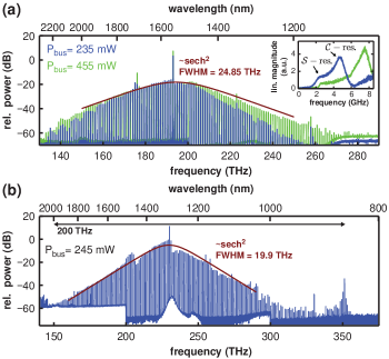
Once excited, a multi-soliton state can often be converted into a single soliton state by soliton switching upon “backward tuning” of the pump laser (Guo et al., 2016). Figure 5 shows two examples of octave-spanning single soliton generation obtained via this technique using or pump lasers. We note that not all multi-soliton states excited were observed to switch to a lower soliton number upon backward tuning, but some changed into non-solitonic states. Moreover, it is observed that both single soliton combs are excited in direct vicinity of an avoided modal crossing causing strong local deviations from the characteristic shaped spectral envelope (Herr et al., 2014b).
The soliton spectrum shown in Figure 5(a) features no dispersive waves indicating a dominant quadratic factor of the anomalous GVD. The response measurement shown in the inset shows a double resonance signature and reveals a cavity detuning of . The pump power is increased to in the bus waveguide while maintaining the single DKS state, which allows for a larger soliton existence range and octave bandwidth at a cavity detuning of . This cavity detuning is significantly higher than previously published values for microresonators indicating a strong nonlinear phase shift due to the high peak intensity of the soliton pulse (Guo et al., 2016). The spectral envelope is fitted using a shape and a bandwidth of is extracted, corresponding to a pulse. In Figure 5(b) we present the broadest single DKS comb state published to date, to the best of our knowledge. The DKS comb spans a total bandwidth of using a pump laser at providing only power in the bus waveguide. The fitted bandwidth of is similar to the value of the single DKS state shown in Figure 5(a) even though the required pump power is significantly lower. This demonstrates the strong influence of dispersion on the power requirements for broadband comb generation and underlines the necessity for precise dispersion control.
V Conclusion
In conclusion, we have demonstrated DKS generation in microresonators with FSR and spectral bandwidths exceeding one octave, both at and pump wavelength. The photonic Damascene process with optimized planarization step allows for high yield, wafer-scale fabrication of microresonators with precisely controlled dispersive wave positions. Our work moreover revealed that for comb states generated in microresonators with FSR, conventional criteria of coherence can fail. We carefully investigated the coherence of generated comb states and unambiguously identified octave-spanning multi-DKS states based on their unique phase modulation response signature. Finally, we demonstrated single soliton generation with record bandwidth of generated with only of pump power.
Our findings demonstrate the technological readiness of the photonic Damascene process and integrated frequency comb generators for a wide range of applications. The ability to generate ultra-short pulses also with a pump laser, as demonstrated here, opens up applications in biological and medical imaging as this wavelength represents a compromise between low tissue scattering and absorption due to water. Moreover, such DKS frequency combs with designed spectral envelopes may in the future enable chip integration and miniaturization of self-referenced frequency combs (Bowers et al., 2016) and dual comb CARS (Ideguchi et al., 2013).
Acknowledgements
microresonator samples were fabricated in the Center of MicroNanoTechnology (CMi) at EPFL.
This publication was supported by Contract HR0011-15-C-0055 from the Defense Advanced Research Projects Agency (DARPA), Defense Sciences Office (DSO), funding from Air Force Office of Scientific Research, Air Force Material Command, USAF under Award No. FA9550-15-1-0099, the European Union’s Horizon 2020 research and innovation programme under MIRCOMB: Marie Sklodowska-Curie IF grant agreement No. 709249 and the Swiss National Science Foundation under grant agreement No.161573 and 163864. M.K. acknowledges the support from the Marie Curie Initial Training Network FACT.
This research was carried out concurrently with the work from K. S. at NIST in the framework of the project DODOS that is available online under (Li et al., 2016) and also reports octave spanning Kerr soliton combs with dual dispersive waves.
References
- Udem et al. (2002) T. Udem, R. Holzwarth, and T. W. Hänsch, Nature 416, 233 (2002).
- Holzwart et al. (2000) R. Holzwart, T. Udem, T. W. Hänsch, J. Knight, W. J. Wadsworth, and P. Russel, Physical Review Letters 85, 2264 (2000).
- Steinmetz et al. (2008) T. Steinmetz, T. Wilken, C. Araujo-Hauck, R. Holzwarth, T. W. Hänsch, L. Pasquini, A. Manescau, S. D’Odorico, M. T. Murphy, T. Kentischer, W. Schmidt, and T. Udem, Science 321, 1335 (2008), arXiv:0809.1663 .
- Del’Haye et al. (2007) P. Del’Haye, A. Schliesser, O. Arcizet, T. Wilken, R. Holzwarth, and T. J. Kippenberg, Nature 450, 1214 (2007).
- Del’Haye et al. (2011) P. Del’Haye, T. Herr, E. Gavartin, M. L. Gorodetsky, R. Holzwarth, and T. J. Kippenberg, Physical Review Letters 107, 063901 (2011).
- Okawachi et al. (2011) Y. Okawachi, K. Saha, J. S. Levy, Y. H. Wen, M. Lipson, and A. L. Gaeta, Optics Letters 36, 3398 (2011).
- Herr et al. (2012) T. Herr, K. Hartinger, J. Riemensberger, C. Y. Wang, E. Gavartin, R. Holzwarth, M. L. Gorodetsky, and T. J. Kippenberg, Nature Photonics 6, 480 (2012).
- Herr et al. (2014a) T. Herr, V. Brasch, J. D. Jost, C. Y. Wang, N. M. Kondratiev, M. L. Gorodetsky, and T. J. Kippenberg, Nature Photonics 8, 145 (2014a), arXiv:1211.0733 .
- Coen et al. (2013) S. Coen, H. G. Randle, T. Sylvestre, and M. Erkintalo, Optics Letters 38, 37 (2013), arXiv:1211.1697 .
- Okawachi et al. (2014) Y. Okawachi, M. R. E. Lamont, K. Luke, D. O. Carvalho, M. Yu, M. Lipson, and A. L. Gaeta, Optics Letters 39, 3535 (2014), arXiv:arXiv:1307.1037 .
- Akhmediev and Karlsson (1995) N. Akhmediev and M. Karlsson, Physical Review A 51, 2602 (1995).
- Brasch et al. (2017) V. Brasch, E. Lucas, J. D. Jost, M. Geiselmann, and T. J. Kippenberg, Light: Science & Applications 6, 1 (2017), arXiv:1605.02801 .
- Xue et al. (2015) X. Xue, Y. Xuan, Y. Liu, P.-H. Wang, S. Chen, J. Wang, D. E. Leaird, M. Qi, and A. M. Weiner, Nature Photonics 9, 594 (2015).
- Saha et al. (2013) K. Saha, Y. Okawachi, B. Shim, J. S. Levy, R. Salem, A. R. Johnson, M. A. Foster, M. R. E. Lamont, M. Lipson, and A. L. Gaeta, Optics Express 21, 1335 (2013).
- Marin-Palomo et al. (2016) P. Marin-Palomo, J. N. Kemal, M. Karpov, A. Kordts, J. Pfeifle, M. H. P. Pfeiffer, P. Trocha, S. Wolf, V. Brasch, R. Rosenberger, K. Vijayan, W. Freude, T. J. Kippenberg, and C. Koos, arXiv 1610.01484, 13 (2016), arXiv:1610.01484 .
- Dutt et al. (2016) A. Dutt, C. Joshi, X. Ji, J. Cardenas, Y. Okawachi, K. Luke, A. L. Gaeta, and M. Lipson, arXiv 1611.07673, 1 (2016), arXiv:1611.07673 .
- Suh et al. (2016) M.-G. Suh, Q. Yang, K. Yang, X. Yi, and K. J. Vahala, Science 354, 600 (2016).
- Liang et al. (2015) W. Liang, D. Eliyahu, V. S. Ilchenko, A. A. Savchenkov, A. B. Matsko, D. Seidel, and L. Maleki, Nature Communications 6, 7957 (2015).
- Brasch et al. (2016) V. Brasch, M. Geiselmann, T. Herr, G. Lihachev, M. H. P. Pfeiffer, M. L. Gorodetsky, and T. J. Kippenberg, Science 351, 357 (2016).
- Joshi et al. (2016) C. Joshi, J. K. Jang, K. Luke, X. Ji, S. A. Miller, A. Klenner, Y. Okawachi, M. Lipson, and A. L. Gaeta, Optics Letters 41, 1 (2016), arXiv:1603.08017 .
- Yi et al. (2015) X. Yi, Q.-F. Yang, K. Y. Yang, M.-G. Suh, and K. J. Vahala, Optica 2, 1078 (2015).
- Wang et al. (2016) P.-H. Wang, J. A. Jaramillo-Villegas, Y. Xuan, X. Xue, C. Bao, D. E. Leaird, M. Qi, and A. M. Weiner, Optics Express 24, 10890 (2016), arXiv:arXiv:1601.05036 .
- Moss et al. (2013) D. J. Moss, R. Morandotti, A. L. Gaeta, and M. Lipson, Nature Photonics 7, 597 (2013).
- Bao et al. (2014) C. Bao, L. Zhang, A. B. Matsko, Y. Yan, Z. Zhao, G. Xie, A. M. Agarwal, L. C. Kimerling, J. Michel, L. Maleki, and A. E. Willner, Optics Letters 39, 6126 (2014).
- Pfeiffer et al. (2016a) M. H. P. Pfeiffer, A. Kordts, V. Brasch, M. Zervas, M. Geiselmann, J. D. Jost, and T. J. Kippenberg, Optica 3, 20 (2016a), arXiv:1511.05716 .
- Pfeiffer et al. (2016b) M. H. P. Pfeiffer, J. Liu, M. Geiselmann, and T. J. Kippenberg, arXiv 1608.06607, 1 (2016b), arXiv:1608.06607 .
- Milián and Skryabin (2014) C. Milián and D. V. Skryabin, Optics Express 22, 3732 (2014).
- Lugiato and Lefever (1987) L. A. Lugiato and R. Lefever, Physical Review Letters 58, 2209 (1987).
- Liu et al. (2016) J. Liu, V. Brasch, M. H. P. Pfeiffer, A. Kordts, A. Kamel, H. Guo, M. Geiselmann, and T. J. Kippenberg, Optics Letters 41, 3134 (2016).
- Karpov et al. (2016) M. Karpov, H. Guo, A. Kordts, V. Brasch, M. H. P. Pfeiffer, M. Zervas, M. Geiselmann, and T. J. Kippenberg, Physical Review Letters 116, 103902 (2016).
- Yang et al. (2016) Q.-F. Yang, X. Yi, K. Y. Yang, and K. J. Vahala, Optica 3, 1132 (2016), arXiv:1606.00954 .
- Guo et al. (2016) H. Guo, M. Karpov, E. Lucas, A. Kordts, M. H. P. Pfeiffer, V. Brasch, G. Lihachev, V. E. Lobanov, M. L. Gorodetsky, and T. J. Kippenberg, Nature Physics 13 (2016), 10.1038/nphys3893.
- Li et al. (2016) Q. Li, T. C. Briles, D. A. Westly, T. E. Drake, J. R. Stone, R. B. Ilic, S. A. Diddams, S. B. Papp, and K. Srinivasan, arXiv 1611.09229, 16 (2016), arXiv:1611.09229 .
- Lucas et al. (2016) E. Lucas, J. D. Jost, and T. J. Kippenberg, arXiv 1609.02723, 16 (2016), arXiv:1609.02723 .
- Herr et al. (2014b) T. Herr, V. Brasch, J. D. Jost, I. Mirgorodskiy, G. Lihachev, M. L. Gorodetsky, and T. J. Kippenberg, Physical Review Letters 113, 1 (2014b), arXiv:1311.1716 .
- Bowers et al. (2016) J. E. Bowers, A. Beling, D. J. Blumenthal, A. Bluestone, S. M. Bowers, T. C. Briles, L. Chang, S. A. Diddams, G. Fish, H. Guo, T. J. Kippenberg, T. Komljenovic, E. Norberg, S. B. Papp, M. H. P. Pfeiffer, K. Srinivasan, L. Theogarajan, K. J. Vahala, and N. Volet, 2016 IEEE International Frequency Control Symposium, IFCS 2016 - Proceedings (2016), 10.1109/FCS.2016.7546782.
- Ideguchi et al. (2013) T. Ideguchi, S. Holzner, B. Bernhardt, G. Guelachvili, N. Picqué, and T. W. Hänsch, Nature 502, 355 (2013), arXiv:1302.2414 .