Fabrication of a centimeter-long cavity on a nanofiber for cavity QED
Abstract
We report the fabrication of a 1.2 cm long cavity directly on a nanofiber using femtosecond laser ablation. The cavity modes with finesse value in the range 200-400 can still maintain the transmission between 40-60%, which can enable “strong-coupling” regime of cavity QED for a single atom trapped 200 nm away from the fiber surface. For such cavity modes, we estimate the one-pass intra-cavity transmission to be 99.53%. Other cavity modes, which can enable high cooperativity in the range 3-10, show transmission over 60-85% and are suitable for fiber-based single photon sources and quantum nonlinear optics in the “Purcell”regime.
Efficient quantum state transfer between single photons and single atom is a key challenge towards realization of quantum networks kimble1 . Interaction of a single atom with strongly confined photons in an optical cavity leading to cavity QED effects, is a promising approach to realize a quantum interface kimble1 ; berman ; rempe review . A crucial requirement to achieve strong interaction between single photon and single atom, is that the single atom cooperativity parameter , where is the single photon Rabi frequency, is the cavity decay rate (linewidth) and is the atomic spontaneous emission rate in vacuum. Even with , there are two regimes with different dynamics, a) “Purcell” regime, when and b) “strong-coupling” regime, when . The “strong-coupling” regime has been investigated using free-space Fabry-Perot (FP) cavities, where the coherent quantum phenomena like single-atom lasing and vacuum Rabi oscillations have been demonstrated kimble2 ; kimble3 ; rempe review . However, it requires extremely high finesse of 0.3 to 0.5 million, which is technically challenging. Although high quality mirrors with transmission and scattering loss less than 2 ppm has been reported, but the overall cavity transmission may drop to 10-20% rempe review ; rempe cavity transmission . Following the development of free-space FP cavities, various designs of nanophotonic cavities have also been developed and investigated. In particular, the designs have focused on the “Purcell” regime, for applications like single photon generation, single photon switching and quantum nonlinear optics, where high transmission is essential rempe review ; lukin .
In the vision of a quantum network, efficient integration of the quantum interface to the existing fiber network is also an essential requirement. In this context, optical nanofiber based cavities offer a flexible alternative platform famsan2 . The nanofiber is the subwavelength diameter waist of a tapered single mode optical fiber. Using adiabatic tapering condition adiabatic , efficient mode coupling to nanofiber region can be realized orozco , enabling efficient integration to fiber networks. Strong transverse confinement of guided fields down to wavelength scale can be realized in the nanofiber. Moreover a major part of the guided field propagates outside the fiber enabling interaction with the surrounding medium. In order to get insight about the interaction dynamics in a nanofiber based cavity we follow the formalism developed in ref. famsan2 . Based on the formalism, and , respectively, where is the channeling efficiency of spontaneous emission of atom into the nanofiber guided modes without a cavity, is the atomic spontaneous emission rate near the nanofiber, is the speed of light in vacuum, is the optical length of the cavity and is the finesse of the cavity mode. From this one can get, . One should notice that the is independent of and mainly depends on and the transverse confinement of the optical mode through . The effective mode waist of the nanofiber or other nanophotonic structures can be less than 1 m which is one order smaller compared to the typical mode waist of 10 - 30 m for free space FP cavities. As a result high cooperativity can be achieved even for moderate finesse of 50 - 100. Furthermore in case of nanofiber cavities one can independently control the cavity length to reach the “strong-coupling” regime since the value reduces faster than the value as the cavity length increases.
Fabrication of cavity structures on the nanofiber using the focused ion beam milling has been demonstrated FIB . Also fabrication of the photonic crystal nanofiber (PhCN) cavity using the femtosecond laser ablation has already been demonstrated phcn1 ; phcn2 . A composite photonic crystal nanofiber cavity is also demonstrated by mounting a nanofiber on a nanofabricated grating structure and using single quantum dot on such a cavity, Purcell enhancement factor of 7 has been demonstrated composite1 ; compositeprl . In the above cases, the cavity is formed directly on the nanofiber and designed for operation in “Purcell” regime with high transmission of up to 80%. The cavity lengths ranged from 30 m to few mm, depending on the cavity design and mainly limited by the nanofiber length of few mm. On the other hand, extremely long nanofiber cavities with cavity length of 10-33 cm are also realized by splicing two conventional single mode fiber Bragg gratings to the tapered fiber arno ; aoki . In this type of cavities, the presence of the tapered section within the cavity may induce intra-cavity loss and limit the achievable finesse and on-resonance transmission. The one-pass intra-cavity transmission reported in ref. arno and aoki are 98.3% and 94%, respectively. Hence for a finesse in the range 50 - 100 the total cavity transmission may reduce to 10% in ref. arno and below 5% in ref. aoki . Nevertheless, using such extremely long nanofiber cavity, strong-coupling between single trapped Cs-atoms and the cavity guided photons have been demonstrated aoki .
In this letter, we report the fabrication of a centimeter-long cavity directly on the nanofiber, which can operate both in “Purcell” and “strong-coupling” regimes of cavity QED. We demonstrate the fabrication of a 1.7 cm long nanofiber with highly uniform diameter of 500 2 nm over the entire length and maintaining high transmission of 99%, which is a crucial requirement for this approach. Furthermore, we fabricate two photonic crystal structures separated by 1.2 cm on such a nanofiber using femtosecond laser ablation, thus forming a long nanofiber cavity. The cavity modes with finesse value in the range 200-400 can still maintain the transmission between 40-60%, enabling “strong-coupling” regime for a single atom trapped 200 nm away from the fiber surface famsan2 . For such cavity modes, we estimate the one-pass intra-cavity transmission to be 99.53%. Other cavity modes, which can enable high cooperativity in the range 3-10, show transmission over 60-85% and are suitable for quantum nonlinear optics in the “Purcell”regime. Moreover, placing solid-state quantum emitters directly on the nanofiber surface such cooperativity will be further enhanced by a factor of 5, which will be promising for fiber-based single photon sources.
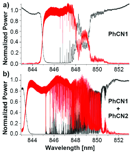
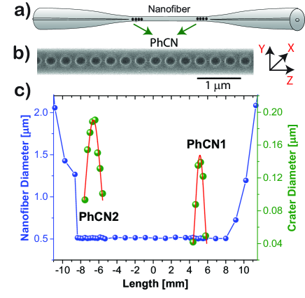
Figure 1(a) shows the schematic diagram of the nanofiber cavity. The nanofiber is fabricated by tapering a standard single mode optical fiber using heat-and-pull technique taper1 . The nanofiber is located at the waist of the tapered optical fiber. In order to extend the nanofiber length from few millimeters to few centimeters, we implement the linearly increasing hot-zone technique taper1 . The profile of the tapered fiber and the pulling parameters are designed based on the adiabatic tapering guidelines detailed in ref. adiabatic ; taper1 . By optimizing the parameters we have realized 99 transmission for tapered fibers with a total length of 7 to 8 cm, with a nanofiber waist diameter of 500 nm and waist length of 1.5 to 2.5 cm. The uniformity of the diameter over the entire length of the nanofiber is 2 nm which is measured using a nondestructive and in situ method detailed in ref. diameter . The photonic crystal structures are fabricated at the two ends of the nanofiber using the femtosecond laser ablation phcn1 ; phcn2 , thus forming a long nanofiber cavity. The scanning electron microscope image of a typical part of the PhCN is shown in Fig. 1(b). One can see that periodic nano-crater structures with a period of 350 nm are fabricated on the nanofiber phcn1 ; phcn2 . Figure 1(c) shows the diameter profile of a long nanofiber cavity whose optical properties are discussed in the following paragraphs. It shows the diameter profile of the nanofiber (blue circles) and that of the nano-craters (green circles) fabricated on it. The nanofiber diameter is 500 nm and it is uniform over a length of 1.7 cm. The two PhC structures (indicated as PhCN1 and PhCN2) are fabricated on the nanofiber with a separation of 1.2 cm. The PhCN1 is fabricated first and the PhCN2 is fabricated later. Each PhCN structure consists of thousands of periodic nano-craters phcn1 ; phcn2 . The diameter profiles of the nano-craters show a peak-like structure. The diameters at the peak of the profiles for the PhCN1 and PhCN2 are 140 nm and 190 nm, respectively. The red curves show the Gaussian fits to the diameter profiles yielding the 1/e2-widths of 0.9 mm and 1.7 mm for the PhCN1 and PhCN2, respectively. This suggests that the second fabrication was stronger than the first one.
The transmission and reflection spectra of the long nanofiber cavity are measured using a tunable, narrow linewidth diode laser (Newport TLB6700). The laser is coupled to the tapered fiber through a 99:1 fiber-inline beam splitter. The input light is launched through the 1% port and the transmission is measured after the tapered fiber, whereas the reflection is measured through the 99% port in the reverse direction. The spectra are recorded by monitoring the power in the transmission and reflection ports using photodiodes while the laser frequency is being scanned. The polarization control is achieved using a fiber-inline polarizer before the tapered fiber. Figure 2(a) shows the transmission (black curve) and reflection (red curve) spectra after the fabrication of the PhCN1 for the polarization perpendicular to the nano-crater faces (X-pol). One can see that the stopband extends over 845 nm to 848 nm, where the light is strongly reflected back. Also one can notice that sharp cavity modes appear in the red-side of the stopband. The mode spacing is 95.5 GHz corresponding to a cavity length of 1.3 mm. As discussed in the ref. phcn1 ; phcn2 , those cavity modes are due to the apodized index variation along the PhCN1. Figure 2(b) shows the transmission (black curve) and reflection (red curve) spectra after the fabrication of both the PhCN1 and PhCN2. One can see that the width of the stopband increased and extends over 844 nm to 850 nm. Moreover many closely spaced cavity modes appeared. This suggests that the second fabrication was stronger and confirms proper overlap between the stopbands of PhCN1 and PhCN2 to form a long nanofiber cavity.
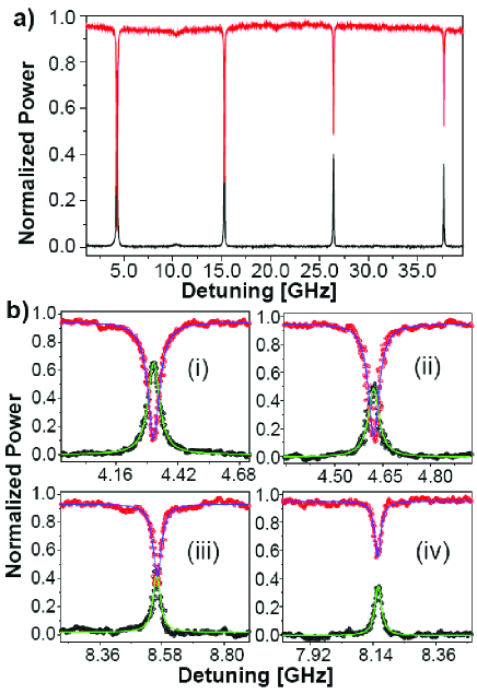
In order to properly resolve the cavity modes and precise normalization of the on-resonance transmission and reflection values, we use a CW Ti-sapphire laser source (MBR-110, Coherent Inc.). In this measurement the laser frequency is locked to a reference cavity and the linewidth is 100 kHz. The spectra are recorded by monitoring the power in the transmission and reflection ports while stretching the tapered fiber. The details of such a technique was reported in ref.phcn2 . Although we chose this method to be more reliable, we must mention that the spectra measured using laser frequency scanning technique yielded similar results with only marginal differences. A typical part of the transmission (black curve) and reflection (red curve) spectra for X-pol is shown in Fig. 3(a). One can see periodically spaced sharp cavity modes. The mode spacing () is 10.36 GHz. From the value we estimate a cavity length () of 1.2 cm, where (1.2) is the effective index of the nanofiber guided mode. Four typical cavity modes are shown individually in Fig. 3(b). The data for the measured transmission and reflection spectra for the cavity modes are shown in black and red circles, respectively. The green and blue curves show the Lorentzian fits. The linewidths () for the modes marked as i, ii, iii and iv are 59, 41, 33 and 27 MHz corresponding to the finesse () values of 175, 252, 314 and 384, respectively. One can notice that the on-resonance transmission () and reflection () is increasing and decreasing, respectively as the cavity linewidth is increased.
The amplitudes of the field transmission () and reflection () of a two-sided cavity can be formulated milburn as
| (1) |
where is the detuning between the laser frequency and the cavity resonance, is the intra-cavity loss rate, and are the coupling rates of the input and output side mirrors, respectively and is the cavity linewidth. The power transmission () and reflection () from the cavity are given by and . Assuming a symmetric cavity () the on-resonance () transmission and reflection can be written as
| (2) |
From the above equation it is clear that the and values will increase and decrease, respectively as the increases. Moreover, when the and values are equal, the total out coupling rate () and the intra-cavity loss rate () balance each other and one can get .
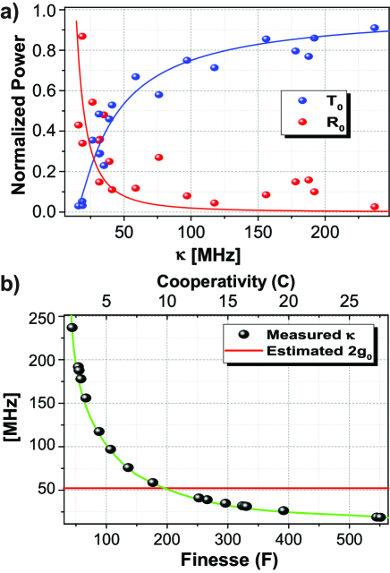
Figure 4(a) shows the (blue circles) and (red circles) values for the selected cavity modes (along with the modes shown in Fig. 3(b)) plotted against the corresponding values. In the selection process we have chosen the cavity modes that have the highest transmission for the corresponding values. The blue and red lines are the fits using Eq. 2. From the fits we estimate the lowest value to be 151 MHz. Also one can clearly see from the plot that the and values are equal around 30 MHz. From this value, we estimate the one-pass intra-cavity transmission to be 99.53%. We have fabricated several cavity samples and measured the lowest value to be in the range 15 - 20 MHz. This suggests that the fabrication process is reproducible. We must mention that we have also measured the cavity characteristics for the orthogonal polarization (Y-pol). We have found that the cavity transmission for Y-pol is smaller compared to the X-pol, resulting in higher value.
Based on the optical characteristics of the cavity we now estimate the potential of the cavity in the context of cavity QED and quantum information application. Figure 4(b) summaries the measured values corresponding to the values. The estimated and values are also shown assuming a single Cs-atom trapped 200 nm away from the fiber surface famsan2 . This shows that for the measured cavity modes we can achieve high cooperativity ranging from 3 to 25. For cavity modes having values smaller than 50 MHz (i.e. finesse in the range 200 to 400), ”strong-coupling” regime can be realized. As shown in Fig. 4(a), the on-resonance transmission for such cavity modes can be as high as 40 to 60. On the other hand, for the cavity modes having values between 50 MHz to 170 MHz, the on-resonance transmission range from 60 to 85, while maintaining a cooperativity of 3-10. We must mention that using solid-state quantum emitters like quantum dot or color centers in nanodiamonds, the emitter can be placed directly on the nanofiber surface leading to much higher cooperativity in the range 15-50 famsan2 . Hence such cavity modes can be implemented for fiber-based single photon sources and quantum nonlinear optics in ”Purcell” regime.
In conclusion, we have demonstrated the fabrication of a 1.7 cm long nanofiber with highly uniform diameter of 500 2 nm over the entire length and maintaining high transmission of 99%. Furthermore, we fabricate two photonic crystal structures separated by 1.2 cm on such a nanofiber using femtosecond laser ablation, thus forming a centimeter-long nanofiber cavity. The high optical quality of such a cavity shows promising avenues for fiber-based quantum interface and single photon sources.
This work was supported by the Japan Science and Technology Agency (JST) as one of the Strategic Innovation projects. KPN acknowledges support from a grant-in-aid for scientific research (Grant no. 15H05462) from the Japan Society for the Promotion of Science (JSPS).
References
- (1) H. J. Kimble, “The quantum internet,” Nature 453, 1023-1030 (2008).
- (2) P. Berman, Cavity Quantum Electrodynamics (Academic Press, Boston, 1994).
- (3) A. Reiserer and G. Rempe, “Cavity-based quantum networks with single atoms and optical photons,” Rev. Mod. Phys. 87, 1379-1418 (2015).
- (4) J. McKeever, A. Boca, A. D. Boozer, J. R. Buck, and H. J. Kimble, “Experimental realization of a one-atom laser in the regime of strong coupling,” Nature 425, 268-271 (2003).
- (5) A. Boca, R. Miller, K. M. Birnbaum, A. D. Boozer, J. McKeever, and H. J. Kimble, “Observation of the vacuum Rabi spectrum for one trapped atom,” Phys. Rev. Lett. 93, 233603 (2004).
- (6) P. Maunz, T. Puppe, I. Schuster, N. Syassen, P. W. H. Pinkse, and G. Rempe, “Cavity cooling of a single atom,” Nature 428, 50-52 (2004).
- (7) T. G. Tiecke, J. D. Thompson, N. P. de Leon, L. R. Liu, V. Vuletić, and M. D. Lukin, “Nanophotonic quantum phase switch with a single atom,” Nature 508, 241-244 (2014).
- (8) F. L. Kien and K. Hakuta, “Cavity-enhanced channeling of emission from an atom into a nanofiber,” Phys. Rev. A 80, 053826 (2009).
- (9) J. D. Love, W. M. Henry, W. J. Stewart, R. J. Black, S. Lacroix, and F. Gonthier, “Tapered single-mode fibres and devices. Part 1: Adiabaticity criteria,” IEE Proc. 138, 343-354 (1991)
- (10) J. E. Hoffman, S. Ravets, J.A. Grover, P. Solano, P. R. Kordell, J. D. Wong-Campos, L. A. Orozco, S. L. Rolston, “Ultrahigh transmission optical nanofibers,” AIP Advances 4, 067124 (2014).
- (11) K. P. Nayak, F. L. Kien, Y. Kawai, K. Hakuta, K. Nakajima, H. T. Miyazaki, and Y. Sugimoto, “Cavity formation on an optical nanofiber using focused ion beam milling technique,” Opt. Express 19, 14040-14050 (2011).
- (12) K. P. Nayak and K. Hakuta, “Photonic crystal formation on optical nanofibers using femtosecond laser ablation technique,” Opt. Express 21, 2480-2490 (2013).
- (13) K. P. Nayak, P. Zhang, and K. Hakuta, “Optical nanofiber-based photonic crystal cavity,” Opt. Lett. 39, 232-235 (2014).
- (14) M. Sadgrove, R. Yalla, K. P. Nayak, and K. Hakuta, “Photonic crystal nanofiber using an external grating,” Opt. Lett. 38, 2542-2545 (2013).
- (15) R. Yalla, M. Sadgrove, K. P. Nayak, and K. Hakuta, “Cavity quantum electrodynamics on a nanofiber using a composite photonic crystal cavity,” Phys. Rev. Lett. 113, 143601 (2014).
- (16) C. Wuttke, M. Becker, S. Brückner, M. Rothhardt, and A. Rauschenbeutel, “Nanofiber fabry-perot microresonator for nonlinear optics and cavity quantum electrodynamics,” Opt. Lett. 37, 1949–1951 (2012).
- (17) S. Kato and T. Aoki, “Strong coupling between a trapped single atom and an all-fiber cavity,” Phys. Rev. Lett. 115, 093603 (2015).
- (18) T. A. Birks and Y. W. Li, “Shape of fiber tapers,” Journal of Lightwave Technology 10, 432 (1992).
- (19) J. Keloth, M. Sadgrove, R. Yalla, and K. Hakuta, “Diameter measurement of optical nanofibers using a composite photonic crystal cavity,” Opt. Lett. 40, 4122-4125 (2015).
- (20) D. F. Walls and G. J. Milburn, Quantum Optics (Springer, Berlin, 2008).