Time-reversal symmetry breaking hidden order in Sr2(Ir,Rh)O4
Abstract
Layered 5 transition iridium oxides, Sr2(Ir,Rh)O4, are described as unconventional Mott insulators with strong spin-orbit coupling. The undoped compound, Sr2IrO4, is a nearly ideal two-dimensional pseudospin- Heisenberg antiferromagnet, similarly to the insulating parent compound of high-temperature superconducting copper oxides. Using polarized neutron diffraction, we here report a hidden magnetic order in pure and doped Sr2(Ir,Rh)O4, distinct from the usual antiferromagnetic pseudo-spin ordering. We find that time-reversal symmetry is broken while the lattice translation invariance is preserved in the hidden order phase. The onset temperature matches that of the odd-parity hidden order recently highlighted using optical second harmonic generation experiments. The novel magnetic order and broken symmetries can be explained by the loop-current model, previously predicted for the copper oxide superconductors.
Laboratoire Léon Brillouin, CEA-CNRS, Université Paris-Saclay, CEA Saclay, 91191 Gif-sur-Yvette, France
Laboratoire de Physique des Solides, Université Paris-Sud, Université Paris-Saclay, 91405 Orsay, France
In the layered perovskite material, Sr2IrO4, spin-orbit coupling and strong electron correlations combine to give rise to a spin-orbit coupled Mott insulator with a pseudo-spin antiferromagnetic (AFM) state [1, 2]. It exhibits close structural [3, 4], electronic [5, 6] and magnetic [3, 4] similarities with the layered perovskite material, La2CuO4, which evolves from a spin antiferromagnetic Mott insulator to a high temperature superconductor upon doping. Doped Sr2IrO4 has then become a quite promising material to discover new states of matter, including unconventional superconductivity.
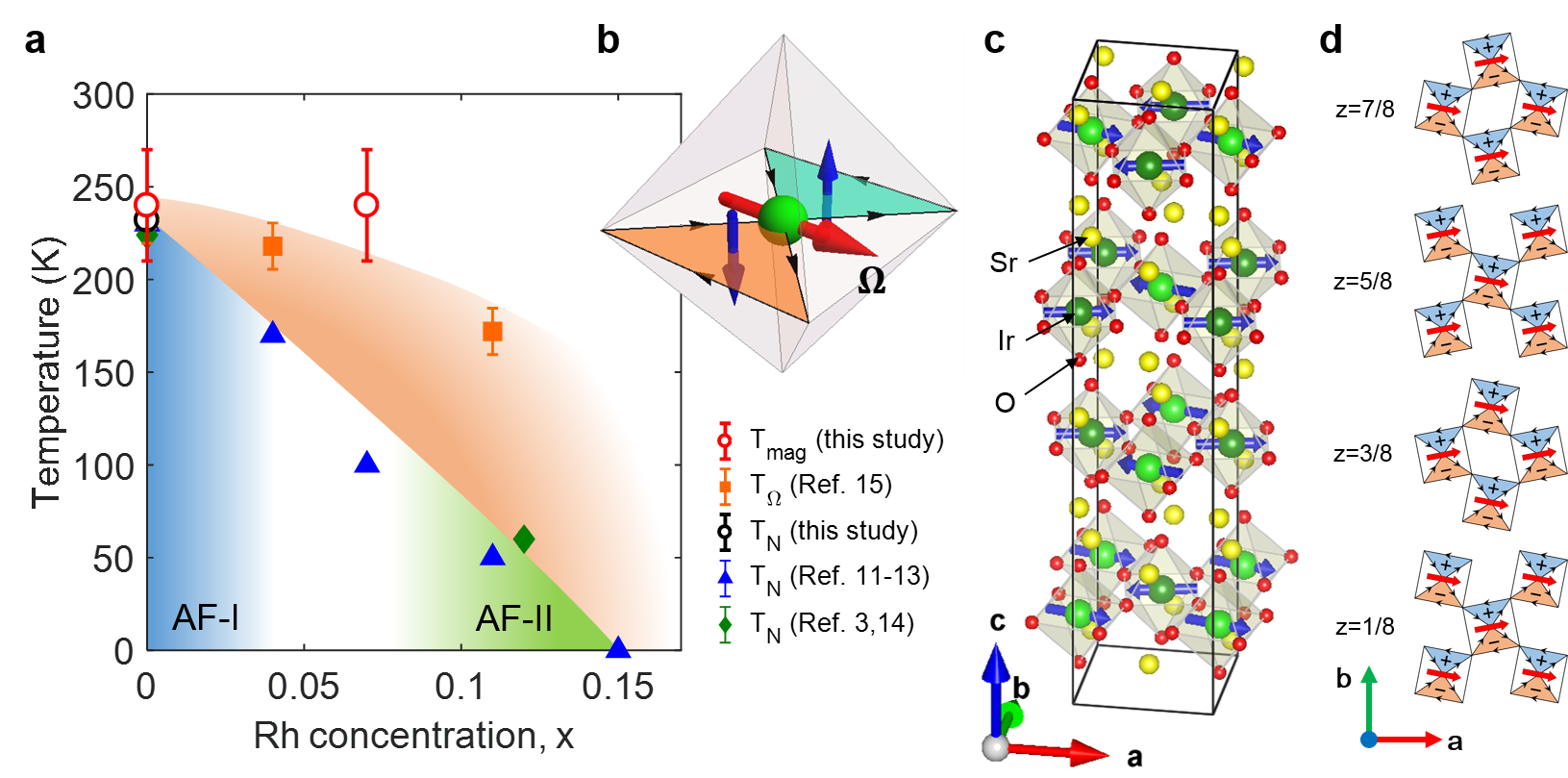
The crystal structure of the layered perovskite Sr2IrO4 is characterized by the stacking of IrO2 and SrO layers. The Ir4+ ion is at the center of an oxygen octahedron, rotated by in the basal plane. (Fig. 1c). For a long time, Sr2IrO4 has been described as possessing a tetragonal centrosymmetric structure with four-fold rotational symmetry about the -axis, corresponding to a space group [7]. However, a structural distortion exists even above room temperature as shown by optical second harmonic generation studies [8] yielding to the space group where the - and -glide planes are lost. That gives rise to additional weak Bragg spots such as that have been reported using neutron diffraction [3, 4]. In this material, crystal field effects, spin-orbit coupling, Coulomb repulsion and the bending of the Ir-O-Ir bonds play an important role to understand electronic and magnetic properties.
Within the octahedral crystal field, the Ir electronic levels split into eg and t2g states. Under strong spin-orbit coupling, the t2g states split into a doublet and quartet, so that, among the five electrons of the Ir4+ ion, only one remains in the doublet state. A large enough effective Coulomb repulsion finally localizes the electron and one is left with a pseudo-spin model. Below 230 K [1], an AFM order develops, characterized by a magnetic propagation wavevector and magnetic moments at the Ir sites aligned in the basal -plane [3, 4, 9] (Fig. 1c). The directions of the staggered magnetic moments are tied to IrO6 octaedra and follow their rotation, , giving rise to a canting of the AFM structure in each IrO2 layer with a ferromagnetic component along the -axis. As shown in Fig. 1c, the magnetic structure of Sr2IrO4 has a staggered stacking along the -axis of the canted AFM layers (defined as or depending of the sign of the tilt). In other words, the weak ferromagnetic component in each layer is stacked to give a structure along -axis (AF-I phase) [3, 4], so it cancels out globally. However, the AFM interaction along the -axis is rather weak, thus it is easily transformed to the stacking order (AF-II phase) by applying an external magnetic field [2]. At variance with the AF-I order, the AF-II stacking is then characterized by a magnetic propagation vector [10] and a net (but weak) ferromagnetic moment. Thorough that paper, we refer to these AFM phases, as the one depicted in Fig. 1c, as conventional AFM phases.
Interestingly, the AFM transition temperature is suppressed under the substitution of Rh for Ir. While the Rh substitution could be thought to be iso-electronic, it should be stressed that Rh is likely to play the role of an acceptor (Rh3+/Ir5+) and effectively give rise to a hole-doping of the material [10]. Fig. 1a shows the magnetic phase diagram in Sr2Ir1-xRhxO4. From bulk magnetization [12, 13, 11] and neutron diffraction measurements [3, 14], the conventional AFM transition decays almost linearly as a function of Rh substitution up to . Actually, x-ray studies [10] indicate a slightly larger critical doping with the occurence of another transition at lower temperature when the magnetic correlation lengths are effectively diverging. Further, upon Rh-substitution, the AFM order undergoes a transition from the AF-I to the AF-II phase, even at zero magnetic field [10, 14].
Recently, a hidden broken symmetry phase, developing prior to the AFM state, has been reported in Sr2(Ir,Rh)O4 using rotational anisotropy optical second harmonic generation (SHG) measurements [15]. The hidden broken symmetry phase was observed distinctively at a few K above for the pure sample, and far above for the doped systems [15]. These data highlight an odd-parity hidden order as both the inversion and four-fold rotational symmetries are broken below a temperature distinct from the Néel temperature (Fig. 1a) [15]. From the symmetry analysis, the SHG results could be in principle explained by a triclinic distortion of the crystal structure. However there is no experimental evidence using x-ray and neutron scattering of any structural distortion [2, 3, 4]. It should be nevertheless stressed that these diffraction studies use too modest spatial resolution to definitively prove a lack of symmetry lowering.
Alternatively, the SHG signal could be due to a magnetic ordering although there is no proof of time-reversal symmetry breaking at . Actually, the AF-I ground state of pure Sr2IrO4 preserves the parity inversion symmetry and thus cannot explain the SHG signal. Instead, a few magnetic point groups that preserve the translation symmetry of the lattice were proposed to account for the SHG signal, such as or [15, 16]. In particular, a so-far non-observed AFM state of symmetry, corresponding to a stacking along the axis of AFM planes, would produce the SHG signal [16].
Among the magnetic point groups, it is argued [15] that the new broken symmetries can be caused by a loop current (LC) phase [17, 18], theoretically proposed to account for the pseudo-gap physics of superconducting cuprates. The existence of such a magneto-electric state has gained support from the detection in several cuprate families of its magnetic fingerprint by polarized neutron diffraction [19, 20, 21, 22, 23]. Using the same technique for Sr2(Ir,Rh)O4, we here report at the temperature of the odd-parity order, , the appearance of a hidden magnetic order, which breaks time reversal symmetry while preserving lattice translation invariance. Among the magnetic models inferred from the SHG data [15], only the co-planar LC order [17, 18] produces a magnetic diffraction pattern consistent with our polarized neutron data. Our results show that exotic magnetic orders with the same symmetry properties as the LC phase exist in both iridates and cuprates.
Results
Let us first describe the co-planar loop current order. It is characterized by two circulating currents turning clockwise and anti-clockwise within the same plane inside the IrO6 octahedron (Fig. 1b), and belongs to a point group symmetry. It breaks time-reversal and inversion symmetries but not their product. The LCs produce two opposite orbital magnetic moments within each IrO6 octahedron. A toroidal pseudo-vector, or anapole, is defined as an order parameter by , where and stand for the position and the orbital magnetic moment, respectively, in one octahedron (Fig. 1b). It is similar to the toroidal moment in multiferroic systems [24]. When the anapole vectors are parallel along the -axis (ferro-toroidal coupling) as shown in Fig. 1d, the ordered structure does not break translational symmetry but breaks parity inversion and four-fold rotational symmetries [15]. Since the direction of the anapole is bound to the orientation of each IrO6 octahedron, the resulting order is a nearly-ferro-toroidal order (i.e. weakly distorted) (Fig. 1d).
As explained in the Supplementary Note 1, the Fourier transform of the magnetic correlation function associated with the LC phase is located in iridates at nuclear Bragg peaks, such as . These Bragg peaks respect both the original body-centered tetragonal structure condition and the condition due to the translation. (The wave-vector is denoted by , see Method). This produces a very specific magnetic diffraction pattern, which can be probed by magnetic sensitive diffraction technique, such as neutron scattering technique.
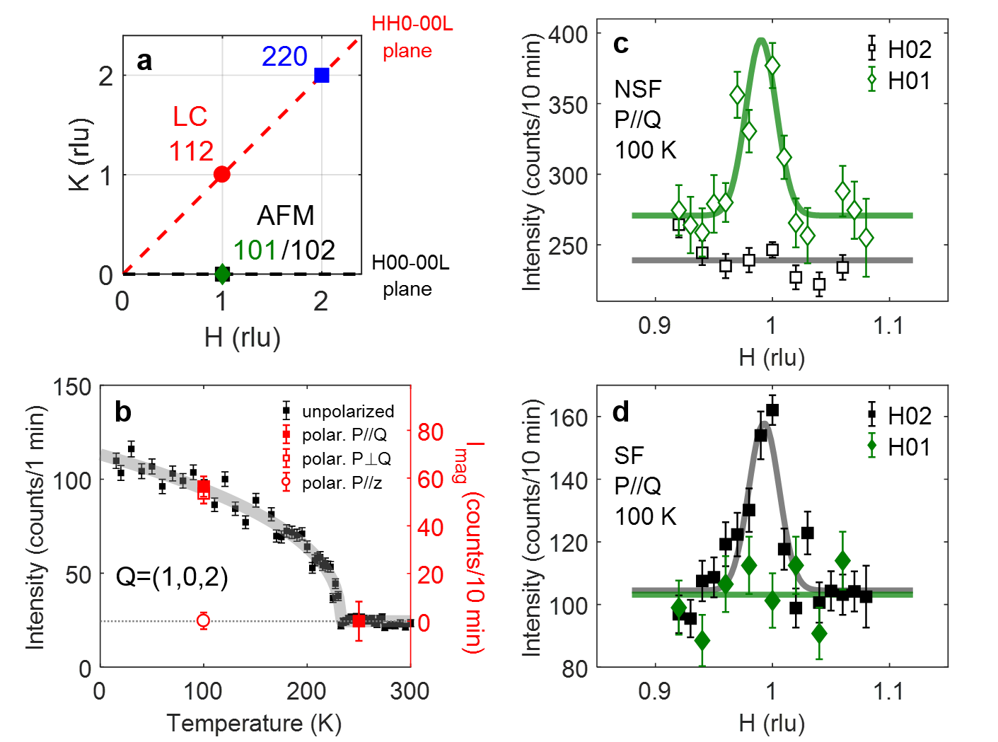
We have investigated both the conventional AFM orders and the LC magnetic order using neutron scattering diffraction experiments. Note that the momentum transfers are different for both types of phase: for AFM peaks and for the LC peaks (see Supplementary Note 1). Three major wave-vectors positions, , have been examined: their projection onto the reciprocal -plane are shown in Fig. 2a. We have then studied each phase in a different scattering plane: - for conventional AFM orders and - to study LC order (see Method). We have investigated two iridate samples: a pure Sr2IrO4 and a 7% Rh-doped one. Small single crystals have been co-aligned to get a large enough sample mass in order to perform the polarized neutron experiment. The Supplementary Note 2 describes the sample preparation and shows magnetization measurements, which characterize the samples.
We have first studied the conventional AF-II order by repeating unpolarized neutron diffraction measurements [3, 4]. We report in Fig. 2b the AFM Bragg peak at in the pure system where the magnetic Bragg intensity shows a sharp AFM transition at K. The fitted critical exponent is consistent to 0.36 in the previous report [3]. Next, we have performed polarized neutron experiment to study the Bragg peaks to disentangle the magnetic and nuclear contributions of these peaks. The polarized neutron experiment setup is presented in the Supplementary Note 3. It has been already used in previous measurements in cuprates and described in Refs. [19, 20, 21, 22, 23]. For a given neutron polarization , the neutron intensities, and , are measured in both spin-flip (SF) and non-spin-flip (NSF) channels, respectively. Full magnetic signal appears in the SF channel when [21, 23] whereas the nuclear intensity occurs in the NSF chanel. The Fig. 2c,d shows the wave-vector scans along across the magnetic peak for the NSF and SF channels. That proves the magnetic origin of the peak as it is only seen in the SF channel (Fig. 2d). In Fig. 2b, the magnetic intensity is determined at two temperatures, 100 K and 250 K, below and above (where stands for the flat background of Fig. 2d). A clear magnetic intensity is sizeable at 100 K, whereas no magnetic intensity is seen at 250 K. Further, we report at 100 K in Fig. 2b the magnetic intensity for three different neutron polarization states: the polarizations and are in the scattering plane (see Method), whereas is perpendicular to the scattering plane. In the given geometry, zero magnetic intensity with proves that the AFM moments are confined in the -plane. This is in agreement with the previous studies of the neutron structure factors [3, 4].
In the same scattering plane, the Bragg peaks at for and were also measured using polarized neutron. They correspond to the forbidden peaks of the original structure giving rise to the space group where the glide planes are lost [8]. As it has been already discussed [3, 4], their temperature dependence exhibits no anomaly neither at the Néel temperature nor at the onset of the odd-parity hidden order () [15]. The origin of that scattering is non-magnetic, as shown in Fig. 2c,d. For the Bragg peak at , no signal is sizeable in the SF channel and only a NSF signal is observed above the background. These results exclude the possibility of an AFM arrangement of type, where the magnetic signal should be only at odd -value. It casts serious doubts that such an AFM stacking can explain the origin of the SHG signal [16]. The same conclusion holds for the arrangement, not observed in pure Sr2IrO4, in full agreement with the literature [3, 4, 9]. To account for the occurrence of an odd-parity hidden order in SHG measurements in pure Sr2IrO4, we are left with two scenarii. Either, the missing AFM orders are light-induced metastable states during the SHG measurements, as suggested in Ref. 16, or another kind of magnetic order exists. Let us consider now this second scenario.
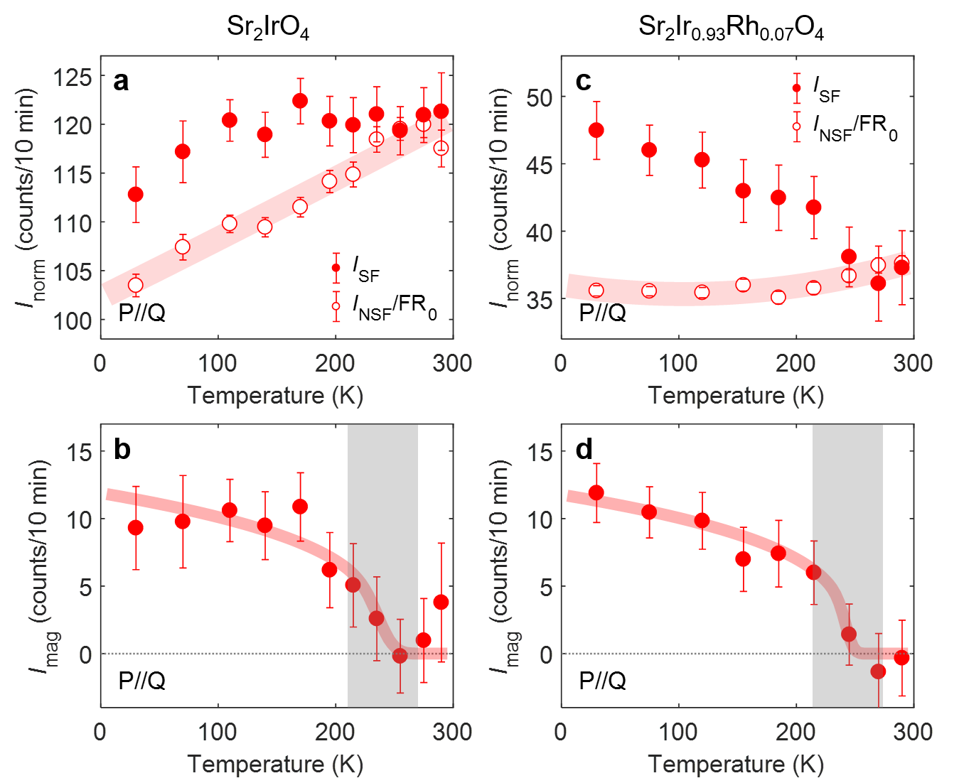
The overall experimental procedure to extract the magnetic signal associated with the LC order is detailed in the Supplementary Note 4 and it follows methods established in previous works on superconducting cuprates [19, 21]. The measured spin-flip intensity, , is reported as a function of temperature in Fig. 3a for the pure sample. It is compared with the background baseline determined from the measured NSF intensity (see the Fig. 3a caption and Supplementary Note 4). While decreases monotonically as temperature decreases, the SF intensity instead departs from below K. The difference, , evidences a spontaneous magnetic order whose magnetic intensity, , is reported in Fig. 3b. It has a different symmetry compared to the conventional AFM phases discussed above and the position corresponds to where magnetic intensity is expected for the LC phase. For the 7% Rh-substituted sample, the same analysis is given in Fig. 3c and d. While the AFM transition is suppressed down to K, the novel magnetic order is observed at much higher temperature K. Within error bars, the transition temperature, and its normalized magnetic intensity do not show a significant difference between the pure system and 7% Rh-substitution. This is consistent with the estimate of onset of the hidden order, , from SHG (orange squares in Fig. 1a) [15], which does not change appreciably with Rh substitution. Using the calibration of nuclear Bragg peaks intensities, one can deduce the magnetic cross section of the hidden magnetic order as mbarns/f.u., which is less than of the strongest nuclear Bragg peak. The normalized magnitude of for the hidden magnetic order is similar in both samples and is times smaller than the one for the AFM order, as shown in Fig. 3.
Discussion
To understand the spontaneous magnetic order at , a model is needed to explain the broken symmetries of the hidden order. Concomitant with the SHG data, time-reversal, parity inversion and 4-fold rotational symmetries are broken. It preserves the translational symmetry of the underlying lattice, as the magnetic scattering appears on top of the nuclear Bragg peak. The loop-current model [17, 18] is a good candidate, since it can explain all these broken symmetries. Nevertheless, more detailed and quantitative study is required to establish the exact order parameter in the hidden ordered phase. The weak magnetic cross section shows how difficult it is to detect and why it was not reported with typical unpolarized neutron diffraction. Due to the experimental limitations, a precise determination of the direction of induced magnetic moments and magnetic structure requires further works.
Actually, other magnetic orders, which could potentially account for the SHG data, are not consistent with our finding as they would give rise to distinct scattering patterns. For instance, the proposed structure with point group [15] yields a different relation , as the configuration is opposite when one considers the translation. This breaks the original body-centered nuclear structure [7], and would give rise to magnetic superstructure peaks at and no magnetic intensity at any position. With Rh doping, one also does not observe magnetic superstructures at with even [10, 14]. Both points dismiss the proposal of the point group [15].
Alternatively, the SHG measurements have been re-interpreted considering conventional AFM orders [16] with a different stacking along the -axis. We detail in the Supplementary Note 5 why the different AFM structures discussed in the literature cannot actually explain our observation. First, since the hidden order occurs at different positions compared to the AFM order, it is clearly distinct with the AF-I order. Second, the AFM state of symmetry with a stacking along the -axis of AFM planes is argued to explain SHG data [16]. This phase will give rise to magnetic contributions at positions such as and nothing at , where we observe the hidden magnetic intensity. Further, the non-magnetoelectric phase (AF-II) (described above) could also account for the SHG data [16]. This AF-II phase is reported in the Rh-doped system [10, 14] but is absent in the pure system [3, 4]. It would also exhibit the largest magnetic contribution at as well as tiny magnetic contributions at Bragg peaks, such as , due to its weak ferromagnetism. This interpretation can be excluded in both samples we have studied. First, in the pure sample, the ferromagnetic order is absent (see Fig. 1) [3, 4] and can be only induced by an applied magnetic field of about 0.2 T (2000 Oe) [2]. Second, under Rh substitution, such a ferromagnetic order indeed develops, but only below [10], as it results from the canting of the AFM order, clearly lower than . Moreover, the neutron intensity due to ferromagnetism would be smaller than the AFM one, i.e at least one order of magnitude smaller than the observed magnetic scattering we report here. All these arguments allow us to rule out the weak ferromagnetism derived from the canted AFM order as a candidate to account for the observed magnetic scattering at . Therefore, our observation of a magnetic signal at is not consistent with any kind of stackings along the -axis of the pseudo-spin AFM orders considered to explain the SHG signal in Ref. [16].
Using polarized neutron diffraction, we have experimentally addressed all these alternative phases and found out evidence for a hidden magnetic order in Sr2Ir1-xRhxO4. It is a translation-invariant but time-reversal symmetry broken phase that is consistent with the LC order of point group symmetry, concomitantly compatible with the SHG signal. In that model, all IrO6 octahedra, which are the building blocks of the material, are identically decorated by the same set of staggered magnetic moments, whose magnetism cancels out on each octahedron (as depicted in Fig. 1b). This magnetic order is then clearly distinct from the AFM one, where each octahedron has a single pseudo-spin on the Ir site and where the nearest octahedra have staggered moments.
In conclusion, we report the first evidence of an unconventional magnetic order in Sr2(Ir,Rh)O4, which breaks time-reversal symmetry but preserves translational symmetry of the underlying lattice. By analogy with superconducting cuprates, where a similar kind of order is observed, one can refer to it as an intra-unit-cell order. The new magnetic phase overlaps with parity inversion and rotational symmetry broken phase recently reported using SHG [15]. Both observations can be described by the loop-current order [17, 18] proposed for the pseudogap state in cuprates, where it is well supported by polarized neutron measurements [19, 21]. Further, the neutron observation in cuprates is confirmed as well by recent SHG measurements that show a global broken inversion symmetry in YBa2Cu3O6+x [25]. This may provide more analogy between the iridates and the high- cuprates, in spite of a different nature of and orbitals. A noticeable difference is here that the loop order occurs in the insulating compounds at half-filling, whereas in cuprates it is observed in the doped metallic (superconducting) state. Our report generalizes the existence of loop-current electronic states in oxides.
Methods: Polarized neutron diffraction
The polarized neutron experiments were performed on the triple axis spectrometer 4F1 (Orphée, Saclay, France) (see Supplementary Note 3). All measurements were done in two different scattering planes, either - or -, where the scattering wave-vector is quoted as with Å-1 and Å-1. As emphasized in Supplementary Note 1, in Sr2(Ir,Rh)O4, the conventional AFM order is expected in the - plane and the LC phase in the - plane. For each wave-vector , the scattered intensity is measured in both spin-flip (SF) and non-spin-flip (NSF) channels. The neutron measurements have been performed with a neutron polarization where the magnetic signal appears entirely in the SF channel [19, 21]. The AF-I order was further studied with a polarization (but still within the - plane) as well as with a polarization which is perpendicular to the scattering plane (along in the given case). The Sr2(Ir,Rh)O4 single crystals preparation and caracterization are described in the Supplementary Note 2.
We wish to thank S. Di Matteo, D. Hsieh, B.J. Kim, M.R. Norman and C.M. Varma for fruitful discussions. We also acknowledge financial supports from the projects NirvAna (contract ANR-14-OHRI-0010) and SOCRATE (ANR-15-CE30-0009-01) of the ANR French agency.
The authors declare that they have no competing financial interests.
Correspondence and requests for materials should be addressed to Jaehong Jeong (email: jaehong.jeong@cea.fr) or Philippe Bourges (email: philippe.bourges@cea.fr).
References
- [1] Kim, B. et al. Novel Jeff= Mott state induced by relativistic spin-orbit coupling in Sr2IrO4. Physical Review Letters 101, 076402 (2008).
- [2] Kim, B. et al. Phase-sensitive observation of a spin-orbital Mott state in Sr2IrO4. Science 323, 1329–1332 (2009).
- [3] Ye, F. et al. Magnetic and crystal structures of Sr2IrO4: A neutron diffraction study. Physical Review B 87, 140406 (2013).
- [4] Dhital, C. et al. Neutron scattering study of correlated phase behavior in Sr2IrO4. Physical Review B 87, 144405 (2013).
- [5] Wang, F. & Senthil, T. Twisted Hubbard model for Sr2IrO4: magnetism and possible high temperature superconductivity. Physical Review Letters 106, 136402 (2011).
- [6] Arita, R., Kuneš, J., Kozhevnikov, A., Eguiluz, A. & Imada, M. Ab initio studies on the interplay between spin-orbit interaction and Coulomb correlation in Sr2IrO4 and Ba2IrO4. Physical Review Letters 108, 086403 (2012).
- [7] Huang, Q. et al. Neutron powder diffraction study of the crystal structures of Sr2RuO4 and Sr2IrO4 at room temperature and at 10 K. Journal of Solid State Chemistry 112, 355–361 (1994).
- [8] Torchinsky, D. et al. Structural distortion-induced magnetoelastic locking in Sr2IrO4 revealed through nonlinear optical harmonic generation. Physical Review Letters 114, 096404 (2015).
- [9] Boseggia, S. et al. Robustness of basal-plane antiferromagnetic order and the state in single-layer iridate spin-orbit Mott insulators. Physical Review Letters 110, 117207 (2013).
- [10] Clancy, J. et al. Dilute magnetism and spin-orbital percolation effects in Sr2Ir1-xRhxO4. Physical Review B 89, 054409 (2014).
- [11] Brouet, V. Private communication (2016).
- [12] Qi, T. et al. Spin-orbit tuned metal-insulator transitions in single-crystal Sr2Ir1-xRhxO4 . Physical Review B 86, 125105 (2012).
- [13] Cao, Y. et al. Hallmarks of the Mott-metal crossover in the hole-doped pseudospin-1/2 Mott insulator Sr2IrO4. Nature Communications 7, 11367 (2016).
- [14] Ye, F. et al. Structure symmetry determination and magnetic evolution in Sr2Ir1-xRhxO4. Physical Review B 92, 201112 (2015).
- [15] Zhao, L. et al. Evidence of an odd-parity hidden order in a spin-orbit coupled correlated iridate. Nature Physics 12, 32–36 (2016).
- [16] Di Matteo, S. & Norman, M. R. Magnetic ground state of Sr2IrO4 and implications for second-harmonic generation. Phys. Rev. B 94, 075148 (2016).
- [17] Varma, C. Non-Fermi-liquid states and pairing instability of a general model of copper oxide metals. Physical Review B 55, 14554 (1997).
- [18] Simon, M. & Varma, C. Detection and implications of a time-reversal breaking state in underdoped cuprates. Physical Review Letters 89, 247003 (2002).
- [19] Fauqué, B. et al. Magnetic order in the pseudogap phase of high- superconductors. Physical Review Letters 96, 197001 (2006).
- [20] Li, Y. et al. Unusual magnetic order in the pseudogap region of the superconductor HgBa2CuO4+δ. Nature 455, 372–375 (2008).
- [21] Bourges, P. & Sidis, Y. Novel magnetic order in the pseudogap state of high- copper oxides superconductors. Comptes Rendus Physique 12, 461–479 (2011).
- [22] Sidis, Y. & Bourges, P. Evidence for intra-unit-cell magnetic order in the pseudo-gap state of high- cuprates. Journal of Physics: Conference Series, 449, 012012 (IOP Publishing, 2013).
- [23] Mangin-Thro, L., Sidis, Y., Wildes, A. & Bourges, P. Intra-unit-cell magnetic correlations near optimal doping in YBa2Cu3O6.85. Nature Communications 6, 7705 (2015).
- [24] Spaldin, N. A., Fiebig, M., Mostovoy, M. The toroidal moment in condensed-matter physics and its relation to the magnetoelectric effect, J. Phys. Cond. Matt., 20, 434203 (2008).
- [25] Zhao, L., Belvin, C. A., Liang, R., Bonn, D. A., Hardy, W. N., Armitage, N. P. & Hsieh, D. A global inversion-symmetry-broken phase inside the pseudogap region of YBa2Cu3Oy, Nature Phys. 10.1038/nphys3962 (2016).
Supplementary Note 1
Reciprocal space comparison with cuprates
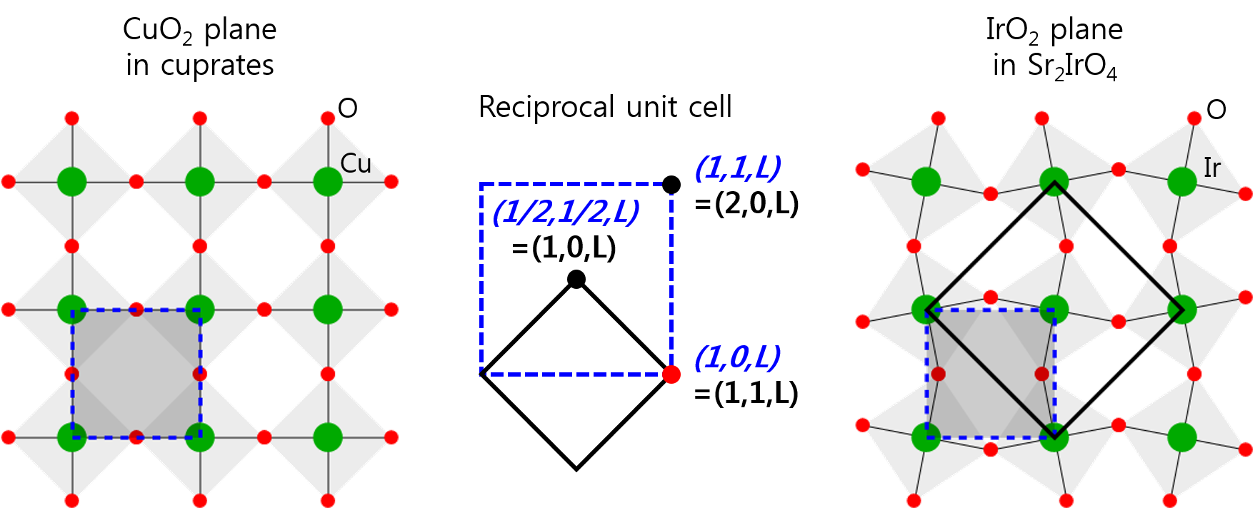
The Sr2IrO4 exhibits a very similar in-plane structure compared to superconducting cuprates. In cuprates, corner-shared CuO6 octahedra or CuO5 pyramids make a (nearly) square lattice of CuO2 plaquettes on the basal -plane. On the other hand in iridates, the IrO6 octahedra are also corner-shared but rotated by in the basal plane. Due to this in-plane rotation, the unit cell for iridates is doubled and rotated by 45∘ as shown in Fig. 4. Despite a difference between the spin of Cu2+ and pseudo-spin of Ir4+ states, the antiferromagnetic (AFM) structure is also almost the same in both systems, so the magnetic Bragg conditions are also similar. However, under the 45∘ unit-cell transformation, actual Miller indices are different. In the center of Fig. 4, we compare a few interesting Bragg -positions in the planar reciprocal -plane for iridates (black) and cuprates (blue). For instance, the for the AFM order in cuprates is transformed to or for iridates, and the in cuprates, where the loop-current (LC) order has been reported [1, 2], corresponds to for iridates.
Supplementary Note 2
Coaligned single crystals and magnetization measurements
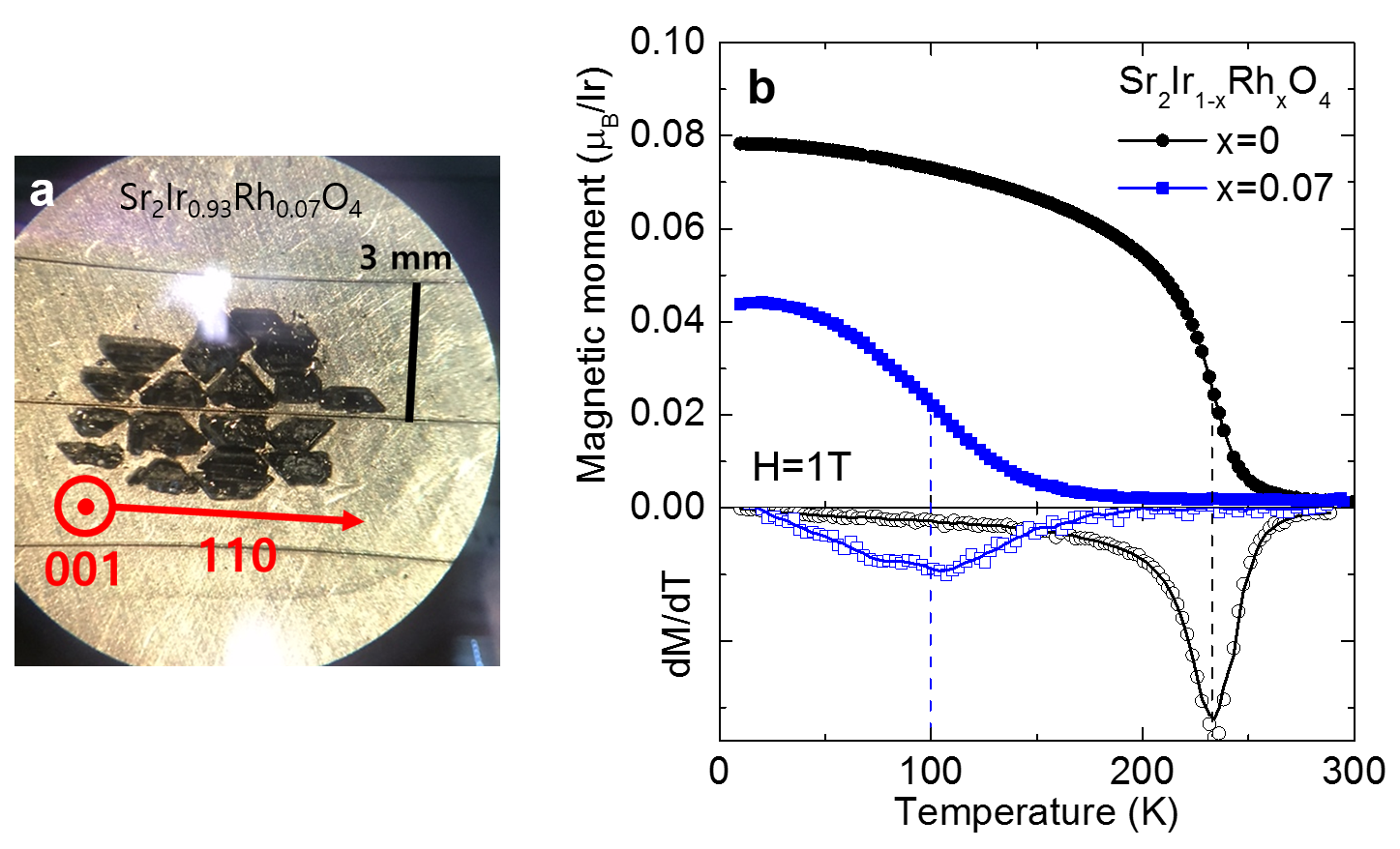
We have investigated the pure and 7% Rh-doped single crystals grown by flux method at Laboratoire de Physique des Solides (Orsay). Owing to a rectangular cuboid shape of the crystals, several tiny crystals could be coaligned in order to increase the total mass, as shown in Fig. 5a. To address the conventional antiferromagnetic (AFM) order, the magnetization was measured under a magnetic field T using Magnetic Property Measurement System (MPMS). The pure system originally exhibits an AFM order, but it can easily show ferromagnetism, by applying a small external magnetic field T (2000 Oe) [3]. For instance, the reported magnetic moment deduced from magnetization measurements shown in Fig. 5b corresponds to a net ferromagnetic moment under 1 T. This ferromagnetism originates from a canting of the AFM structure. The transition temperature is taken at the maximum slope in curve, i.e., the minimum of the 1st derivative of magnetization, shown in Fig. 5b. The pure system shows a sharp transition at K and the saturated ferromagnetic moment per Ir ion is at 1T. On the other hand, the doped one shows a broad transition near K and the moment is also reduced to . To map out the phase diagram (Fig.1a in the main text), the transition temperatures for different doping levels were determined from the previous literatures [4, 5], following the same procedure.
Supplementary Note 3
Experimental neutron scattering setup
Polarized neutron diffraction experiments were performed on the triple-axis spectrometer 4F1 located at the Orphée reactor in Saclay (France). The polarized neutron setup was similar to the one used previously for studying cuprates [1, 6, 7]. A polarized incident neutron beam with meV ( Å-1) is obtained by a polarizing supermirror (bender) and scattered neutrons are measured with a Heusler analyzer which determines as well the final neutron polarization. A pyrolytic graphite filter is put before the bender to remove high harmonics. A small magnetic field of typically 10 G is applied using a Helmholtz-like coil. It is used to change adiabatically the direction of the neutron polarization at the sample position. A Mezei flipper is located before the sample position to flip the neutron spin. For each Bragg position, the scattered neutron intensity is measured in both spin-flip (SF) and non-spin-flip (NSF) channels, that corresponds to two different states of the Mezei flipper, flipper-off and flipper-on, respectively. One defines the flipping ratio of the Bragg peaks intensities in both NSF and SF channels. It determines the polarization efficiency of the apparatus. Due to unavoidable neutron polarization leakage from the NSF to the SF channel (imperfect polarization), a value for FR was obtained between 30–50 for the pure sample and 50–65 for the doped sample. In order to measure a small magnetic signal on top of the large nuclear peak, it is essential to keep very stable and homogeneous neutron polarization through the whole measurement. Thus all the data have been measured at a fixed configuration of the spectrometer while changing the temperature.
Supplementary Note 4
Analysis for the flipping ratio
According to the (co-planar) loop current (LC) model, the magnetic scattering intensity should be observed at Bragg reflections , on top of the nuclear scattering. As the LC phase respects the translation symmetry of the lattice, it corresponds to an intra-unit-cell magnetic order. Thus, the detection of such a magnetic order critically depends on the ability to disentangle nuclear and magnetic scatterings. This difficulty can be overcomed by using polarized neutron scattering technique [1, 2]. Once the neutron spin polarization is set parallel to the transferred momentum, , the magnetic scattering purely appears in spin flip (SF) channel and the nuclear one in the non-spin-flip (NSF) channel. In principle, probing separately the SF and NSF scattering channels allows one to determine the magnetic and nuclear scatterings. However, polarized neutron experiments are always limited by the quality of the neutron spin polarization, which is given by , that should go to infinity for a perfectly polarized neutron beam. In practice, is finite and a fraction of the nuclear (i.e. NSF) scattering goes into the SF channel: it is referred to as the polarization leakage that determines a corresponding bare flipping ratio . Another important point is to determine possible temperature dependence of the bare flipping ratio . Indeed, when changing the temperature, very tiny changes of the experimental set-up may occur[2], producing a continuous drift of that needs to be calibrated.
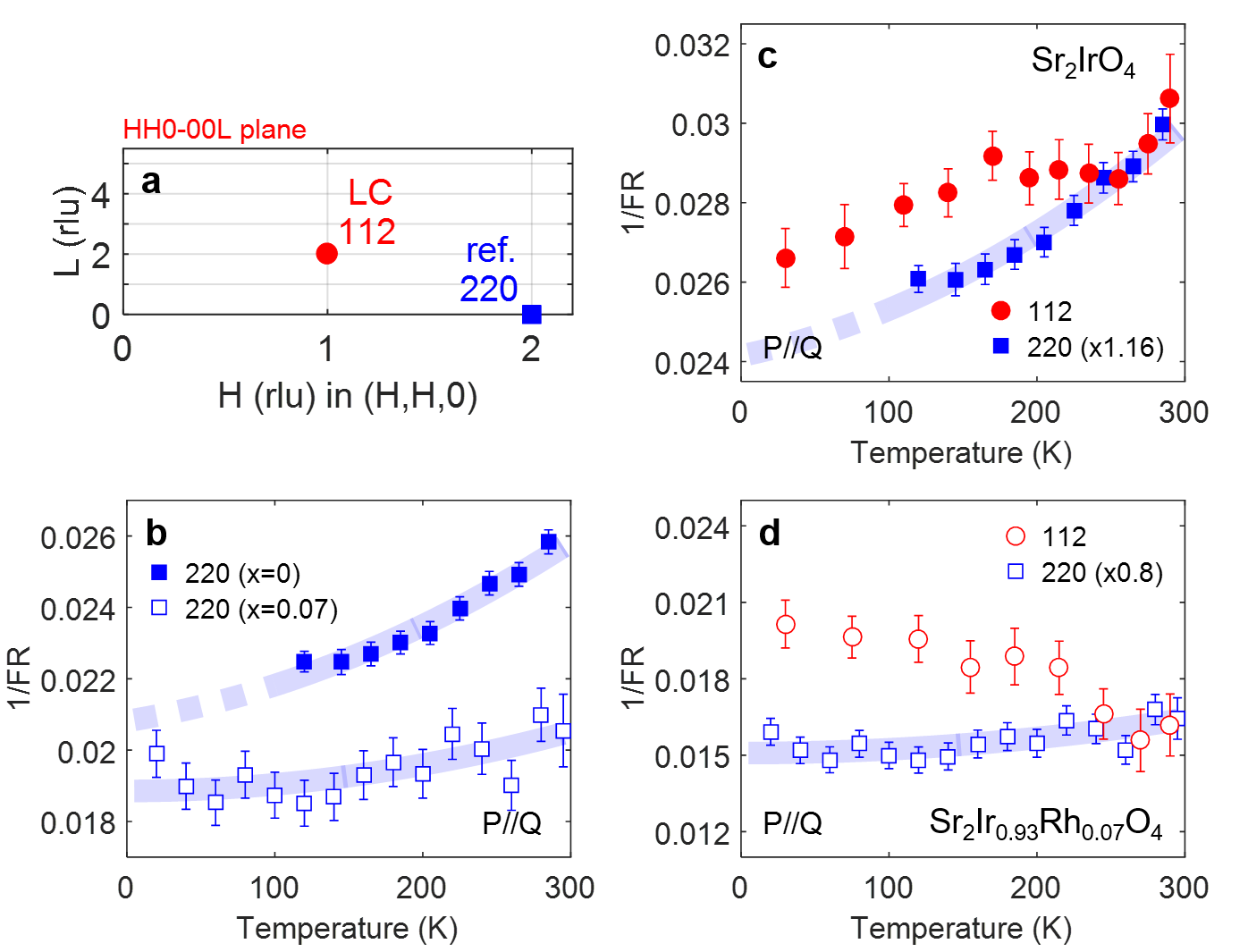
In order to reveal a small magnetic signal on top of the nuclear polarization leakage in the SF channel, one has to pick up the weakest nuclear Bragg peaks (with the appropriate symmetry for the LC phase) to get the better signal-to-background ratio. In addition, the magnetic form factor is generally suppressed at a high momentum transfer. Considering these constraints, the reflection has been studied, which has the lowest of the allowed nuclear Bragg peaks for the LC phase. Further, in order to determine the temperature dependence of the bare flipping ratio, , a non-magnetic reference Bragg peak is measured where the magnetic scattering is zero or small enough and where the spectrometer geometry is kept similar. Here, we chose the Bragg peak (see Fig. 6a) as the reference because a magnetic signal is expected to be considerably reduced by the magnetic form factor and the spectrometer geometry is not changed much with respect to . Using , obtained from the non-magnetic reference, one can then determine the intrinsic polarization leakage and next extract from the SF intensity the true magnetic one at , .
For the pure sample, the at the is 39 at 300 K and it increases up to 45 at 100 K, meaning that (reported in Fig. 6b) decreases upon cooling. That smooth decrease indicates no magnetic signal because one should observe a sudden increase of 1/FR in case of a magnetic order. The for the doped sample is higher (50) (1/FR reported in Fig. 6b) and much stable in temperature. That proves as well no magnetic signal at the peak in the doped sample. The observed temperature-dependent can therefore be taken as the bare for the polarization calibration.
In contrast, the at the shows a clear change of slope around 200–250 K as shown in Fig. 6c,d. The is 33–38 and 50–63 for the pure and doped sample, respectively. This main difference of the magnitude of FR originates from different experimental conditions such as sample mosaicity, the number of blades on the analyzer and optimization of the guide field. In order to estimate the bare for the , the is scaled by a factor that gives the same value with the at high temperature above 250 K. Then, as shown in Fig. 6c-d, we clearly observe a departure of from at low temperature. Using this , the bare polarization leakage, in the SF channel can be determined at . By subtracting it from the measured , the magnetic intensity can then be reported as, . We applied this method in the data analysis presented in Fig. 3 of the main manuscript.
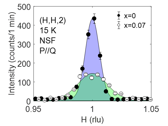
Note that, for a quantitative comparison of the magnetic intensities of both samples, all raw intensities have been background-subtracted, normalized to the same monitor counts and weighted by an estimated sample weight. The Fig. 7 depicts scans of the nuclear Bragg peak intensity at along in both samples. Due to a broader mosaicity of coaligned crystals, the peak width is broader in the doped sample. From Fig. 7, one deduces the integrated intensity of the Bragg peak, which is in the doped sample 1.6 times smaller than in the pure sample. Taking that into account, one could compare the magnetic intensity of the observed hidden order around 240 K for both the pure and doped samples. We found a similar amount of the magnetic intensity in both samples as shown in Fig. 3b-c of the manuscript.
Supplementary Note 5
Can an antiferromagnetic structure explain the hidden magnetic order at ?
The fact that we have ascribed the magnetic intensity at to a hidden magnetic order deserves additional comments. Briefly, the hidden order at cannot be described by any stacking of the planar pseudo-spin, , antiferromagnetic (AFM) pattern. Below, we discuss different AFM models considered in the literature:
First, in the AFM model (AF-I), the magnetic intensity is expected at some . However, it should be zero for =2 because it does not preserve the body-centered symmetry of the unit cell, so should be odd or . As a matter of fact, a tiny magnetic intensity (about a hundred times weaker than at ) has been reported at in pure [8]. That contribution is much weaker than at because the magnetic intensity at is proportional to the non-collinear pattern of the Ir moment. It is typically proportional to the square of the planar tilt angle of the IrO6 octahedra, with .
Second, in the AFM model (AF-II), a magnetic intensity at could exist in principle due to the ferromagnetic component. However, this interpretation can be excluded in both samples we have studied. First, in the pure sample, the ferromagnetic order is absent (see Fig.1 of the manuscript) [8, 9] and can be only induced by an applied magnetic field of about 2000 Oe [3]. Second, under Rh substitution, such a ferromagnetic order indeed develops but only below [10] as it results from the canting of the AFM order, clearly lower than . We therefore rule out the weak ferromagnetism derived from the canted AFM order as a candidate to account for the observed magnetic scattering at .
Third, in the hypothethic model considered by Di Matteo and Norman [11], a magnetic intensity will be also present at some positions. The structure factor for the stacking is not zero only for even as it keeps the body-centered symmetry of the unit-cell. Further, due to the glide plane, the structure factor is proportional to . Actually, it gives zero intensity at and then is not consistent with our finding. Further, such an AFM phase, , would also lead to magnetic contributions at for odd , which are not observed in any neutron diffraction reports [8, 9] in pure as well as shown in the Fig. 2d of the manuscript.
Finally, one should stress that magnetic contribution from any of these AFM phases at would be negligible as it is systematially proportional to with . Then, any effect around that -position would be quantitatively too weak to be measured in our experiment. In absence of a planar tilt, it would even be strictly zero, although the signal for the LC phase will be still not zero.
References
- [1] Fauqué, B. et al. Magnetic order in the pseudogap phase of high- superconductors. Physical Review Letters 96, 197001 (2006).
- [2] Bourges, P. & Sidis, Y. Novel magnetic order in the pseudogap state of high- copper oxides superconductors. Comptes Rendus Physique 12, 461–479 (2011).
- [3] Kim, B. et al. Phase-sensitive observation of a spin-orbital mott state in Sr2IrO4. Science 323, 1329–1332 (2009).
- [4] Qi, T. et al. Spin-orbit tuned metal-insulator transitions in single-crystal Sr2Ir1-xRhxO4 . Physical Review B 86, 125105 (2012).
- [5] Ye, F. et al. Structure symmetry determination and magnetic evolution in Sr2Ir1-xRhxO4. Physical Review B 92, 201112 (2015).
- [6] Mook, H., Sidis, Y., Fauqué, B., Balédent, V. & Bourges, P. Observation of magnetic order in a superconducting YBa2Cu3O6.6 single crystal using polarized neutron scattering. Physical Review B 78, 020506 (2008).
- [7] Li, Y. et al. Unusual magnetic order in the pseudogap region of the superconductor HgBa2CuO4+δ. Nature 455, 372–375 (2008).
- [8] Ye, F. et al. Magnetic and crystal structures of Sr2IrO4: A neutron diffraction study. Physical Review B 87, 140406 (2013).
- [9] Dhital, C. et al. Neutron scattering study of correlated phase behavior in Sr2IrO4. Physical Review B 87, 144405 (2013).
- [10] Clancy, J. et al. Dilute magnetism and spin-orbital percolation effects in Sr2Ir1-xRhxO4. Physical Review B 89, 054409 (2014).
- [11] Di Matteo, S. & Norman, M. R. Magnetic ground state of Sr2IrO4 and implications for second-harmonic generation. Phys. Rev. B 94, 075148 (2016).