Irradiation study of UV Silicon Photomultipliers for the Mu2e Calorimeter
Abstract
The Mu2e calorimeter is composed of 1400 un-doped CsI crystals, coupled to large area UV extended Silicon Photomultipliers (SiPMs), arranged in two annular disks. This calorimeter has to provide precise information on energy, timing and position resolutions. It should also be fast enough to handle the high rate background and it must operate and survive in the high radiation environment. Simulation studies estimated that, in the highest irradiated regions, each photo-sensor will absorb a dose of 20 krad and will be exposed to a neutron fluency of n1MeV/cm2 in three years of running, with a safety factor of 3 included.
At the end of 2015, we have concluded an irradiation campaign at the Frascati Neutron Generator (FNG, Frascati, Italy) measuring the response of two different 16 array models from Hamamatsu, which differ for the protection windows and a SiPM from FBK. In 2016, we have carried out two additional irradiation campaigns with neutrons and photons at the Helmholtz-Zentrum Dresden-Rossendorf (HZDR, Dresden, Germany) and at the Calliope gamma irradiation facility at ENEA-Casaccia, respectively.
A negligible increment of the leakage current and no gain change have been observed with the dose irradiation. On the other hand, at the end of the neutron irradiation, the gain does not show large changes whilst the leakage current increases by around a factor of 2000. In these conditions, the too high leakage current makes problematic to bias the SiPMs, thus requiring to cool them down to a running temperature of C.
1 The Mu2e experiment
The goal of the Mu2e experiment is to search for the neutrinoless, coherent conversion of muons into electrons in the field of a nucleus and improve by four orders of magnitude the previous sensitivity set at 90 C.L. by the SINDRUM II experiment [1]. This corresponds to a limit on the ratio between the conversion and nuclear muon capture rates of : , Mu2e hopes to achieve a Single Event Sensitivity (SES) of with event background. The Mu2e apparatus is extensively documented in its Technical Design Report [2]. As shown in Figure 1, the layout of the Superconducting Solenoid Magnet System has a typical S-shape. In order to limit backgrounds from muons that might stop on gas atoms and to reduce the contribution of multiple scattering for low momentum particles, the inner bore of the solenoids is evacuated to Torr.
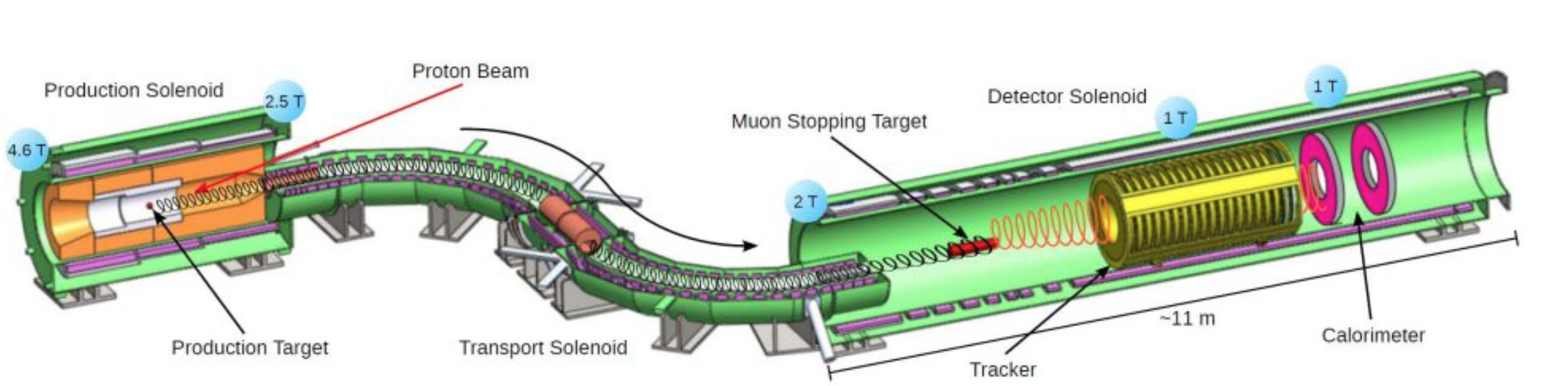
The solenoids are organized into three sub-systems: Production Solenoid (PS), Transport Solenoid (TS) and Detector Solenoid (DS). The 8 GeV proton beam (i.e. above the antiproton production threshold energy) coming from the Fermilab accelerator system enters the PS, hitting the production target. The reaction products, of selected charge sign, are transported through the S-shaped Transport Solenoid, which is long enough to allow the decay of almost all hadrons while suppressing line-of-sight particles. The resulting negative muon beam enters the Detector Solenoid and hits the aluminum target: of the muons are stopped at a frequency of GHz while the other proceed toward the muon beam stop. of the muons stopped are captured by the atoms and decay or convert into electrons while the rest are captured by the nucleus (). Momentum and energy of the electrons produced in the Decay in Orbit (DIO) and Conversion Electrons (CE) events are measured by the cylindrical-shaped tracker and by the two-disks calorimeter, respectively. Downstream of the proton beam pipe, outside the PS, an extinction monitor is used to measure the number of protons in between two subsequent proton pulses. The Detector Solenoid is surrounded by a cosmic ray veto system. Outside the DS, a stopping target monitor is used to measure the total number of muon captures.
1.1 The Mu2e calorimeter
The request of the Mu2e calorimeter are to provide: (i) shower shape, energy, and timing information that, in combination with information from the tracker, can distinguish electrons from muons and pions, (ii) a “seed” to improve tracker pattern recognition and reconstruction efficiency, (iii) the means to implement an independent trigger based on the sum and pattern of
energy deposition. Moreover, the Mu2e calorimeter must operate in a high-rate, high-radiation environment, in vacuum and in presence of a 1T magnetic field. This motivates a fast response, an excellent time resolution and good radiation hardness. After a long RD phase, the best compromise between costs and properties has been selected: the calorimeter design consists of 1346 un-doped CsI crystals located down-stream of the tracker, arranged in two disks, positioned at a distance of half wavelength of a typical conversion electron. For an overall description of the calorimeter, see [3].
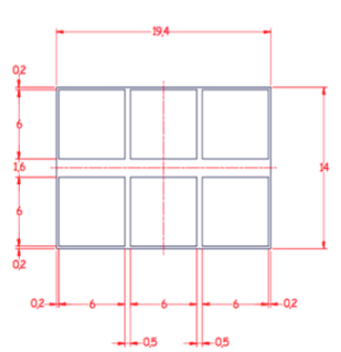
The crystals are parallelepipeds with squared faces of mm2 dimensions and are 200 mm long. Each crystal is read by two arrays of individual mm 2 UV-extended Silicon Photomultipliers (SiPMs), see Figure 2 left. The solid-state photodetectors are necessary due to the presence of the high magnetic field.
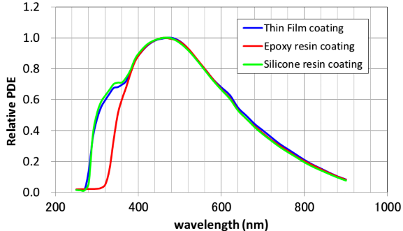
In order to match the wavelength of the emitted light produced by the CsI crystals (that is centered at 315 nm) the SiPMs have to be extended in the UV region, as shown in Figure 2 right. The serial connection has been chosen to overcome the issues related to the parallel connection which might affect the energy and time measurements, owing to the very large capacitance resulting in an increased noise, signal rise time and width. This is shown in Figure 3, where the signal width of a single SiPM and the series of three SiPMs are displayed.
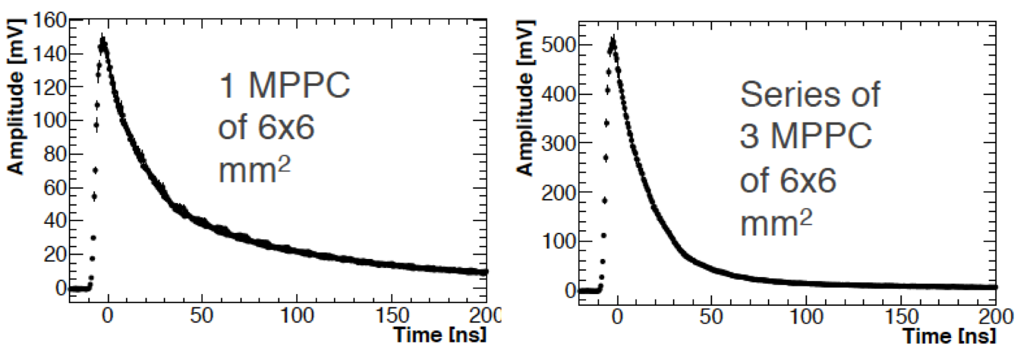
Differently from the parallel configuration, where the signal becomes wider, the pulse shape of a series of SiPMs results narrower than that of a single SiPM. This is due to the reduction of the total capacitance of the circuit. The shorter signal decay time minimizes the overall width of the Crystal+SiPM pulse height thus improving the pileup discrimination capability.
The Front End chips are connected directly to the sensors while the Slow Control and Digitization boards are mounted on crates located on top of each disk. The electronics must work adequately in vacuum and in presence of a high magnetic field and high radiation environment.
The equalization of the crystal response will be provided through a circulating radioactive source (FluorinertTM, C8F18), already experimented by BaBar [4] while a laser flasher system will be used for relative calibration and gain monitoring of the SiPMs. Usage of cosmic ray and DIO events for calibrating ”in-situ” along running is also planned.
2 The SiPM irradiation campaigns
The Mu2e calorimeter must operate and survive in a high radiation environment.
Simulation studies estimated that the Mu2e SiPMs have to withstand an equivalent neutron fluency, at 1 MeV energy, of n/cm2 and a Total Ionizing Dose (TID) of 20 krad of photons [5]. These values assumes three years of running and a factor of 2 safety as calculated in the hottest irradiated region, i.e. in the innermost ring of the first disk. For this reason, we have tested our sensors before and after irradiation to measure the variation of the leakage current and of their gain.
During the first irradiation campaigns in 2015, different models of UV-extended SiPMs have been tested: two from Hamamatsu [6], made of 16 mm2 cells, and one from FBK [7]. The two Hamamatsu SiPMs had equal layout but different protection material: one had a protection window with a silicon protection layer (SPL) while the other one had a Micro-Film (MF). The FBK SiPM was instead a 66 mm2 monolithic.
The general scheme of the experimental set-up used is shown in Figure 4.
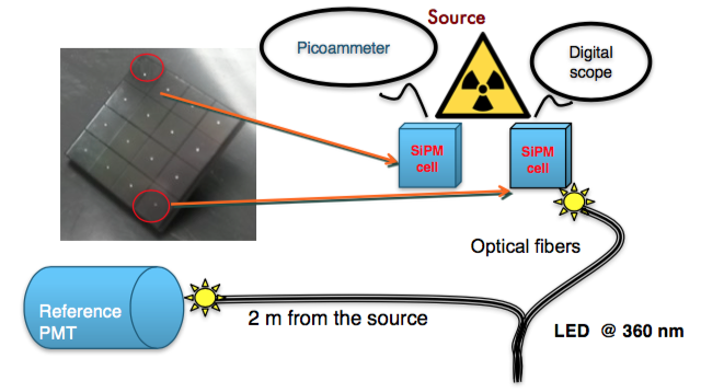
For the Hamamatsu SiPMs, we acquired the signal of two cells: one was used to read the leakage current, while the other one provided the response to a fixed UV led pulse, i.e. the gain. In order to precisely monitor the input led light, a UV photomultiplier has been illuminated with the same led pulse by means of a split fiber and placed in a safe region located 2 m far away from the source.
For the monolithic FBK SiPM, only the leakage current has been measured. Finally during 2016 a monolithic mm2 SiPM, UV extended by SPL type, has been tested at HZDR using a similar setup. In the latter case, both the leakage current and the response to a UV led have been collected.
2.1 Dose irradiation test
Irradiation tests with a ionization dose have been performed at the
ENEA CALLIOPE facility [8], where a 60Co source
produces ’s with an energy of 1.25 MeV. The activity of the source during our tests was
Bq, allowing to reach from 2 to 10 Gy/h at about
5 m distance.
The SPL SiPM was irradiated with these photons for three days absorbing a total dose of 20 krad.
The dose effect on SiPM performances is negligible both in term of leakage current and signal amplitude.
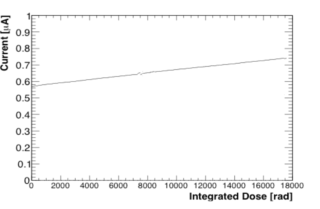
As shown in Fig. 5 the leakage current, which before the irradiation was of A, increased to A as soon as the irradiation started due to the Compton effect on the SiPM active surface. In three days of irradiation the current increased by A, thus practically doubling the initial dark current. The signal amplitude remained unchanged.
2.2 Neutron irradiation tests
The 2015 neutron irradiation tests have been performed at the ENEA
FNG facility [9], in Frascati, where a nearly isotropic 14 MeV neutron flux is produced
by stopping an accelerated deuteron beam on a Tritium target.
The maximum neutron intensity is n/s, close to
the target, with a 4 uniform production and a dependence on the distance,
, as . The desired neutron intensity is reached by either
positioning the SiPMs at the needed distance or by changing the deuteron
beam intensity. The temperature of the experimental hall was monitored and maintained between C and C.
The three different SiPM typologies, described before, were placed 7 cm far away from the source and exposed, in less than 4 hours, to a fluency of n/cm2, which corresponds to a neutron fluency equal to 2.2 times that expected in the experimental lifetime.The signal peak of the SPL SiPM decreased from 250 mV to 30 mV while the MF one decreased from mV to mV. The leakage current of the different SiPMs tested, as a function of the integrated flux, is reported in Fig. 6.
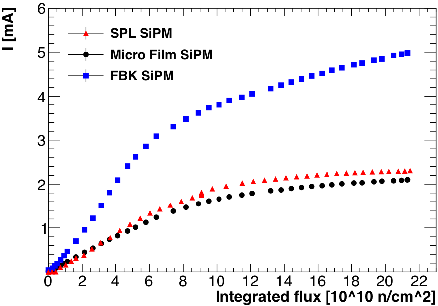
In order to compare results from SiPMs of different cell dimension, the FBK current has been reduced by a factor of 4 due to its larger active area.
A rising behavior of the dark current is clearly visible on all SiPMs: the leakage current of the MF SiPM increased from 16A to 2mA, the one of the SPL SiPM from 100 A to 2.2 mA and the FBK one from A to mA. The observed response to the led light decreased of more than a factor of 3. Even if the hall temperature was quite stable during irradiation, the observed gain drop was dominated by the SiPM temperature increment due to the Joule effect.
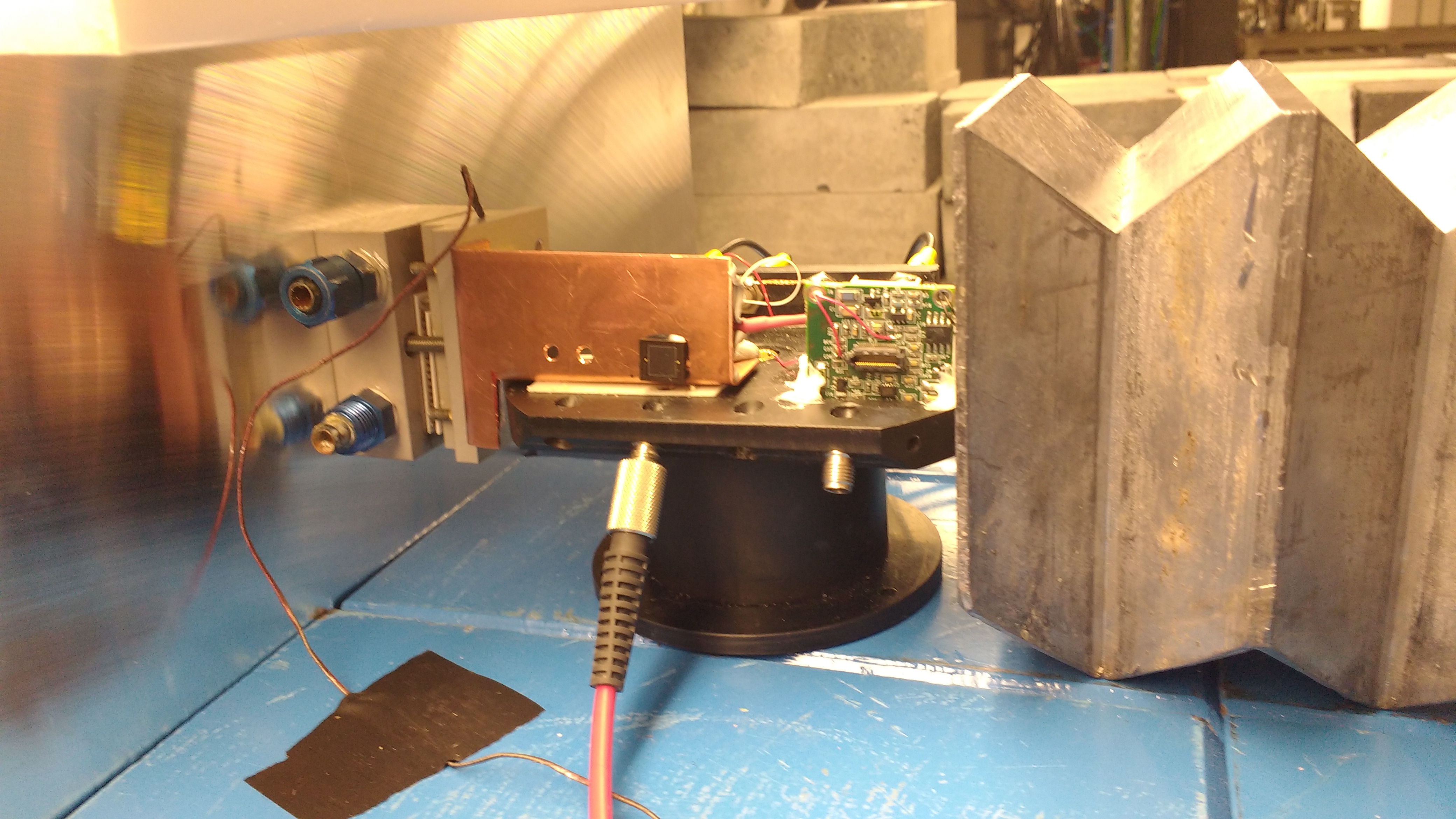
In order to confirm this, during 2016, an independent irradiation test has been performed at the EPOS source (HZDR, Dresden) with 1 MeV neutrons. The experimental setup used is reported in Figure 7: a SPL SiPM was located over the source in a place where no dose was present and with the active area positioned parallel to the incoming neutron flux. The SiPM was monitored both in current and in charge while illuminated with an UV led. To maintain the SiPM temperature as stable as possible, the irradiated SiPM was connected to a Peltier cell, with the hot side glued to a cooling system. The SiPM temperature was monitored using a PT1000. To control and monitor the Hamamatsu devices, the same experimental setup reported in Figure 4 was used. The SiPM was biased at V.
The total neutron fluence absorbed by the SiPM in five days was n1MeV/cm2, that is three times the flux expected in the hottest region in 3 years of running.
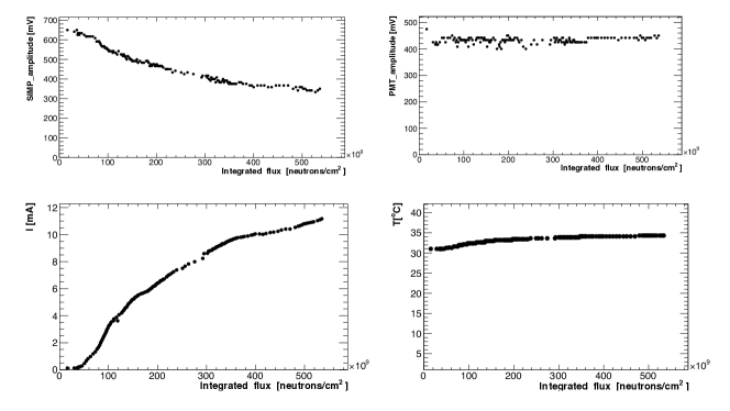
In Figure 8, the irradiation results are shown as a function of the integrated flux.
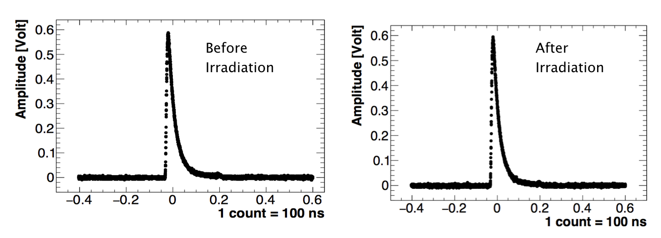
The signal peak decreased from 650 mV to 400 mV, due to the residual
temperature variation. A rising behaviour of the SiPM leakage current, from 60A up to 12 mA, is instead clearly visible.
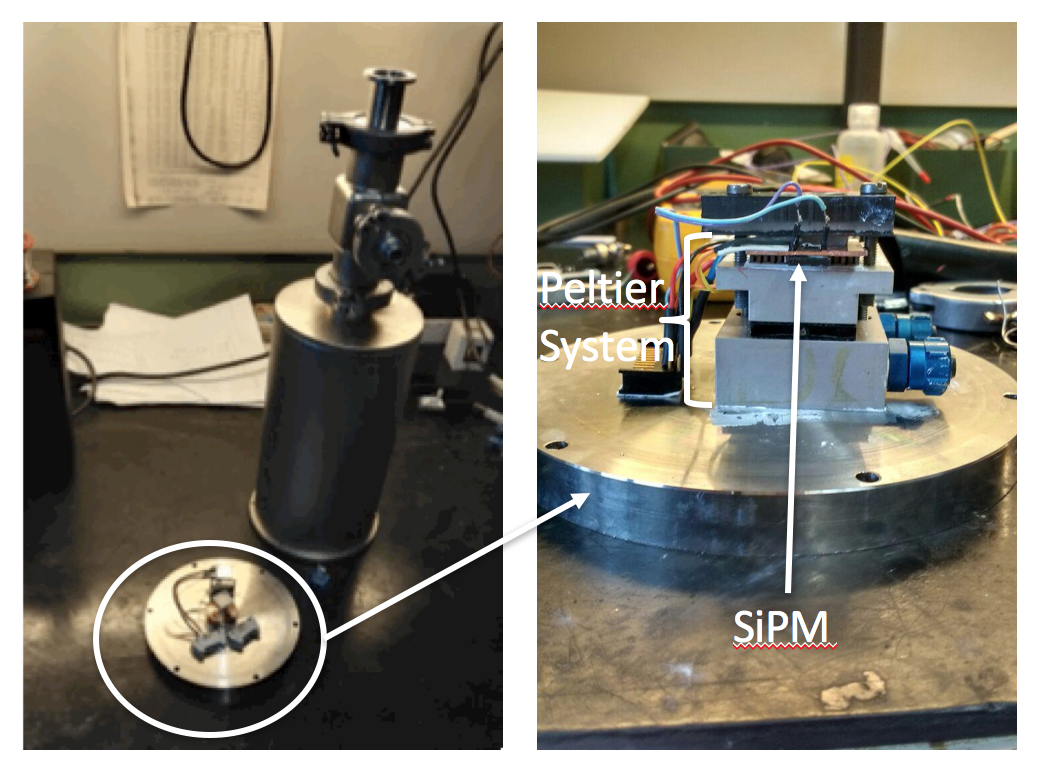
In order to study the SiPM properties as a function of its temperature, the SiPM irradiated at EPOS and one unirradiated SiPM have been tested in a vacuum chamber at mbar and cooled by means of a cascade of two Peltier cells. The SiPM temperature was monitored by a PT1000 sensor.
A UV- LED was illuminating directly the sample inside the chamber. The experimental set up used is shown in Figure 9.
The dark current was recorded and plotted as a function of the temperature using a pico-ammeter. In order to maintain the gain constant during the test, the SiPM was illuminated with a LED and the peak of the signal pulse height acquired with a digital scope. When varying the temperature, we adjusted the operation voltage by keeping constant the signal amplitude. Results are in Figure 10. The shape of the two distributions is similar but the dark current for the irradiated SiPM is larger by at least three orders of magnitude.
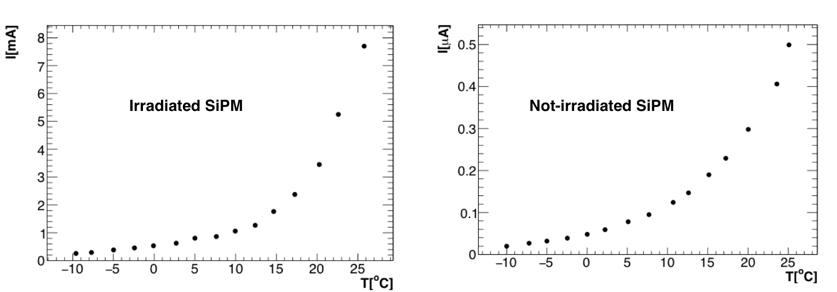
The bias supply of the front-end electronics requires the current of each channel to be mA so that it is necessary to run the SiPM at T C.
Since, as shown in Figure 10, at C the current of a single mm2 SiPM reaches mA, and a serial connection of three cm2 SiPMs will have the same current, we expect that in the parallel configuration of the two series a current I mA will flow, satisfying our requirements.
At the moment of writing, the Mu2e calorimeter group is designing the front end electronics and the sensor cooling system to keep the SiPM
at a running temperature between C and C.
3 Conclusions
The determination of the SiPM charge and leakage current variation during the irradiation tests provided an important benchmark for the Mu2e calorimeter where a high radiation environment is foreseen. While the total neutron flux causes a large increase of the leakage current, a dose up to 200 Gy causes a negligible effect. The response is slightly affected by the irradiation. Changes are still acceptable for the running condition in the experiment but this requires to cool down the SiPMs to a running temperature of C.
Acknowledgments
This work was supported by the EU Horizon 2020 Research and Innovation Programme under the Marie Sklodowska-Curie Grant Agreement No. 690835.
References
- [1] W. Bertl et al. A search for conversion in muonic gold. EPJ C, 47(2):337-346, 2006
- [2] L. Bartoszek et al., Mu2e Technical Design Report, arXiv:1501.05241
- [3] N. Atanov et al.,The Calorimeter of the Mu2e experiment at Fermilab, these proceedings.
- [4] B. Lewandowski. The BaBar electromagnetic calorimeter. Nucl. Instrum. Meth., A494(1-3):303 -307, 2002. Proc. 8th International Conference on Instrumentation for Colliding Beam Physics.
- [5] G. Pezzullo and B. Echenard, Study of the radiation dose and neutron flux on the calorimeter, Mu2e-doc-2853, 2013, unpublished.
-
[6]
http://www.hamamatsu.com/us/en/index.html -
[7]
https://srs.fbk.eu/optimization-sipm-technology - [8] S. Baccaro, A. Cecilia and A. Pasquali, irradiation facility at ENEA-Casaccia Centre, Roma, ENEA Report RT/2005/28/FIS (2005).
- [9] M. Martone. M. Angelone and M. Pillon, The 14 MeV Frascati neutron Generator, Journal of Nuclear Materials 212-215 (1994) 1662-1664.