Understanding stability diagram of perpendicular magnetic tunnel junctions
Abstract
Perpendicular magnetic tunnel junctions (MTJ) with a bottom pinned reference layer and a composite free layer (FL) are investigated. Different thicknesses of the FL were tested to obtain an optimal balance between tunneling magnetoresistance (TMR) ratio and perpendicular magnetic anisotropy. After annealing at 400 ∘C, the TMR ratio for 1.5 nm thick CoFeB sublayer reached 180 % at room temperature and 280 % at 20 K with an MgO tunnel barrier thickness corresponding to the resistance area product RA = 10 Ohmm2. The voltage vs. magnetic field stability diagrams measured in pillar-shaped MTJs with 130 nm diameter indicate the competition between spin transfer torque (STT), voltage controlled magnetic anisotropy (VCMA) and temperature effects in the switching process. An extended stability phase diagram model that takes into account all three effects and the effective damping measured independently using broadband ferromagnetic resonance technique enabled the determination of both STT and VCMA coefficients that are responsible for the FL magnetization switching.
I Introduction
Magnetic tunnel junctions (MTJs) have become a basic building block for various types of spintronics devices, such as magnetic random access memory (MRAM) cells, magnetic field sensors and microwave generators or detectors stamps_2014_2014 . The properties of spintronics devices, such as thermal stability of an MRAM cell ikeda_perpendicular-anisotropy_2010 , or sensitivity of microwave detectors fang_giant_2016 utilizin g MTJs can be greatly improved by using magnetic layers with perpendicular anisotropy yakata_influence_2009 . Among a few ways to realize such a perpendicular MTJ, taking advantage of the interface anisotropy component koziol-rachwal_room-temperature_2013 yields the best results so far, especially in terms of high tunneling magnetoresistance ratio (TMR), which is measured typically in MTJs with CoFeB/MgO/CoFeB trilayer. Recent studies on perpendicular MTJ showed the TMR ratio exceeding 200% tezuka_perpendicular_2016 thanks to careful optimization of both the free layer (FL) and reference layer (RL) structure yakushiji_perpendicular_2016 . In addition, one of the key challenges for the commercial development of spin transfer torque (STT)-MRAM is to optimize perpendicular MTJ to withstand the temperature budget introduced at the back end of line CMOS fabrication process with temperatures up to 400 ∘C. To achieve this a careful design of the layer stack, taking into account all constituent layers as well as the properties and the treatment of the bottom electrode, has to be performed.
In this letter, we report on the perpendicular MTJ with a composite CoFeB/W/CoFeB FL yakushiji_ultralow-voltage_2013 ; sato_properties_2014 , which is characterized by high perpendicular magnetic anisotropy and spin polarization resulting in up to 180 % TMR measured at room temperature and above 280 % TMR at low temperature. The RL is pinned to a synthetic ferromagnet (SyF) consisting of Co/Pt super-latices kugler_Co-Pt_2012 coupled by a thin Ru spacer. Electrical transport measurements were performed in MTJs patterned into 130-nm diameter pillar. Voltage vs. perpendicular magnetic field switching diagrams worledge_spin_2011 ; oh_bias-voltage_2009 are measured in order to separate between STT, voltage control of magnetic anisotropy (VCMA) and temperature effects. An analytic model based on work by Bernert et al. bernert_phase_2014 was extended to reproduce the experimental results.
II Experiment
The multilayers with the following structure were deposited: buffer / SyF / separator /CoFeB(1) / MgO(0.82) / CoFeB() / W(0.3) / CoFeB(0.5) / MgO (0.76) / capping (thicknesses in nm), with ranging from 1 up to 1.6 nm, using Singulus TIMARIS sputtering system. The bottom Co/Pt super-lattices coupled by a thin Ru spacer are characterized by high perpendicular magnetic anisotropy (PMA). The Ta/Co/W-based separator ensures high ferromagnetic coupling between the top super-lattice and the RL. In addition, it provides structural transition from a face center cubic SyF kanak_influence_2007 to a body center cubic CoFeB and contributes to the absorption of B atoms from CoFeB during annealing and crystallization processes.
After the deposition, the samples were annealed at 400 ∘C to induce proper crystallographic orientation of Fe-rich CoFeB and PMA of the CoFeB/MgO interfaces. Wafer-level parameters of the deposited multilayers were investigated by current in-plane tunneling (CIPT) worledge_magnetoresistance_2003 , vibrating sample magnetometry (VSM) and broadband ferromagnetic resonance (FMR) methods silva_inductive_1999 . The latter was performed by measuring the complex transmission coefficient (S21) in a dedicated coplanar waveguide with a 10 8 mm unpatterned sample placed face down. The frequency of the vector network analyzer is kept between 4 and 16 GHz, while sweeping the perpendicular magnetic field in 550 kA/m range.
After the above mentioned wafer-level measurements, selected MTJs were patterned into circular cross-section pillars with diameter ranging from 130 up to 980 nm by means of electron-beam lithography, ion-beam etching and lift-off process.
The transport properties presented in this work were measured for the smallest devices with the area of = 0.013 in a dedicated probe station equipped with magnetic field source. Four-probe method with a voltage source was used to apply 1-ms long pulses and measure the resistance during this voltage-pulse application. The stability diagrams were determined by sweeping the voltage pulses amplitude in the presence of a given magnetic field. Selected devices were characterized at low temperatures of = 20 K in order to determine the temperature influence on the magnetization switching properties.
III Modelling
Magnetization direction of the FL () was calculated based on the Landau-Lifschitz-Gilbert (LLG) equation with the following STT components taken into account:
| (1) |
where = , with the gyromagnetic ratio = ()/ = 28 GHz/T, is the permeability of the free space, is the Lande spectroscopic splitting factor, is the Bohr magneton, is the reduced Planck’s constant, and are the parallel and perpendicular STT coefficients expressed in T/V and T/V2 units, respectively, is the magnetization damping, and are the MTJ resistance in a given state and minimal (parallel state) resistance, is the effective magnetic field: = + , where, is the external perpendicular field, is the switching field and is the offset field.
Stability diagram was modeled based on Ref.bernert_phase_2014 :
| (2) |
where, is the switching voltage. It was assumed that parallel (perpendicular) torque component is a linear (quadratic) function of the applied current skowronski_influence_2013 . To account for the additional physical effects that contribute to the stability diagram, namely VCMA and temperature effects, is scaled by the factor:
| (3) |
where is the applied voltage, is the coercive field, is the VCMA coefficient shiota_quantitative_2011 ; skowronski_magnetic_2012 and is the ambient temperature. The dependence of the switching field on the temperature is represented by , which in the first approximation is a square-root function raquet_dynamical_1995 .
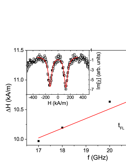
The damping factor was measured independently by the broadband FMR technique. For each microwave frequency , the complex magnetic susceptibility vs. magnetic field is extracted from S21 measurement by subtracting the magnetic independent offset and time-dependent drift nembach_perpendicular_2011 :
| (4) |
where = - is the effective magnetization, magnetization saturation and perpendicular magnetic anisotropy field, respectively, is the linewidth and = / . Figure 1 presents the dependence of the on the excitation frequency fitted by the Eq. 5:
| (5) |
IV Results and discussion
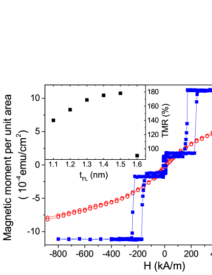
VSM measurements of a representative sample with = 1.1 nm presented in Fig. 2 reveals independent switching of the FL (at small magnetic fields below 50 kA/m) and RL (at high magnetic fields between 150 and 300 kA/m), which ensures bistable parallel (P) and antiparallel (AP) state. The FL magnetization was calculated and yielded = 1.12 T. An inset of Fig. 2 depicts the TMR ratio for different measured on the wafer-level using CIPT method. An increase of the TMR from 140% for = 1.1 nm up to TMR = 180% for = 1.5 nm is explained by an increase of the spin polarization for the thicker ferromagnetic layer. A rapid reduction of the TMR for = 1.6 nm is caused by the transition of the FL magnetization vector to the sample plane. After the patterning process the TMR ratio dropped by about 5-15%, which is explained by the appearance of the small serial parasitic resistance that has negligible influence on the MTJ parameters derived afterwards.
Figure 3 presents the TMR vs. magnetic field dependence measured in the MTJ with different . Increase in leads to an increase in TMR ratio and decrease in the coercive field. The offset field of about = 25 kA/m originates from the stray field, which depends on the MTJ lateral size.
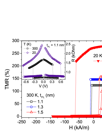
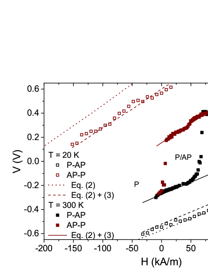
To further elucidate on the properties of the fabricated MTJ, current (voltage)-induced switching loops were measured in a presence of the perpendicular magnetic field. Inset of Fig. 3 presents a representative resistance vs. voltage loop measured in a magnetic field compensating the offset field in the MTJ with = 1.1 nm. It has been already established that apart from the conventional STT effect observed in MTJs with relatively thin MgO barriers, the switching process can be also affected by the VCMA effect in a thin FL zhu_voltage-induced_2012 ; shiota_induction_2011 . To investigate the switching process in more detail, we repeated the R(V) loop measurements, with different constant magnetic field. The stability diagram obtained in this way both at room temperature ( = 300 K) and low temperature ( = 20 K) for the MTJ with = 1.1 nm is presented in Fig. 4. To understand these diagrams, the following fitting procedure was used. First, low-temperature data were modeled using Eq. 2 to obtain , (being the offset field measured at low bias voltage) and STT coefficients, which are little affected by heat. The slope of V(H) depends mostly on , whereas, the vertical offset is adjusted by - solid lines in Fig. 4. Next, to compensate the offset between AP-P and P-AP switching voltages (which take place at opposite electric field applied to the MgO/CoFeB interface) was introduced according to the Eq. 3, without temperature influence so far ( = 0). Finally, thermal reduction of was introduced by adjusting to fit the stability diagram obtained at room temperature. In addition, for the precise derivation of the STT coefficients, the magnetization damping was calculated based on an independent FMR measurement presented above and included in Tab. 1.
Fitting the experimental stability diagram to the Eq. 2 and 3 yielded the temperature coefficients of = 0.0014 1/K. This parameter was kept constant for MTJs with different . Remaining parameters of the stability diagrams for each were modeled independently. For = 1.1 nm, the following STT components were obtained = 0.024 T/V and = 0.02 T/V2, however, we note that the modeled stability diagram is only little sensitive to , which agrees with another macrospin approach based on LLG equation presented in Ref. timopheev_respective_2015 . In-plane torque was thereafter recalculated using Eq. 6:
| (6) |
where is the FL volume and = -. As the result we obtained = 4.510-19 Nm/V, which agrees well with literature values of STT in case of an in-plane MTJ sankey_measurement_2007 ; kubota_quantitative_2007 ; skowronski_influence_2013 . Regarding the VCMA, the best results for MTJ with = 1.1 nm were obtained for = 0.12 1/V. Based on the following relation: = /, where = 0.82 nm is the tunnel barrier thickness, VCMA coefficient of = 46 fJ/Vm was calculated, which fits well the commonly measured values for CoFeB/MgO devices skowronski_underlayer_2015 ; alzate_temperature_2014 .VCMA and STT coefficients of all investigated MTJs are gathered in Tab. 1.
| (nm) | (kA/m) | (fJ/Vm) | (Nm) | no units | (kA/m) |
|---|---|---|---|---|---|
| 1.1 | 264 | 46 | 4.5 | 0.038 | -450 |
| 1.3 | 280 | 73 | 4.5 | 0.044 | -15 |
| 1.5 | 72 | 66 | 5.9 | 0.087 | -0.5 |
The in-plane torque component obtained from the stability diagram is almost constant as a function of , which is explained by little dependence of the TMR ratio, and thus the spin polarization on the ferromagnetic layer thickness in the investigated regime. The VCMA coefficient is comparable for MTJs with = 1.3 nm and 1.5 nm and greater than in MTJ with = 1.1 nm. This behavior is expected, as for thicker the absolute value of the effective magnetization is reduced and it is more susceptible to the anisotropy change induced by the electric field nozaki_large_2016 . Moreover, in the same thickness regime, where the transition between perpendicular and in-plane magnetization occurs, the effective damping increases, which may be attributed to an increase in the level of magnetization disorder frankowski_perpendicular_2017 .
V Summary
In summary, we investigated perpendicular MTJs with composite CoFeB/W/CoFeB FL of different thickness and SyF Co/Pt/Ru-pinned RL. In the investigated FL thickness range we observed an increase of the effective damping extracted from the broadband FMR measurements with increasing FL thickness, which is mainly caused by the reduction of the effective magnetization. After patterning MTJs into nano-meter scale pillars, we measured the resistance vs. voltage loops and created the stability diagrams for each FL thickness. To model the experimental data, we included the thermal and VCMA terms into the theoretical STT-switching phase diagram. Based on the fitting procedure, we obtained STT components together with the VCMA coefficient. Our findings shine more light on the switching process of MTJs applied in future MRAM technologies.
Acknowledgments
The authors would like to express their gratitude to Prof. T. Stobiecki for a fruitful discussion and his critical remarks. The project is supported by Polish National Center for Research and Development grant No. LIDER/467/L-6/14/NCBR/2015. Nanofabrication process was performed at Academic Center for Materials and Nanotechnology of AGH University. J.Ch. acknowledges the scholarship under Marian Smoluchowski Krakow Research Consortium KNOW programme. Numerical calculations were supported by PL-GRID infrastructure.
References
- [1] R. L Stamps, S. Breitkreutz, J. Akerman, A. V. Chumak, Y. Otani, G. E W Bauer, J.-U. Thiele, M. Bowen, S. A Majetich, M. Kläui, I. L. Prejbeanu, B. Dieny, N. M. Dempsey, and B. Hillebrands. The 2014 magnetism roadmap. Journal of Physics D: Applied Physics, 47:333001, 2014.
- [2] S. Ikeda, K. Miura, H. Yamamoto, K. Mizunuma, H. D. Gan, M. Endo, S. Kanai, J. Hayakawa, F. Matsukura, and H. Ohno. A perpendicular-anisotropy CoFeB-MgO magnetic tunnel junction. Nature Materials, 9:721, 2010.
- [3] B. Fang, M. Carpentieri, X. Hao, H. Jiang, J. A. Katine, I. N. Krivorotov, B. Ocker, J. Langer, K. L. Wang, B. Zhang, B. Azzerboni, P. Khalili Amiri, G. Finocchio, and Z. Zeng. Giant spin-torque diode sensitivity in the absence of bias magnetic field. Nature Communications, 7:11259, 2016.
- [4] S. Yakata, H. Kubota, Y. Suzuki, K. Yakushiji, A. Fukushima, S. Yuasa, and K. Ando. Influence of perpendicular magnetic anisotropy on spin-transfer switching current in CoFeB/MgO/CoFeB magnetic tunnel junctions. Journal of Applied Physics, 105:07D131, 2009.
- [5] A. Kozioł-Rachwał, W. Skowroński, T. Ślezak, D. Wilgocka-Ślezak, J. Przewoźnik, T. Stobiecki, Q. H. Qin, S. van Dijken, and J. Korecki. Room-temperature perpendicular magnetic anisotropy of MgO/Fe/MgO ultrathin films. Journal of Applied Physics, 114:224307, 2013.
- [6] N. Tezuka, S. Oikawa, I. Abe, M. Matsuura, S. Sugimoto, K. Nishimura, and T. Seino. Perpendicular Magnetic Tunnel Junctions With Low Resistance-Area Product: High Output Voltage and Bias Dependence of Magnetoresistance. IEEE Magnetics Letters, 7:1, 2016.
- [7] Kay Yakushiji, Hitoshi Kubota, Akio Fukushima, and Shinji Yuasa. Perpendicular magnetic tunnel junction with enhanced anisotropy obtained by utilizing an Ir/Co interface. Applied Physics Express, 9:013003, 2016.
- [8] Kay Yakushiji, Akio Fukushima, Hitoshi Kubota, Makoto Konoto, and Shinji Yuasa. Ultralow-voltage spin-transfer switching in perpendicularly magnetized magnetic tunnel junctions with synthetic antiferromagnetic reference layer. Applied Physics Express, 6:113006, 2013.
- [9] H. Sato, E. C. I. Enobio, M. Yamanouchi, S. Ikeda, S. Fukami, S. Kanai, F. Matsukura, and H. Ohno. Properties of magnetic tunnel junctions with a MgO/CoFeB/Ta/CoFeB/MgO recording structure down to junction diameter of 11 nm. Applied Physics Letters, 105:062403, 2014.
- [10] Z. Kugler, J.-P. Grote, V. Drewello, O.Schebaum, G. Reiss, and A. Thomas. Co/Pt multilayer-based magnetic tunnel junctions with perpendicular magnetic anisotropy. Journal of Applied Physics, 111:07C703, 2012.
- [11] D. C. Worledge, G. Hu, David W. Abraham, J. Z. Sun, P. L. Trouilloud, J. Nowak, S. Brown, M. C. Gaidis, E. J. O’Sullivan, and R. P. Robertazzi. Spin torque switching of perpendicular Ta/CoFeB/MgO-based magnetic tunnel junctions. Applied Physics Letters, 98:022501, 2011.
- [12] Se-Chung Oh, Seung-Young Park, Aurélien Manchon, Mairbek Chshiev, Jae-Ho Han, Hyun-Woo Lee, Jang-Eun Lee, Kyung-Tae Nam, Younghun Jo, Yo-Chan Kong, Bernard Dieny, and Kyung-Jin Lee. Bias-voltage dependence of perpendicular spin-transfer torque in asymmetric MgO-based magnetic tunnel junctions. Nature Physics, 5:898, 2009.
- [13] K. Bernert, V. Sluka, C. Fowley, J. Lindner, J. Fassbender, and A. M. Deac. Phase diagrams of MgO magnetic tunnel junctions including the perpendicular spin-transfer torque in different geometries. Physical Review B, 89:134415, 2014.
- [14] J. Kanak, M. Czapkiewicz, T. Stobiecki, M. Kachel, I. Sveklo, A. Maziewski, and S. van Dijken. Influence of buffer layers on the texture and magnetic properties of co/pt multilayers with perpendicular anisotropy. Physica Status Solidi (a), 204:3950, 2007.
- [15] D. C. Worledge and P. L. Trouilloud. Magnetoresistance measurement of unpatterned magnetic tunnel junction wafers by current-in-plane tunneling. Applied Physics Letters, 83:84, 2003.
- [16] T. J. Silva, C. S. Lee, T. M. Crawford, and C. T. Rogers. Inductive measurement of ultrafast magnetization dynamics in thin-film permalloy. Journal of Applied Physics, 85:7849, 1999.
- [17] W. Skowroński, M. Czapkiewicz, M. Frankowski, J. Wrona, T. Stobiecki, G. Reiss, K. Chalapat, G. S. Paraoanu, and S. van Dijken. Influence of MgO tunnel barrier thickness on spin-transfer ferromagnetic resonance and torque in magnetic tunnel junctions. Physical Review B, 87:094419, 2013.
- [18] Yoichi Shiota, Shinichi Murakami, Frédéric Bonell, Takayuki Nozaki, Teruya Shinjo, and Yoshishige Suzuki. Quantitative evaluation of voltage-induced magnetic anisotropy change by magnetoresistance measurement. Applied Physics Express, 4:043005, 2011.
- [19] W. Skowroński, and P. Wiśniowski, T. Stobiecki, S. Cardoso, P. P. Freitas, and S. van Dijken. Magnetic field sensor with voltage-tunable sensing properties. Applied Physics Letters, 101:192401, 2012.
- [20] B. Raquet, M.D. Ortega, M. Goiran, A.R. Fert, J.P. Redoules, R. Mamy, J.C. Ousset, A. Sdaq, and A. Khmou. Dynamical properties of magnetization reversal in an ultrathin AuCo film. Journal of Magnetism and Magnetic Materials, 150:L5, 1995.
- [21] H. T. Nembach, T. J. Silva, J. M. Shaw, M. L. Schneider, M. J. Carey, S. Maat, and J. R. Childress. Perpendicular ferromagnetic resonance measurements of damping and lande g-factor in sputtered (Co2Mn)1-x Gex thin films. Physical Review B, 84:054424, 2011.
- [22] Jian Zhu, J. A. Katine, Graham E. Rowlands, Yu-Jin Chen, Zheng Duan, Juan G. Alzate, Pramey Upadhyaya, Juergen Langer, Pedram Khalili Amiri, and Kang L. Wang. Voltage-induced ferromagnetic resonance in magnetic tunnel junctions. Physical Review Letters, 108:197203, 2012.
- [23] Yoichi Shiota, Takayuki Nozaki, Frédéric Bonell, Shinichi Murakami, Teruya Shinjo, and Yoshishige Suzuki. Induction of coherent magnetization switching in a few atomic layers of FeCo using voltage pulses. Nature Materials, 11:39, 2012.
- [24] A. A. Timopheev, R. Sousa, M. Chshiev, L. D. Buda-Prejbeanu, and B. Dieny. Respective influence of in-plane and out-of-plane spin-transfer torques in magnetization switching of perpendicular magnetic tunnel junctions. Physical Review B, 92:104430, 2015.
- [25] Jack C. Sankey, Yong-Tao Cui, Jonathan Z. Sun, John C. Slonczewski, Robert A. Buhrman, and Daniel C. Ralph. Measurement of the spin-transfer-torque vector in magnetic tunnel junctions. Nature Physics, 4:67, 2007.
- [26] Hitoshi Kubota, Akio Fukushima, Kay Yakushiji, Taro Nagahama, Shinji Yuasa, Koji Ando, Hiroki Maehara, Yoshinori Nagamine, Koji Tsunekawa, David D. Djayaprawira, Naoki Watanabe, and Yoshishige Suzuki. Quantitative measurement of voltage dependence of spin-transfer torque in MgO-based magnetic tunnel junctions. Nature Physics, 4:37, 2007.
- [27] W. Skowroński, T. Nozaki, D. D. Lam, Y. Shiota, K. Yakushiji, H. Kubota, A. Fukushima, S. Yuasa, and Y. Suzuki. Underlayer material influence on electric-field controlled perpendicular magnetic anisotropy in CoFeB/MgO magnetic tunnel junctions. Physical Review B, 91:184410, 2015.
- [28] Juan G. Alzate, Pedram Khalili Amiri, Guoqiang Yu, Pramey Upadhyaya, Jordan A. Katine, Juergen Langer, Berthold Ocker, Ilya N. Krivorotov, and Kang L. Wang. Temperature dependence of the voltage-controlled perpendicular anisotropy in nanoscale MgO|CoFeB|Ta magnetic tunnel junctions. Applied Physics Letters, 104:112410, 2014.
- [29] Takayuki Nozaki, Anna Kozioł-Rachwał, Witold Skowroński, Vadym Zayets, Yoichi Shiota, Shingo Tamaru, Hitoshi Kubota, Akio Fukushima, Shinji Yuasa, and Yoshishige Suzuki. Large voltage-induced changes in the perpendicular magnetic anisotropy of an MgO-based tunnel junction with an ultrathin Fe layer. Physical Review Applied, 5:044006, 2016.
- [30] M. Frankowski, J. Chęciński, W. Skowroński, and T. Stobiecki. Perpendicular magnetic anisotropy influence on voltage-driven spin-diode effect in magnetic tunnel junctions: A micromagnetic study. Journal of Magnetism and Magnetic Materials, 429:11, 2017.