Topology optimization of multi-track ring resonators and 2D microcavities for nonlinear frequency conversion
Abstract
We exploit recently developed topology-optimization techniques to design complex, wavelength-scale resonators for enhancing various nonlinear and frequency conversion processes. In particular, we demonstrate aperiodic, multi-track ring resonators and 2D slab microcavities exhibiting long lifetimes , small modal volumes , and among the largest nonlinear overlaps (a generalization of phase matching in large-etalon waveguides) possible, paving the way for efficient, compact, and wide-bandwdith integrated nonlinear devices.
pacs:
190.0190, 050.1755Nonlinear frequency conversion (NFC) plays a crucial role in many photonic applications, including ultra-short pulse shaping DeLong et al. (1994); Arbore et al. (1997), spectroscopy Heinz et al. (1982), generating novel states of light Kuo et al. (2006); Vodopyanov et al. (2006); Krischek et al. (2010), and quantum information processing Vaziri et al. (2002); Tanzilli et al. (2005); Zaske et al. (2012). A well-known approach for lowering the power requirements of such nonlinear devices is that of employing optical resonators which confine light for long times (dimensionless lifetimes ) in small volumes Joannopoulos et al. (2008); Soljačić et al. (2002); Soljacic et al. (2003); Yanik et al. (2003, 2004); Bravo-Abad et al. (2010); Rivoire et al. (2009); Pernice et al. (2012); Bi et al. (2012); Buckley et al. (2014); Wang et al. (2014); Guo et al. (2016). Although microcavity resonators designed for on-chip, infrared applications promise some of the smallest confinement factors available, their implementation is highly limited by the difficult task of identifying wavelength-scale () structures supporting long-lived, resonant modes at widely separated wavelengths and satisfying rigid frequency-matching and mode-overlap constraints Rodriguez et al. (2007); Bravo-Abad et al. (2010). Recently, we proposed a computational framework based on large-scale topology-optimization (TO) techniques that enables automatic discovery of multilayer and grating structures exhibiting some of the largest SHG figures of merit ever predicted Lin et al. (2016).
In this letter, we extend our TO formulation to allow the possibility of more sophisticated nonlinear processes and apply it to the problem of designing rotationally symmetric and slab microresonators that exhibit high-efficiency second harmonic generation (SHG) and sum/difference frequency generation (SFG/DFG). In particular, we demonstrate multi-track ring resonators and proof-of-principle two-dimensional slab cavities supporting multiple, resonant modes (even several octaves apart) that would be impossible to design “by hand”. Our designs ensure frequency matching, long radiative lifetimes, and small (wavelength-scale) modal confinement while also simultaneously maximizing the nonlinear modal overlap (or “phase matching”) necessary for efficient NFC. For instance, we discover topology-optimized concentric ring cavities exhibiting SHG efficiencies as high as even with low operational , a performance that is on a par with recently fabricated -diameter, ultrahigh AlN microring resonators Guo et al. (2016) (); essentially, our topology-optimized cavities not only possess the smallest possible modal volumes , but can also operate over wider bandwidths by virtue of their increased nonlinear modal overlap.
As reviewed in Refs. Jensen and Sigmund, 2011; Liang and Johnson, 2013; Lin et al., 2016, a typical topology optimization problem seeks to maximize or minimize an objective function , subject to certain constraints , over a set of free variables or degrees of freedom (DOF):
| (1) | ||||
| (2) | ||||
| (3) |
where the DOFs are the normalized dielectric constants assigned to each pixel or voxel (indexed ) in a specified volume. The subscript denotes appropriate spatial discretization with respect to Cartesian or curvilinear coordinates. Depending on the choice of background (bg) and structural materials, is mapped onto position-dependent dielectric constant via . The binarity of the optimized structure is enforced by penalizing the intermediate values or utilizing a variety of filter and regularization methods Jensen and Sigmund (2011). Starting from a random initial guess or completely uniform space, the technique discovers complex structures automatically with the aid of powerful gradient-based algorithms such as the method of moving asymptotes (MMA) Svanberg (2002). For an electromagnetic problem, and are typically functions of the electric or magnetic fields integrated over some region, which are in turn solutions of Maxwell’s equations under some incident current or field. In what follows, we exploit direct solution of Maxwell’s equations,
| (4) |
describing the steady-state in response to incident currents at frequency . While solution of (4) is straightforward and commonplace, the key to making optimization problems tractable is to obtain a fast-converging and computationally efficient adjoint formulation of the problem Jensen and Sigmund (2011). Within the scope of TO, this requires efficient calculations of the derivatives at every pixel , which we perform by exploiting the adjoint-variable method (AVM) Jensen and Sigmund (2011).
Any NFC process can be viewed as a frequency mixing scheme in which two or more constituent photons at a set of frequencies interact to produce an output photon at frequency , where can be either negative or positive, depending on whether the corresponding photons are created or destroyed in the process Boyd (1992). Given an appropriate nonlinear tensor component , with , mediating an interaction between the polarization components and , , we begin with a collection of point dipole currents, each at the constituent frequency and positioned at the center of the computational cell , such that , where is a polarization vector chosen so as to excite the desired electric-field polarization components () of the corresponding mode. Given the choice of incident currents , we solve Maxwell’s equations to obtain the corresponding constituent electric-field response , from which one can construct a nonlinear polarization current , where and can be generally polarized () in a (chosen) direction that differs from the constituent polarizations . Here, (*) denotes complex conjugation for negative and no conjugation otherwise. Finally, maximizing the radiated power, , due to , one is immediately led to the following nonlinear topology optimization (NLTO) problem:
| (5) | ||||
Writing down the objective function in terms of the nonlinear polarization currents, it follows that solution of (5), obtained by employing any mathematical programming technique that makes use of gradient information, e.g. the adjoint variable method Jensen and Sigmund (2011), maximizes the nonlinear coefficient (mode overlap) associated with the aforementioned nonlinear optical process.
| Polarization | Thickness | ||||
|---|---|---|---|---|---|
| (0, 0) | 0.041 | 0.39 | |||
| (4, 8) | 0.009 | 0.30 | |||
| (5, 10) | 0.008 | 0.18 | |||
| (6, 12) | 0.008 | 0.18 | |||
| (10, 20) | 0.004 | 0.22 | |||
| (10, 21) | 0.004 | 0.24 |
| Polarization | Thickness | ||||
|---|---|---|---|---|---|
| 0.38 |
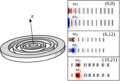
Multi-track ring resonators.— We first apply our NLTO formulation to the design of rotationally symmetric cavities for SHG. We consider a material platform consisting of gallium arsenide (GaAs) thin films cladded in silica. The result of the optimizations are described in Fig. 1 and Table 1, the latter of which summarizes the most important parameters, classified according to the choice of and , which denote the azimuthal mode numbers of fundamental and second harmonic modes, respectively. (Note that depending on the polarization of the two modes, different phase-matching conditions must be imposed Rodriguez et al. (2007); Bi et al. (2012); Wang et al. (2014), e.g. , so in our optimizations we consider different possible combinations.) The parameter is the nonlinear coupling strength between the interacting modes, which in the case of SHG is given by Lin et al. (2016):
| (6) |
In Table. 2, we also consider resonators optimized to enhance a SFG process involving three resonant modes, , with and . Note that two of these modes are more than an octave apart. The definition of the corresponding nonlinear overlap factor, i.e. the generalization of (7), can be found in Refs. Rodriguez et al., 2007; Burgess et al., 2009.
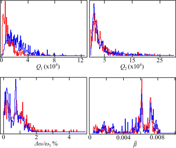
The resulting structures and figures of merit suggest the possibility of orders of magnitude improvements. In particular, we find that the largest overlap factors are achieved in the case , corresponding to highly confined modes with peak amplitudes near the center of the rings [Fig. 1(a)], in which case a relatively thicker cavity is required to mitigate out-of-plane radiation losses. From the optimized ’s and and assuming , we predict a SHG efficiency of . As expected, both radiative losses and decrease with increasing , as the modes become increasingly delocalized and move away from the center, resulting in larger mode volumes (Fig. 1b,c). Compared to the state-of-the-art microring resonator demonstrated in Guo et al. (2016), whose , our structures exhibit consistently larger overlaps, albeit with decreased radiative lifetimes. The main challenge in realizing multi-track designs is that, like photonic crystals and related structures that rely on careful interference effects, their s tend to be more sensitive to perturbations. In the case of centrally confined modes with , we observe the appearance of deeply subwavelength features near the cavity center where the fields are mostly confined. We find that these features are crucial to the integrity of the modes since they are responsible for the delicate interference process which cancels outgoing radiation, and therefore their absence greatly reduces the quality factors of the modes. Overall, for , we find that for operation with , a fabrication precision of several nanometers would be necessary to ensure quality factors on the order of . On the other hand, the optimized designs become increasingly robust for larger since they have fewer subwavelength features and smaller aspect ratios. Figure 2 shows distributions of the most important figures of merit for an ensemble of cavities subject to random, uniformly-distributed structural (position and thicknesses) perturbations in the range . We find that while the frequency mismatch and overlap factors are quite robust against variations, the quality factors can decrease to .
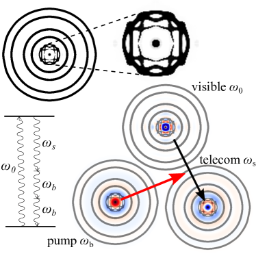
Slab microcavities.— We now consider a different class of structure and NFC process, namely DFG in slab microcavities. In particular, we consider a nonlinear process satisfying the frequency relation , with , , and denoting the frequencies of signal, emitted, and pump photons (see Fig. 3). Such a DFG process has important implications for single-photon frequency conversion, e.g. in nitrogen-vacancy (NV) color centers, where a single NV photon is converted to a telecommunication wavelength by pump light at , requiring resonances that are more than two octave away from one another Lin et al. (2015). In other words, the challenge is to design a diamond cavity that exhibits three widely separated strongly confined modes with large nonlinear interactions and lifetimes. Figure 3 presents a proof-of-concept 2D design that satisfies all of these requirements. Extension to 3D slabs of finite thickness (assuming similar lateral profiles and vertical confinement wavelength), one is led to the possibility of ultra-large , with
| (7) |
Note that the lifetimes of these 2D modes are bounded only by the finite size of our computational cell (and hence are ignored in our discussion), whereas in realistic 3D microcavities, they will be limited by vertical radiation losses Joannopoulos et al. (2008). Despite the two-dimensional aspect of this slab design, and in contrast to the fully 3D multi-track ring resonators above, these results provide proof of the existence of wavelength-scale photonic structures that can greatly enhance challenging NFC processes. One example is the NV problem described above, which is particularly challenging if a monolithic all-diamond approach is desired, in which case both single-photon emission and wavelength conversion are to be seamlessly realized in the same diamond cavity Lin et al. (2015). A viable solution that was recently proposed is the use of four-wave mixing Bragg scattering (FWM-BS) by way of whispering gallery modes Lin et al. (2015); Li et al. (2016), which are relatively easy to phase-match but suffer from large mode volumes. Furthermore, FWM-BS requires two pump lasers, at least one of which has a shorter wavelength than the converted signal photon, which could lead to spontaneous down-conversion and undesirable noise, degrading quantum fidelity, in contrast to the DFG scheme above, based on a long-wavelength pump Lin et al. (2015).
References
- DeLong et al. (1994) K. W. DeLong, R. Trebino, J. Hunter, and W. E. White, J. Opt. Soc. Am. B 11, 2206 (1994).
- Arbore et al. (1997) M. A. Arbore, A. Galvanauskas, D. Harter, M. H. Chou, and M. M. Fejer, Opt. Lett. 22, 1341 (1997).
- Heinz et al. (1982) T. F. Heinz, C. K. Chen, D. Ricard, and Y. R. Shen, Phys. Rev. Lett. 48, 478 (1982).
- Kuo et al. (2006) P. S. Kuo, K. L. Vodopyanov, M. M. Fejer, D. M. Simanovskii, X. Yu, J. S. Harris, D. Bliss, and D.Weyburne, Opt. Lett. 31, 71 (2006).
- Vodopyanov et al. (2006) K. L. Vodopyanov, M. M. Fejer, X. Yu, J. S. Harris, Y.-S. Lee, W. C. Hurlbut, V. G. Kozlov, D. Bliss, and C. Lynch, Appl. Phys. Lett. 89, 141119 (2006).
- Krischek et al. (2010) R. Krischek, W. Wieczorek, A. Ozawa, N. Kiesel, P. Michelberger, T. Udem, and H. Weinfurter, Nature Photonics 4, 170 (2010).
- Vaziri et al. (2002) A. Vaziri, G. Weihs, and A. Zeilinger, Phys. Rev. Lett. 89, 240401 (2002).
- Tanzilli et al. (2005) S. Tanzilli, W. Tittel, M. Halder, O. Alibart, P. Baldi, N. Gisin, and H. Zbinden, Nature 437, 116 (2005).
- Zaske et al. (2012) S. Zaske, A. Lenhard, C. A. Keßler, J. Kettler, C. Hepp, C. Arend, R. Albrecht, W.-M. Schulz, M. Jetter, P. Michler, and C. Becher, Phys. Rev. Lett. 109, 147404 (2012).
- Joannopoulos et al. (2008) J. D. Joannopoulos, S. G. Johnson, J. N. Winn, and R. D. Meade, Photonic Crystals: Molding the Flow of Light, 2nd ed. (Princeton University Press, 2008).
- Soljačić et al. (2002) M. Soljačić, M. Ibanescu, S. G. Johnson, Y. Fink, and J. D. Joannopoulos, Phys. Rev. E Rapid Commun. 66, 055601(R) (2002).
- Soljacic et al. (2003) M. Soljacic, C. Luo, J. D. Joannopoulos, and S. Fan, Opt. Lett. 28, 637 (2003).
- Yanik et al. (2003) M. F. Yanik, S. Fan, and M. Soljacic, Appl. Phys. Lett. 83, 2739 (2003).
- Yanik et al. (2004) M. F. Yanik, S. Fan, M. Soljačić, , J. D. Joannopoulos, and Yanik, Opt. Lett. 68, 2506 (2004).
- Bravo-Abad et al. (2010) J. Bravo-Abad, A. W. Rodriguez, J. D. Joannopoulos, P. T. Rakich, S. G. Johnson, and M. Soljacic, Appl. Phys. Lett. 96, 101110 (2010).
- Rivoire et al. (2009) K. Rivoire, Z. Lin, F. Hatami, W. T. Masselink, and J. Vučković, Opt. Express 17, 22609 (2009).
- Pernice et al. (2012) W. H. P. Pernice, C. Xiong, C. Schuck, and H. X. Tang, Applied Physics Letters 100, 223501 (2012), http://dx.doi.org/10.1063/1.4722941.
- Bi et al. (2012) Z.-F. Bi, A. W. Rodriguez, H. Hashemi, D. Duchesne, M. Loncar, K.-M. Wang, and S. G. Johnson, Opt. Express 20, 7526 (2012).
- Buckley et al. (2014) S. Buckley, M. Radulaski, J. L. Zhang, J. Petykiewicz, K. Biermann, and J. Vučković, Opt. Express 22, 26498 (2014).
- Wang et al. (2014) C. Wang, M. J. Burek, Z. Lin, H. A. Atikian, V. Venkataraman, I.-C. Huang, P. Stark, and M. Lončar, Optics express 22, 30924 (2014).
- Guo et al. (2016) X. Guo, C.-L. Zou, and H. X. Tang, Optica 3, 1126 (2016).
- Rodriguez et al. (2007) A. Rodriguez, M. Soljačić, J. D. Joannopulos, and S. G. Johnson, Opt. Express 15, 7303 (2007).
- Lin et al. (2016) Z. Lin, X. Liang, M. Lončar, S. G. Johnson, and A. W. Rodriguez, Optica 3, 233 (2016).
- Jensen and Sigmund (2011) J. Jensen and O. Sigmund, Laser and Photonics Reviews 5, 308 (2011).
- Liang and Johnson (2013) X. Liang and S. G. Johnson, Opt. Express 21, 30812 (2013).
- Svanberg (2002) K. Svanberg, SIAM Journal on Optimization , 555 (2002).
- Boyd (1992) R. W. Boyd, Nonlinear Optics (Academic Press, California, 1992).
- Burgess et al. (2009) I. B. Burgess, Y. Zhang, M. W. McCutcheon, A. W. Rodriguez, J. Bravo-Abad, S. G. Johnson, and M. Lončar, Optics express 17, 20099 (2009).
- Lin et al. (2015) Z. Lin, S. G. Johnson, A. W. Rodriguez, and M. Loncar, Optics Express 23, 25279 (2015).
- Li et al. (2016) Q. Li, M. Davanço, and K. Srinivasan, Nature Photonics (2016).