Modeling and Control of a Cable-Driven Series Elastic Actuator

Wulin Zou, Ningbo Yu
Mr. Wulin Zou and Assoc. Prof. Dr. Ningbo Yu are with the Institute of Robotics and Automatic Information Systems, Nankai University, and Tianjin Key Laboratory of Intelligent Robotics, Nankai University, Haihe Education Park, Tianjin 300350, China.E-mail: wlzou@mail.nankai.edu.cn, nyu@nankai.edu.cn
Abstract

Series elastic actuators (SEA) are playing an increasingly important role in the fields of physical human-robot interaction. This paper focuses on the modeling and control of a cable-driven SEA. First, the scheme of the cable-driven SEA has been proposed, and a velocity controlled DC motor has been used as its power source. Based on this, the model of the cable-driven SEA has been built up. Further, a two degrees of freedom (2-DOF) control approach has been employed to control the output torque. Simulation results have shown that the 2-DOF method has achieved better robust performance than the PD method.

I Introduction

Series elastic actuator was first recommended by Pratt and Williamson for its benefits of greater shock tolerance, accurate and stable force output and the ability of energy storage [1]. Nowadays, SEAs are widely applied in various physical human-robot interaction applications, e.g., the SEA for walking robots [2], the compact rotary SEA for human assistive robots [3], the compact compliant actuator for rehabilitation robots [4], etc.

Cable actuation has attracted intensive research for its advantages of low inertia, flexible installation, remote actuation, etc. Cables with low weight to length ratio can change the force direction intentionally and easily, enable power transmission to a remote distance with less energy loss and space occupation [5, 6], and allow detachment of the actuation motor from the robot frame [7]. Besides, a cable actuated system can be a safe solution due to its unidirectional force constraint and property of breaking when the tension exceeding the threshold. Many cable actuated systems have been applied for physical human-robot interaction, such as the LOwer extremity Powered ExoSkeleton (LOPES) [7], the Universal Haptic Drive (UHD) for upper extremity rehabilitation [8], the MR-compatible wrist robot [9], etc.

The force/torque controller of a series elastic actuator is designed to generate a spring deflection force/torque to follow a given command trajectory. Various control approaches have been developed for different SEAs to achieve high force/torque tracking performance. A Proportional-Integral-Differential (PID) control method was introduced in [10] to illustrate the concept and performance of a SEA explicitly. A lot of researchers have made important contributions to the development of SEA based on PID control [11, 12, 8, 13, 9]. Disturbance observer (DOB) based control methods have been also adopted in [14, 15, 16] to enhance robustness. Wyeth proposed a cascaded torque control method with an inner velocity loop to overcome problems of non-linearities [11].

In this paper, the torque controller is designed using the 2-DOF method to track torque reference, eliminate disturbance and noise. Horowitz revealed that the 1-DOF configuration is unable to cope with the two problems of achieving a desired tracking response and attaining a good disturbance/noise rejection at the same time, but the 2-DOF controller could achieve these two goals simultaneously [17]. The reason is that the 2-DOF controller provides an independent way to design tracking response and optimize disturbance/noise rejection. Systematic introduction and design procedures about the 2-DOF control method can be found in [18, 19]. This paper is also an extensive work of [20, 21, 22].

This paper is organized as follows. Section II describes the concept and model of the velocity sourced cable-driven SEA. Details for the torque controller design are given in Section III. Simulations and results are presented in Section IV. Section V concludes the paper.

II The Cable-Driven SEA

II-A The Model of the Cable-Driven SEA

The principle of a cable-driven SEA is shown in Fig. 1. A cable-spring series structure is introduced between the motor and the load. The power source of the actuator is supplied by a velocity controlled DC motor.

Refer to caption
Figure 1: The velocity sourced cable-driven SEA.

Neglecting the deflection of the cable, the velocity of the cable is given as

ωm=ωKg.subscript𝜔𝑚𝜔subscript𝐾𝑔{\omega_{m}}=\frac{\omega}{{{K_{g}}}}. (1)

Where, Kgsubscript𝐾𝑔K_{g} is the gearbox ratio and ω𝜔\omega is the output velocity of the DC motor. Then, the displacement of the cable is

θm=ωms.subscript𝜃𝑚subscript𝜔𝑚𝑠{\theta_{m}}=\frac{{{\omega_{m}}}}{s}. (2)

If the displacement of the load is θ𝜃\thetal, the spring deflection θ𝜃\thetas can be derived as

θs=θmθl.subscript𝜃𝑠subscript𝜃𝑚subscript𝜃𝑙{\theta_{s}}={\theta_{m}}-{\theta_{l}}. (3)

The torque Tosubscript𝑇𝑜T_{o} applied to the load is due to the deflection of the spring, such that

To=Ksθs.subscript𝑇𝑜subscript𝐾𝑠subscript𝜃𝑠{T_{o}}={K_{s}}{\theta_{s}}. (4)

If the inertia and damping of the spring are considered, it becomes

To=(Mss2+Css+Ks)(θmθl).subscript𝑇𝑜subscript𝑀𝑠superscript𝑠2subscript𝐶𝑠𝑠subscript𝐾𝑠subscript𝜃𝑚subscript𝜃𝑙{T_{o}}=({M_{s}}{s^{2}}+{C_{s}}s+{K_{s}})({\theta_{m}-\theta_{l}}). (5)

Let θ𝜃\theta=l0{}_{l}=0 and combine (1), (2) and (5), there is

To(s)ω(s)=Mss2+Css+KsKgs.subscript𝑇𝑜𝑠𝜔𝑠subscript𝑀𝑠superscript𝑠2subscript𝐶𝑠𝑠subscript𝐾𝑠subscript𝐾𝑔𝑠\frac{{{T_{o}}(s)}}{{\omega(s)}}=\frac{{{M_{s}}{s^{2}}+{C_{s}}s+{K_{s}}}}{{{K_{g}}s}}. (6)

II-B Velocity Sourced DC Motor

To design a well performed SEA, a DC motor is used as the velocity source of the actuator. The reason that this idea is adopted is that velocity control is easier and more straightforward than current control. What’s more, velocity control can overcome some undesirable effects caused by motor internal disturbance.

The schematic diagram of a velocity sourced DC motor is shown in Fig. 2. The velocity feedback regulated by a well tuned PI controller forms a stable closed loop so that the DC Motor system can track the reference signal quickly and accurately.

Refer to caption
Figure 2: The diagram of the velocity sourced DC motor.

When the current iasubscript𝑖𝑎i_{a} flows through the motor coil, there is

Ladiadt+iaRa+vb=va.subscript𝐿𝑎𝑑subscript𝑖𝑎𝑑𝑡subscript𝑖𝑎subscript𝑅𝑎subscript𝑣𝑏subscript𝑣𝑎{L_{a}}\frac{{d{i_{a}}}}{{dt}}+{i_{a}}{R_{a}}+{v_{b}}={v_{a}}. (7)

Where vasubscript𝑣𝑎v_{a} is the applied voltage across the motor terminals, Rasubscript𝑅𝑎R_{a} is the resistance of the motor winding, Lasubscript𝐿𝑎L_{a} is the inductance of the motor coil, and vbsubscript𝑣𝑏v_{b} is the back emf voltage that is linearly proportional to the angular velocity ω𝜔\omega of the motor, such that vb=Kbωsubscript𝑣𝑏subscript𝐾𝑏𝜔v_{b}=K_{b}\omega .

The equation of the shaft rotating about a fixed axis is

KtiaKfωfcTl=Jα.subscript𝐾𝑡subscript𝑖𝑎subscript𝐾𝑓𝜔subscript𝑓𝑐subscript𝑇𝑙𝐽𝛼{K_{t}}{i_{a}}-{K_{f}}\omega-{f_{c}}-{T_{l}}=J\alpha. (8)

Where α𝛼\alpha is the angular acceleration such that α𝛼\alpha == ω𝜔\omegas𝑠s. The magnetic torque is linearly proportional (Ktsubscript𝐾𝑡K_{t}) to the current iasubscript𝑖𝑎i_{a} flowing through the motor coil. The viscous friction torque is in the opposite direction of the motion and is linearly proportional (Kfsubscript𝐾𝑓K_{f}) to the angular velocity ω𝜔\omega. fcsubscript𝑓𝑐f_{c} is the Coulomb friction and Tlsubscript𝑇𝑙T_{l} is the load torque.

Substitute (7) into (8) and convert it to frequency domain equation, ω𝜔\omega(s𝑠s) can be obtained as

ω(s)=va(s)Kt(Las+Ra)(fc(s)+Tl(s))JLas2+(JRa+KfLa)s+KfRa+KbKt.𝜔𝑠subscript𝑣𝑎𝑠subscript𝐾𝑡subscript𝐿𝑎𝑠subscript𝑅𝑎subscript𝑓𝑐𝑠subscript𝑇𝑙𝑠𝐽subscript𝐿𝑎superscript𝑠2𝐽subscript𝑅𝑎subscript𝐾𝑓subscript𝐿𝑎𝑠subscript𝐾𝑓subscript𝑅𝑎subscript𝐾𝑏subscript𝐾𝑡\omega(s)=\frac{{{v_{a}}(s){K_{t}}-({L_{a}}s+{R_{a}})({f_{c}}(s)+{T_{l}}(s))}}{{J{L_{a}}{s^{2}}+(J{R_{a}}+{K_{f}}{L_{a}})s+{K_{f}}{R_{a}}+{K_{b}}{K_{t}}}}. (9)

II-C Design of the Velocity Controller

In order to control the DC motor to be an effective velocity source, a PI controller is designed there. As shown in Fig. 2, the velocity controller has the form of

Cv(s)=Kpv+Kivs.subscript𝐶𝑣𝑠subscript𝐾𝑝𝑣subscript𝐾𝑖𝑣𝑠{C_{v}}(s)={K_{pv}}+\frac{{{K_{iv}}}}{s}. (10)

The velocity controller is tuned in the case of no load attached and neglecting the Coulomb friction, that is to say, the load torque Tlsubscript𝑇𝑙T_{l} and the Coulomb friction fcsubscript𝑓𝑐f_{c} are set as zero. To create a system that will be of type 1, change (9) and (10) to the following form:

Gv(s)=ω(s)va(s)=KtJLa(s+p1)(s+p2),subscript𝐺𝑣𝑠𝜔𝑠subscript𝑣𝑎𝑠subscript𝐾𝑡𝐽subscript𝐿𝑎𝑠subscript𝑝1𝑠subscript𝑝2{G_{v}}(s)=\frac{{\omega(s)}}{{{v_{a}}(s)}}=\frac{{\frac{{{K_{t}}}}{{J{L_{a}}}}}}{{(s+{p_{1}})(s+{p_{2}})}}, (11)
Cv(s)=Kpv(s+KivKpv)s.subscript𝐶𝑣𝑠subscript𝐾𝑝𝑣𝑠subscript𝐾𝑖𝑣subscript𝐾𝑝𝑣𝑠{C_{v}}(s)=\frac{{{K_{pv}}(s+\frac{{{K_{iv}}}}{{{K_{pv}}}})}}{s}. (12)

Where p2>p1>0subscript𝑝2subscript𝑝10p_{2}>p_{1}>0 and both can be obtained from (9) and (11). Let

KivKpv=p1,subscript𝐾𝑖𝑣subscript𝐾𝑝𝑣subscript𝑝1\frac{{{K_{iv}}}}{{{K_{pv}}}}=p_{1}, (13)

then, the open loop transfer function becomes

Hopensubscript𝐻𝑜𝑝𝑒𝑛\displaystyle{H_{open}} =Cv(s)Gv(s)absentsubscript𝐶𝑣𝑠subscript𝐺𝑣𝑠\displaystyle={C_{v}}(s){G_{v}}(s) (14)
=Kpv(s+KivKpv)sKtJLa(s+p1)(s+p2)absentsubscript𝐾𝑝𝑣𝑠subscript𝐾𝑖𝑣subscript𝐾𝑝𝑣𝑠subscript𝐾𝑡𝐽subscript𝐿𝑎𝑠subscript𝑝1𝑠subscript𝑝2\displaystyle=\frac{{{K_{pv}}(s+\frac{{{K_{iv}}}}{{{K_{pv}}}})}}{s}\cdot\frac{{\frac{{{K_{t}}}}{{J{L_{a}}}}}}{{(s+{p_{1}})(s+{p_{2}})}}
=KpvKtJLas(s+p2).absentsubscript𝐾𝑝𝑣subscript𝐾𝑡𝐽subscript𝐿𝑎𝑠𝑠subscript𝑝2\displaystyle=\frac{{\frac{{{K_{pv}}{K_{t}}}}{{J{L_{a}}}}}}{{s(s+{p_{2}})}}.

The closed loop transfer function will become a typical two order system, and has the form of

Hclosed=ωn2s2+2ξωns+ωn2.subscript𝐻𝑐𝑙𝑜𝑠𝑒𝑑superscriptsubscript𝜔𝑛2superscript𝑠22𝜉subscript𝜔𝑛𝑠superscriptsubscript𝜔𝑛2{H_{closed}}=\frac{{\omega_{n}^{2}}}{{{s^{2}}+2\xi{\omega_{n}}s+\omega_{n}^{2}}}. (15)

According to (13), (14) and (15), there are

{Kpv=ωn2JLaKtKiv=p1Kpv2ξωn=p2.casessubscript𝐾𝑝𝑣superscriptsubscript𝜔𝑛2𝐽subscript𝐿𝑎subscript𝐾𝑡missing-subexpressionmissing-subexpressionmissing-subexpressionmissing-subexpressionmissing-subexpressionmissing-subexpressionmissing-subexpressionmissing-subexpressionmissing-subexpressionmissing-subexpressionmissing-subexpressionmissing-subexpressionmissing-subexpressionmissing-subexpressionmissing-subexpressionmissing-subexpressionmissing-subexpressionmissing-subexpressionmissing-subexpressionsubscript𝐾𝑖𝑣subscript𝑝1subscript𝐾𝑝𝑣missing-subexpressionmissing-subexpressionmissing-subexpressionmissing-subexpressionmissing-subexpressionmissing-subexpressionmissing-subexpressionmissing-subexpressionmissing-subexpressionmissing-subexpressionmissing-subexpressionmissing-subexpressionmissing-subexpressionmissing-subexpressionmissing-subexpressionmissing-subexpressionmissing-subexpressionmissing-subexpressionmissing-subexpression2𝜉subscript𝜔𝑛subscript𝑝2missing-subexpressionmissing-subexpressionmissing-subexpressionmissing-subexpressionmissing-subexpressionmissing-subexpressionmissing-subexpressionmissing-subexpressionmissing-subexpressionmissing-subexpressionmissing-subexpressionmissing-subexpressionmissing-subexpressionmissing-subexpressionmissing-subexpressionmissing-subexpressionmissing-subexpressionmissing-subexpressionmissing-subexpression\left\{{\begin{array}[]{*{20}{c}}{{K_{pv}}=\displaystyle\frac{{\omega_{n}^{2}J{L_{a}}}}{{{K_{t}}}}\vspace{2mm}}\\ {{K_{iv}}={p_{1}}{K_{pv}\vspace{2mm}}}\\ {2\xi{\omega_{n}}={p_{2}}}\end{array}}\right.. (16)

Given the desired performance of the closed loop system, the natural frequency ω𝜔\omegan and damping ratio ξ𝜉\xi can be estimated. Then, the controller parameters can be obtained from (16). Further, the transfer function from the desired velocity input ω𝜔\omega(s)d{}_{d}(s) to the actuator output torque To(s)subscript𝑇𝑜𝑠T_{o}(s) can be obtained by P(s)=To(s)ωd(s)𝑃𝑠subscript𝑇𝑜𝑠subscript𝜔𝑑𝑠P(s)=\displaystyle\frac{T_{o}(s)}{\omega_{d}(s)}.

III Torque Controller Design

III-A Controller with Optimal Transient

In this subsection, a possible way to design the best stabilizing controller and measure the quality will be introduced. Assume that P(s)𝑃𝑠P(s) is strictly proper and denoted as the form of

P(s)=b(s)a(s)=b1sn1++bna0sn+a1sn1++an.𝑃𝑠𝑏𝑠𝑎𝑠subscript𝑏1superscript𝑠𝑛1subscript𝑏𝑛subscript𝑎0superscript𝑠𝑛subscript𝑎1superscript𝑠𝑛1subscript𝑎𝑛P(s)=\frac{{b(s)}}{{a(s)}}=\frac{{{b_{1}}{s^{n-1}}+\cdots+{b_{n}}}}{{{a_{0}}{s^{n}}+{a_{1}}{s^{n-1}}+\cdots+{a_{n}}}}. (17)

Where a(s)𝑎𝑠a(s) and b(s)𝑏𝑠b(s) are coprime and a00subscript𝑎00a_{0}\neq 0.

Refer to caption
Figure 3: Feedback system for stabilization.

Consider the system shown in Fig. 3, if the closed loop system is internally stable and the external inputs wi(t),i=1,2,formulae-sequencesubscript𝑤𝑖𝑡𝑖12w_{i}(t),i=1,2, are all impulse signals, all the internal signals uj(t),yj(t),j=1,2,formulae-sequencesubscript𝑢𝑗𝑡subscript𝑦𝑗𝑡𝑗12u_{j}(t),y_{j}(t),j=1,2, will eventually settle to zero when time goes to infinity. So, the RMS value of yi(t)i=1,2,subscript𝑦𝑖𝑡𝑖12y_{i}(t)\,i=1,2, when wi(t),i=1,2,formulae-sequencesubscript𝑤𝑖𝑡𝑖12w_{i}(t),i=1,2, are unit impulses can be used to measure the quality of the performance as follow:

J=𝐽absent\displaystyle J= (y1(t)22+y2(t)22)|w1(t)=δ(t)w2(t)=0evaluated-atsuperscriptsubscriptnormsubscript𝑦1𝑡22superscriptsubscriptnormsubscript𝑦2𝑡22FRACOPsubscript𝑤1𝑡𝛿𝑡subscript𝑤2𝑡0\displaystyle(||{y_{1}}(t)||_{2}^{2}+||{y_{2}}(t)||_{2}^{2}){|_{\scriptstyle{w_{1}}(t)=\delta(t)\hfill\atop\scriptstyle{w_{2}}(t)=0\hfill}} (18)
+(y1(t)22+y2(t)22)|w1(t)=0w2(t)=δ(t).evaluated-atsuperscriptsubscriptnormsubscript𝑦1𝑡22superscriptsubscriptnormsubscript𝑦2𝑡22FRACOPsubscript𝑤1𝑡0subscript𝑤2𝑡𝛿𝑡\displaystyle+(||{y_{1}}(t)||_{2}^{2}+||{y_{2}}(t)||_{2}^{2}){|_{\scriptstyle{w_{1}}(t)=0\hfill\atop\scriptstyle{w_{2}}(t)=\delta(t)\hfill}}.

For different stabilizing controllers, their RMS value J𝐽J are different. The minimum value of J𝐽J denoted by Jsuperscript𝐽J^{*} when C(s)𝐶𝑠C(s) is chosen among all stabilizing controllers means that the best performance is achieved.

The transfer function from (w1,subscript𝑤1w_{1},w2subscript𝑤2w_{2}) to (y1,subscript𝑦1y_{1},y2subscript𝑦2y_{2}) is:

[P(s)C(s)1+P(s)C(s)C(s)1+P(s)C(s)P(s)1+P(s)C(s)P(s)C(s)1+P(s)C(s)].delimited-[]𝑃𝑠𝐶𝑠1𝑃𝑠𝐶𝑠𝐶𝑠1𝑃𝑠𝐶𝑠missing-subexpressionmissing-subexpressionmissing-subexpressionmissing-subexpressionmissing-subexpressionmissing-subexpressionmissing-subexpressionmissing-subexpressionmissing-subexpressionmissing-subexpressionmissing-subexpressionmissing-subexpressionmissing-subexpressionmissing-subexpressionmissing-subexpressionmissing-subexpressionmissing-subexpressionmissing-subexpression𝑃𝑠1𝑃𝑠𝐶𝑠𝑃𝑠𝐶𝑠1𝑃𝑠𝐶𝑠missing-subexpressionmissing-subexpressionmissing-subexpressionmissing-subexpressionmissing-subexpressionmissing-subexpressionmissing-subexpressionmissing-subexpressionmissing-subexpressionmissing-subexpressionmissing-subexpressionmissing-subexpressionmissing-subexpressionmissing-subexpressionmissing-subexpressionmissing-subexpressionmissing-subexpressionmissing-subexpression\left[\begin{array}[]{l}\begin{array}[]{*{20}{c}}\displaystyle{\frac{{P(s)C(s)}}{{1+P(s)C(s)}}}&\displaystyle{\frac{{C(s)}}{{1+P(s)C(s)}}\vspace{2mm}}\\ \displaystyle{\frac{{P(s)}}{{1+P(s)C(s)}}}&\displaystyle{\frac{{-P(s)C(s)}}{{1+P(s)C(s)}}}\end{array}\end{array}\right]. (19)

The next problem to be solved is how to find the most optimal stabilizing controller. Firstly, there must exist a stable polynomial d(s)𝑑𝑠d(s) called spectral factor of a(s)a(s)+b(s)b(s)𝑎𝑠𝑎𝑠𝑏𝑠𝑏𝑠a(-s)a(s)+b(-s)b(s) such that:

a(s)a(s)+b(s)b(s)=d(s)d(s).𝑎𝑠𝑎𝑠𝑏𝑠𝑏𝑠𝑑𝑠𝑑𝑠a(-s)a(s)+b(-s)b(s)=d({\rm{-}}s)d(s).

Now let C(s)=q(s)p(s)𝐶𝑠𝑞𝑠𝑝𝑠C(s)=\displaystyle\frac{{q(s)}}{{p(s)}} be the unique n-th order strictly proper pole placement controller such that:

a(s)p(s)+b(s)q(s)=d2(s).𝑎𝑠𝑝𝑠𝑏𝑠𝑞𝑠superscript𝑑2𝑠a(s)p(s)+b(s)q(s)={d^{2}}(s).

Then, this controller C(s)𝐶𝑠C(s) is the most optimal controller which minimizes J𝐽J and gives

J=superscript𝐽absent\displaystyle{J^{*}}= d(s)a(s)d(s)22+b(s)d(s)22superscriptsubscriptnorm𝑑𝑠𝑎𝑠𝑑𝑠22superscriptsubscriptnorm𝑏𝑠𝑑𝑠22\displaystyle||\frac{{d(s)-a(s)}}{{d(s)}}||_{2}^{2}+||\frac{{b(s)}}{{d(s)}}||_{2}^{2} (20)
+d(s)p(s)d(s)22+q(s)d(s)22.superscriptsubscriptnorm𝑑𝑠𝑝𝑠𝑑𝑠22superscriptsubscriptnorm𝑞𝑠𝑑𝑠22\displaystyle+||\frac{{d(s)-p(s)}}{{d(s)}}||_{2}^{2}+||\frac{{q(s)}}{{d(s)}}||_{2}^{2}.

If wi,i=1,2,formulae-sequencesubscript𝑤𝑖𝑖12w_{i},i=1,2, are external disturbances or noises, a stabilizing controller with optimal transient can eliminate them in a short time.

III-B Stabilizing 2-DOF Controller

A closed loop system using 2-DOF controller to stabilize the plant P(s)𝑃𝑠P(s) is shown in Fig. 4. The output z𝑧z can track the reference input signal r𝑟r in a satisfactory way, also, the disturbance d𝑑d and the noise n𝑛n can be eliminated close to zero in a short time.

Refer to caption
Figure 4: The 2-DOF control configuration.

The stabilizing 2-DOF controller based on the controller with optimal transient is shown in Fig. 5. Let C0(s)subscript𝐶0𝑠C_{0}(s) be a stabilizing controller with optimal transient: C0(s)=q(s)p(s)subscript𝐶0𝑠𝑞𝑠𝑝𝑠C_{0}(s)=\displaystyle\frac{{q(s)}}{{p(s)}}. Let M(s),N(s),X(s),Y(s)𝑀𝑠𝑁𝑠𝑋𝑠𝑌𝑠M(s),N(s),X(s),Y(s) be:

M(s)=a(s)d(s),N(s)=b(s)d(s),formulae-sequence𝑀𝑠𝑎𝑠𝑑𝑠𝑁𝑠𝑏𝑠𝑑𝑠\displaystyle M(s)=\frac{{a(s)}}{{d(s)}},N(s)=\frac{{b(s)}}{{d(s)}}, (21)
X(s)=p(s)d(s),Y(s)=q(s)d(s).formulae-sequence𝑋𝑠𝑝𝑠𝑑𝑠𝑌𝑠𝑞𝑠𝑑𝑠\displaystyle X(s)=\frac{{p(s)}}{{d(s)}},Y(s)=\frac{{q(s)}}{{d(s)}}.

Then M(s),N(s),X(s),Y(s)𝑀𝑠𝑁𝑠𝑋𝑠𝑌𝑠M(s),N(s),X(s),Y(s) are all stable transfer functions satisfying:

P(s)=N(s)M(s),C0(s)=Y(s)X(s),formulae-sequence𝑃𝑠𝑁𝑠𝑀𝑠subscript𝐶0𝑠𝑌𝑠𝑋𝑠P(s)=\frac{{N(s)}}{{M(s)}},{C_{0}}(s)=\frac{{Y(s)}}{{X(s)}},
M(s)X(s)+N(s)Y(s)=1.𝑀𝑠𝑋𝑠𝑁𝑠𝑌𝑠1M(s)X(s)+N(s)Y(s)=1.
Refer to caption
Figure 5: Stabilizing 2-DOF control structure.

Denote the set of all the 2-DOF controllers which give stable closed loop systems by Ω(P)Ω𝑃\Omega(P):

Ω(P)={C(s)=[Q1(s)X(s)N(s)Q2(s)Y(s)+M(s)Q2(s)X(s)N(s)Q2(s)]}.Ω𝑃𝐶𝑠delimited-[]subscript𝑄1𝑠𝑋𝑠𝑁𝑠subscript𝑄2𝑠𝑌𝑠𝑀𝑠subscript𝑄2𝑠𝑋𝑠𝑁𝑠subscript𝑄2𝑠missing-subexpressionmissing-subexpressionmissing-subexpressionmissing-subexpressionmissing-subexpressionmissing-subexpressionmissing-subexpressionmissing-subexpressionmissing-subexpressionmissing-subexpressionmissing-subexpressionmissing-subexpressionmissing-subexpressionmissing-subexpressionmissing-subexpressionmissing-subexpressionmissing-subexpressionmissing-subexpression\Omega(P)=\{C(s)=\left[{\begin{array}[]{*{20}{c}}{\frac{{{Q_{1}}(s)}}{{X(s)-N(s){Q_{2}}(s)}}}&{\frac{{Y(s)+M(s){Q_{2}}(s)}}{{X(s)-N(s){Q_{2}}(s)}}}\end{array}}\right]\}. (22)

Where, Q1(s),Q2(s)subscript𝑄1𝑠subscript𝑄2𝑠Q_{1}(s),Q_{2}(s) are arbitrary stable transfer functions.

Every stabilizing 2-DOF controller has the form shown in Fig. 5. For a fixed plant P(s)𝑃𝑠P(s), if we plug a stabilizing 2-DOF controller of this form to a closed loop transfer function, then the closed loop transfer function becomes a function of Q1(s)subscript𝑄1𝑠Q_{1}(s) and Q2(s)subscript𝑄2𝑠Q_{2}(s). The problem becomes choosing good Q1(s)subscript𝑄1𝑠Q_{1}(s) and Q2(s)subscript𝑄2𝑠Q_{2}(s) to meet the design specifications, as long as they are stable.

The four transfer functions from r𝑟r to the internal variables u,v,y,z𝑢𝑣𝑦𝑧u,v,y,z depend only on Q1(s)subscript𝑄1𝑠Q_{1}(s):

[C1(s)1+P(s)C2(s)C1(s)1+P(s)C2(s)P(s)C1(s)1+P(s)C2(s)P(s)C1(s)1+P(s)C2(s)]=[M(s)M(s)N(s)N(s)]Q1(s).delimited-[]subscript𝐶1𝑠1𝑃𝑠subscript𝐶2𝑠missing-subexpressionmissing-subexpressionmissing-subexpressionmissing-subexpressionmissing-subexpressionmissing-subexpressionmissing-subexpressionmissing-subexpressionmissing-subexpressionmissing-subexpressionmissing-subexpressionmissing-subexpressionmissing-subexpressionmissing-subexpressionmissing-subexpressionmissing-subexpressionmissing-subexpressionmissing-subexpressionmissing-subexpressionsubscript𝐶1𝑠1𝑃𝑠subscript𝐶2𝑠𝑃𝑠subscript𝐶1𝑠1𝑃𝑠subscript𝐶2𝑠𝑃𝑠subscript𝐶1𝑠1𝑃𝑠subscript𝐶2𝑠missing-subexpressionmissing-subexpressionmissing-subexpressionmissing-subexpressionmissing-subexpressionmissing-subexpressionmissing-subexpressionmissing-subexpressionmissing-subexpressionmissing-subexpressionmissing-subexpressionmissing-subexpressionmissing-subexpressionmissing-subexpressionmissing-subexpressionmissing-subexpressionmissing-subexpressionmissing-subexpressionmissing-subexpressiondelimited-[]𝑀𝑠𝑀𝑠𝑁𝑠𝑁𝑠subscript𝑄1𝑠\left[{\begin{array}[]{*{20}{c}}\displaystyle{\frac{{{C_{1}}(s)}}{{1+P(s){C_{2}}(s)}}\vspace{2mm}}\\ \begin{array}[]{l}\displaystyle\frac{{{C_{1}}(s)}}{{1+P(s){C_{2}}(s)}}\vspace{2mm}\\ \displaystyle\frac{{P(s){C_{1}}(s)}}{{1+P(s){C_{2}}(s)}}\vspace{2mm}\\ \displaystyle\frac{{P(s){C_{1}}(s)}}{{1+P(s){C_{2}}(s)}}\end{array}\end{array}}\right]{\rm{=}}\left[\begin{array}[]{l}M(s)\\ M(s)\\ N(s)\\ N(s)\end{array}\right]{Q_{1}}(s). (23)

The eight transfer functions from d,n𝑑𝑛d,n to u,v,y,z𝑢𝑣𝑦𝑧u,v,y,z depend only on Q2(s)subscript𝑄2𝑠Q_{2}(s):

[P(s)C2(s)1+P(s)C2(s)C2(s)1+P(s)C2(s)11+P(s)C2(s)C2(s)1+P(s)C2(s)P(s)1+P(s)C2(s)11+P(s)C2(s)P(s)1+P(s)C2(s)P(s)C2(s)1+P(s)C2(s)]=[N(s)Y(s)M(s)Y(s)M(s)X(s)N(s)X(s)N(s)X(s)M(s)Y(s)M(s)Y(s)N(s)X(s)][M(s)M(s)N(s)N(s)]Q2(s)[N(s)M(s)].delimited-[]𝑃𝑠subscript𝐶2𝑠1𝑃𝑠subscript𝐶2𝑠subscript𝐶2𝑠1𝑃𝑠subscript𝐶2𝑠missing-subexpressionmissing-subexpressionmissing-subexpressionmissing-subexpressionmissing-subexpressionmissing-subexpressionmissing-subexpressionmissing-subexpressionmissing-subexpressionmissing-subexpressionmissing-subexpressionmissing-subexpressionmissing-subexpressionmissing-subexpressionmissing-subexpressionmissing-subexpressionmissing-subexpressionmissing-subexpression11𝑃𝑠subscript𝐶2𝑠subscript𝐶2𝑠1𝑃𝑠subscript𝐶2𝑠missing-subexpressionmissing-subexpressionmissing-subexpressionmissing-subexpressionmissing-subexpressionmissing-subexpressionmissing-subexpressionmissing-subexpressionmissing-subexpressionmissing-subexpressionmissing-subexpressionmissing-subexpressionmissing-subexpressionmissing-subexpressionmissing-subexpressionmissing-subexpressionmissing-subexpressionmissing-subexpression𝑃𝑠1𝑃𝑠subscript𝐶2𝑠11𝑃𝑠subscript𝐶2𝑠missing-subexpressionmissing-subexpressionmissing-subexpressionmissing-subexpressionmissing-subexpressionmissing-subexpressionmissing-subexpressionmissing-subexpressionmissing-subexpressionmissing-subexpressionmissing-subexpressionmissing-subexpressionmissing-subexpressionmissing-subexpressionmissing-subexpressionmissing-subexpressionmissing-subexpressionmissing-subexpression𝑃𝑠1𝑃𝑠subscript𝐶2𝑠𝑃𝑠subscript𝐶2𝑠1𝑃𝑠subscript𝐶2𝑠missing-subexpressionmissing-subexpressionmissing-subexpressionmissing-subexpressionmissing-subexpressionmissing-subexpressionmissing-subexpressionmissing-subexpressionmissing-subexpressionmissing-subexpressionmissing-subexpressionmissing-subexpressionmissing-subexpressionmissing-subexpressionmissing-subexpressionmissing-subexpressionmissing-subexpressionmissing-subexpressionabsentdelimited-[]𝑁𝑠𝑌𝑠𝑀𝑠𝑌𝑠missing-subexpressionmissing-subexpressionmissing-subexpressionmissing-subexpressionmissing-subexpressionmissing-subexpressionmissing-subexpressionmissing-subexpressionmissing-subexpressionmissing-subexpressionmissing-subexpressionmissing-subexpressionmissing-subexpressionmissing-subexpressionmissing-subexpressionmissing-subexpressionmissing-subexpressionmissing-subexpression𝑀𝑠𝑋𝑠𝑁𝑠𝑋𝑠𝑁𝑠𝑋𝑠𝑀𝑠𝑌𝑠𝑀𝑠𝑌𝑠𝑁𝑠𝑋𝑠missing-subexpressionmissing-subexpressionmissing-subexpressionmissing-subexpressionmissing-subexpressionmissing-subexpressionmissing-subexpressionmissing-subexpressionmissing-subexpressionmissing-subexpressionmissing-subexpressionmissing-subexpressionmissing-subexpressionmissing-subexpressionmissing-subexpressionmissing-subexpressionmissing-subexpressionmissing-subexpressiondelimited-[]𝑀𝑠𝑀𝑠𝑁𝑠𝑁𝑠subscript𝑄2𝑠delimited-[]𝑁𝑠𝑀𝑠missing-subexpressionmissing-subexpressionmissing-subexpressionmissing-subexpressionmissing-subexpressionmissing-subexpressionmissing-subexpressionmissing-subexpressionmissing-subexpressionmissing-subexpressionmissing-subexpressionmissing-subexpressionmissing-subexpressionmissing-subexpressionmissing-subexpressionmissing-subexpressionmissing-subexpressionmissing-subexpression\begin{array}[]{l}\left[\begin{array}[]{l}\begin{array}[]{*{20}{c}}\displaystyle{\frac{{-P(s){C_{2}}(s)}}{{1+P(s){C_{2}}(s)}}}&\displaystyle{\frac{{-{C_{2}}(s)}}{{1+P(s){C_{2}}(s)}}}\end{array}\vspace{2mm}\\ \begin{array}[]{*{20}{c}}\displaystyle{\frac{1}{{1+P(s){C_{2}}(s)}}}&\displaystyle{\frac{{-{C_{2}}(s)}}{{1+P(s){C_{2}}(s)}}}\end{array}\vspace{2mm}\\ \begin{array}[]{*{20}{c}}\displaystyle{\frac{{P(s)}}{{1+P(s){C_{2}}(s)}}}&\displaystyle{\frac{1}{{1+P(s){C_{2}}(s)}}}\end{array}\vspace{2mm}\\ \begin{array}[]{*{20}{c}}\displaystyle{\frac{{P(s)}}{{1+P(s){C_{2}}(s)}}}&\displaystyle{\frac{{-P(s){C_{2}}(s)}}{{1+P(s){C_{2}}(s)}}}\end{array}\end{array}\right]=\\ \left[{\begin{array}[]{*{20}{c}}{-N(s)Y(s)}&{-M(s)Y(s)}\\ \begin{array}[]{l}M(s)X(s)\\ N(s)X(s)\\ N(s)X(s)\end{array}&\begin{array}[]{l}-M(s)Y(s)\\ M(s)Y(s)\\ -N(s)X(s)\end{array}\end{array}}\right]\\ -\left[\begin{array}[]{l}M(s)\\ M(s)\\ N(s)\\ N(s)\end{array}\right]{Q_{2}}(s)\left[{\begin{array}[]{*{20}{c}}{N(s)}&{M(s)}\end{array}}\right]\end{array}. (24)

This makes choosing Q1(s)subscript𝑄1𝑠Q_{1}(s) and choosing Q2(s)subscript𝑄2𝑠Q_{2}(s) decoupled and rather convenient.

III-C Parameterization of Q1(s)subscript𝑄1𝑠Q_{1}(s) and Q2(s)subscript𝑄2𝑠Q_{2}(s)

Since the transfer function from the reference input r𝑟r to the output signal z𝑧z is N(s)Q1(s)𝑁𝑠subscript𝑄1𝑠N(s)Q_{1}(s), let

Q1(s)=ω¯n2N(s)(s2+2ξ¯ω¯ns+ω¯n2).subscript𝑄1𝑠superscriptsubscript¯𝜔𝑛2𝑁𝑠superscript𝑠22¯𝜉subscript¯𝜔𝑛𝑠superscriptsubscript¯𝜔𝑛2{Q_{1}}(s)=\frac{{\bar{\omega}_{n}^{2}}}{{N(s)({s^{2}}+2\bar{\xi}{\bar{\omega}_{n}}s+\bar{\omega}_{n}^{2})}}.

Then, the transfer function from r𝑟r to z𝑧z becomes

N(s)Q1(s)=ω¯n2s2+2ξ¯ω¯ns+ω¯n2.𝑁𝑠subscript𝑄1𝑠superscriptsubscript¯𝜔𝑛2superscript𝑠22¯𝜉subscript¯𝜔𝑛𝑠superscriptsubscript¯𝜔𝑛2N(s){Q_{1}}(s)=\frac{{\bar{\omega}_{n}^{2}}}{{{s^{2}}+2\bar{\xi}{\bar{\omega}_{n}}s{\rm{+}}\bar{\omega}_{n}^{2}}}.

Considering that Q2(s)subscript𝑄2𝑠Q_{2}(s) is mainly used to filter the disturbance d𝑑d and noise n𝑛n whose industrial frequencies are assumed to be 50 Hz, let

Q2(s)=1s/(100π)+1.subscript𝑄2𝑠1𝑠100𝜋1{Q_{2}}(s)=\frac{1}{{s/(100\pi)+1}}.

IV Simulations and Results

The cable-driven SEA parameters are listed in Table I.

TABLE I: Parameters of the cable-driven SEA.
J𝐽J 6.96×10⁶kgm26.96superscript106kgsuperscriptm26.96\times{10^{-6}}{\rm{kg}}\cdot{{\rm{m}}^{\rm{2}}}
Lasubscript𝐿𝑎{L_{a}} 0.62mH0.62mH0.6{\rm{2mH}}
Rasubscript𝑅𝑎{R_{a}} 2.07Ω2.07Ω{\rm{2}}{\rm{.07\Omega}}
Ktsubscript𝐾𝑡{K_{t}} 0.0525Nm/A0.0525NmA{\rm{0}}{\rm{.0525Nm/A}}
Kbsubscript𝐾𝑏{K_{b}} 0.0525Vs/rad0.0525Vsrad0.0525{\rm{Vs/rad}}
Kfsubscript𝐾𝑓{K_{f}} 0.00001Nm/(rad/s)0.00001Nmrads0.00001{\rm{Nm/(rad/s)}}
Kssubscript𝐾𝑠{K_{s}} 138Nm/rad138Nmrad138{\rm{Nm/rad}}
Kgsubscript𝐾𝑔{K_{g}} 156:1:1561156:1
Cssubscript𝐶𝑠{C_{s}} 0.01Nm/(rad/s)0.01Nmrads0.01{\rm{Nm/(rad/s)}}
Jlsubscript𝐽𝑙{J_{l}} 0.1kgm20.1kgsuperscriptm20.1{\rm{kg}}\cdot{{\rm{m}}^{2}}
Mssubscript𝑀𝑠{M_{s}} 0.00001kgm20.00001kgsuperscriptm20.00001{\rm{kg}}\cdot{{\rm{m}}^{\rm{2}}}

IV-A Simulation Results of the Velocity Control

The transfer function from va(s)subscript𝑣𝑎𝑠v_{a}(s) to ω(s)𝜔𝑠\omega(s) is:

va(s)ω(s)=1.217e07s2+3340s+6.435e05.subscript𝑣𝑎𝑠𝜔𝑠1.217e07superscript𝑠23340𝑠6.435𝑒05\frac{{{v_{a}}(s)}}{{\omega(s)}}=\frac{{{\rm{1}}{\rm{.217e07}}}}{{{s^{2}}+3340s+6.435e05}}.

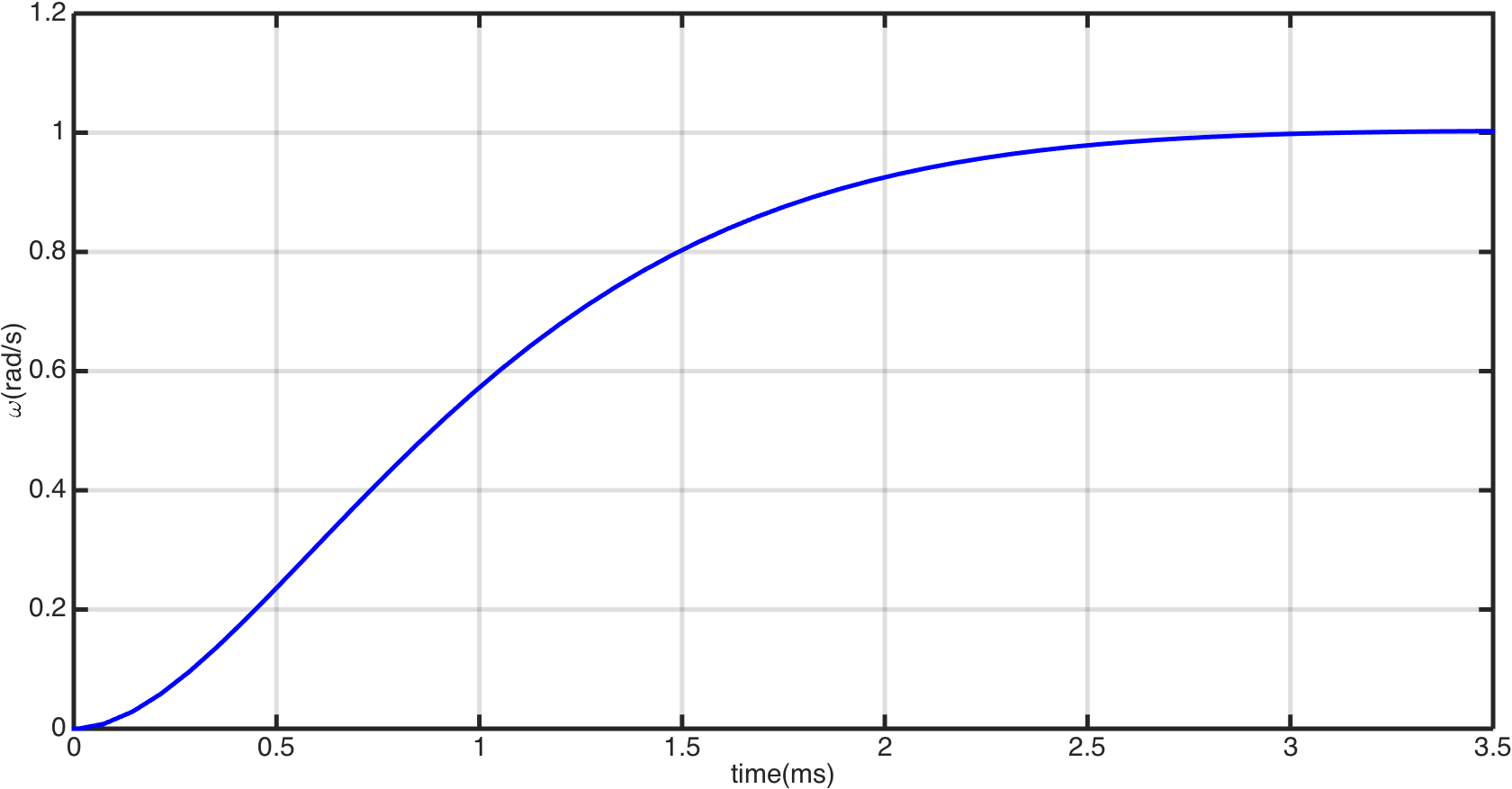
When the damping ratio ξ𝜉\xi is chosen to be 0.88, the coefficients of the proportional-integral controller are Kpv=0.26,Kiv=53.5formulae-sequencesubscript𝐾𝑝𝑣0.26subscript𝐾𝑖𝑣53.5{K_{pv}}={\rm{0}}{\rm{.26}},{K_{iv}}={\rm{53}}{\rm{.5}}. The step response of velocity closed loop system is shown in Fig. 6. The rise time of the velocity closed loop system is within 0.002s, almost no overshoot, can meet the requirements of a velocity source.
Refer to caption
Figure 6: Step response of the velocity control

IV-B Simulation Results of the Torque Control

The transfer function P(s)𝑃𝑠P(s) from ωd(s)subscript𝜔𝑑𝑠\omega_{d}(s) to To(s)subscript𝑇𝑜𝑠T_{o}(s) when the load is fixed is:

P(s)=0.2034s3+245.1s2+2.848e06s+5.761e08s4+3340s3+3.817e06s2+6.54e08s𝑃𝑠0.2034superscript𝑠3245.1superscript𝑠22.848𝑒06𝑠5.761𝑒08superscript𝑠43340superscript𝑠33.817𝑒06superscript𝑠26.54𝑒08𝑠P(s)=\frac{{0.2034{s^{3}}+245.1{s^{2}}+2.848e06s+5.761e08}}{{{s^{4}}+3340{s^{3}}+3.817e06{s^{2}}+6.54e08s}}
Refer to caption
Figure 7: Torque control structure for the cable-driven SEA.

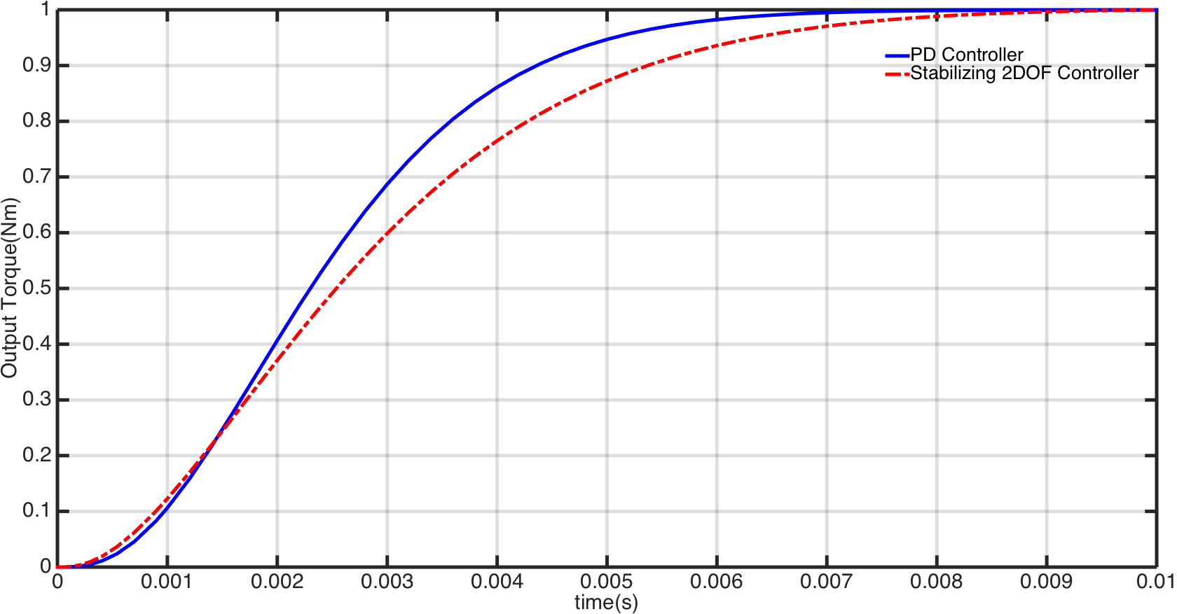
The stabilizing 2-DOF controller can be obtained by choosing ω¯n=451.24subscript¯𝜔𝑛451.24\bar{\omega}_{n}=451.24 and ξ¯=0.826¯𝜉0.826\bar{\xi}=0.826. In the simulation, a PD controller CPD(s)=490+0.1ssubscript𝐶𝑃𝐷𝑠4900.1𝑠{C_{PD}}(s)=490+0.1s is used for comparison. The torque control structure for the cable-driven SEA is shown in Fig. 7.

In the first simulation, the disturbance d𝑑d and the noise n𝑛n are set to zero. Then, the step responses from Td(s)subscript𝑇𝑑𝑠T_{d}(s) to To(s)subscript𝑇𝑜𝑠T_{o}(s) of the two control method are shown in Fig. 8. Both the two method tracks the step input quickly and accurately.
Refer to caption
Figure 8: Tracking step signal without disturbance and noise

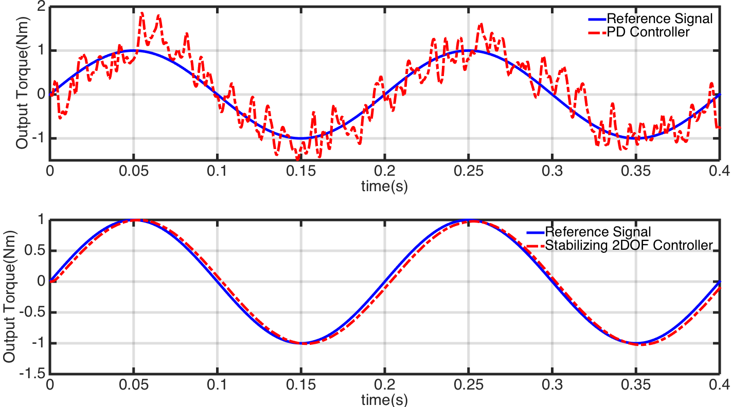
In the second simulation, the disturbance d𝑑d and the noise n𝑛n are set as gaussian white noises with zero mean. The input signal Tdsubscript𝑇𝑑T_{d} is set as a sinusoidal signal with frequency of 5 Hz and amplitude of 1 Nm. The tracking results are shown in Fig. 9. It is clear that the stabilizing 2-DOF controller can enhance the system robustness.
Refer to caption
Figure 9: Tracking sinusoidal signal with disturbance and noise

V Conclusions

This paper demonstrates the efficacy of the 2-DOF control approach for the challenging torque control problem of a cable-driven SEA. The 2-DOF torque controller performed better compared with the PD method in the presence of noise and disturbance in the simulations. The torque control performance can be conveniently adjusted by choosing appropriate filter Q1(s)subscript𝑄1𝑠Q_{1}(s) and Q2(s)subscript𝑄2𝑠Q_{2}(s).

Further research will be focused on the impedance control of the cable-driven SEA.

References

  • [1] G. A. Pratt and M. M. Williamson, “Series elastic actuators,” in Proceedings of the IEEE/RSJ International Conference on Intelligent Robots and Systems, vol. 1, 1995, Conference Proceedings, pp. 399–406.
  • [2] D. W. Robinson, J. E. Pratt, D. J. Paluska, and G. Pratt, “Series elastic actuator development for a biomimetic walking robot,” in Proceedings of the IEEE/ASME International Conference on Advanced Intelligent Mechatronics, 1999, Conference Proceedings, pp. 561–568.
  • [3] K. Kong, J. Bae, and M. Tomizuka, “A compact rotary series elastic actuator for human assistive systems,” IEEE/ASME Transactions on Mechatronics, vol. 17, no. 2, pp. 288–297, 2012.
  • [4] H. Yu, S. Huang, N. V. Thakor, G. Chen, S. L. Toh, M. S. Cruz, Y. Ghorbel, and C. Zhu, “A novel compact compliant actuator design for rehabilitation robots,” in Proceedings of the IEEE International Conference on Rehabilitation Robotics, 2013, Conference Proceedings, pp. 1–6.
  • [5] D. Chapuis, R. Gassert, G. Ganesh, E. Burdet, and H. Bleuler, “Investigation of a cable transmission for the actuation of MR compatible haptic interfaces,” in Proceedings of the First IEEE/RAS-EMBS International Conference on Biomedical Robotics and Biomechatronics, 2006, Conference Proceedings, pp. 426–431.
  • [6] R. J. Caverly, J. R. Forbes, and D. Mohammadshahi, “Dynamic modeling and passivity-based control of a single degree of freedom cable-actuated system,” IEEE Transactions on Control Systems Technology, vol. 23, no. 3, pp. 898–909, 2015.
  • [7] J. F. Veneman, R. Ekkelenkamp, R. Kruidhof, F. C. V. D. Helm, and H. V. D. Kooij, “A series elastic-and bowden-cable-based actuation system for use as torque actuator in exoskeleton-type robots,” The International Journal of Robotics Research, vol. 25, no. 3, pp. 261–281, 2006.
  • [8] J. Oblak, I. Cikajlo, and Z. Matjac̆ić, “Universal haptic drive: A robot for arm and wrist rehabilitation,” IEEE Transactions on Neural Systems and Rehabilitation Engineering, vol. 18, no. 3, pp. 293–302, 2010.
  • [9] F. Sergi and M. K. O’Malley, “On the stability and accuracy of high stiffness rendering in non-backdrivable actuators through series elasticity,” Mechatronics, vol. 26, pp. 64–75, 2015.
  • [10] D. W. Robinson, “Design and analysis of series elasticity in closed-loop actuator force control,” Thesis, Massachusetts Institute of Technology, 2000.
  • [11] G. Wyeth, “Control issues for velocity sourced series elastic actuators,” in Proceedings of the Australasian Conference on Robotics and Automation, 2006, Conference Proceedings.
  • [12] H. Vallery, R. Ekkelenkamp, H. V. D. Kooij, and M. Buss, “Passive and accurate torque control of series elastic actuators,” in Proceedings of the IEEE/RSJ International Conference on Intelligent Robots and Systems, 2007, Conference Proceedings, pp. 3534–3538.
  • [13] D. Accoto, G. Carpino, F. Sergi, N. L. Tagliamonte, L. Zollo, and E. Guglielmelli, “Design and characterization of a novel high-power series elastic actuator for a lower limb robotic orthosis,” International Journal of Advanced Robotic System, vol. 10, p. 359, 2013.
  • [14] K. Kong, J. Bae, and M. Tomizuka, “Control of rotary series elastic actuator for ideal force-mode actuation in human-robot interaction applications,” IEEE/ASME Transactions on Mechatronic, vol. 14, no. 1, pp. 105–118, 2009.
  • [15] S. Yoo and W. K. Chung, “SEA force/torque servo control with model-based robust motion control and link-side motion feedback,” in Proceedings of the IEEE International Conference on Robotics and Automation, 2015, Conference Proceedings, pp. 1042–1048.
  • [16] J. Lu, K. Haninger, W. Chen, and M. Tomizuka, “Design and torque-mode control of a cable-driven rotary series elastic actuator for subject-robot interaction,” in Proceedings of the IEEE International Conference on Advanced Intelligent Mechatronics, 2015, Conference Proceedings, pp. 158–164.
  • [17] I. M. Horowitz, Synthesis of feedback systems.   London: Acdemic Press, 1963.
  • [18] L. Qiu and K. Zhou, Introduction to feedback control.   New Jersey: Pearson Prentice Hall, 2010.
  • [19] P. Huang, “Theoretical and experimental studies on two-degree-of-freedom controllers,” Thesis, Hong Kong University of Science and Technology, 2015.
  • [20] W. Zou, W. Tan, Z. Yang, and N. Yu, “Torque control of a cable-driven series elastic actuator using the 2-DOF method,” in Proceedings of the Chinenese Control Conference, 2016, Conference Proceedings, pp. 6239–6243.
  • [21] W. Zou, Z. Yang, W. Tan, M. Wang, J. Liu, and N. Yu, “Impedance control of a cable-driven series elastic actuator with the 2-DOF control structure,” in Proceedings of the IEEE/RSJ International Conference on Intelligent Robots and Systems, 2016, Conference Proceedings, pp. 3347–3352.
  • [22] W. Zou, W. Tan, Z. Yang, and N. Yu, “Augmented virtual stiffness rendering of a cable-driven SEA for human-robot interaction,” The IEEE/CAA Journal of Automatica Sinica, 2017.