Source Code Verification for Embedded Systems using Prolog
Abstract
System relevant embedded software needs to be reliable and, therefore, well tested, especially for aerospace systems. A common technique to verify programs is the analysis of their abstract syntax tree (Ast). Tree structures can be elegantly analyzed with the logic programming language Prolog. Moreover, Prolog offers further advantages for a thorough analysis: On the one hand, it natively provides versatile options to efficiently process tree or graph data structures. On the other hand, Prolog’s non-determinism and backtracking eases tests of different variations of the program flow without big effort. A rule-based approach with Prolog allows to characterize the verification goals in a concise and declarative way.
In this paper, we describe our approach to verify the source code of a flash file system with the help of Prolog. The flash file system is written in C++ and has been developed particularly for the use in satellites. We transform a given abstract syntax tree of C++ source code into Prolog facts and derive the call graph and the execution sequence (tree), which then are further tested against verification goals. The different program flow branching due to control structures is derived by backtracking as subtrees of the full execution sequence. Finally, these subtrees are verified in Prolog.
We illustrate our approach with a case study, where we search for incorrect applications of semaphores in embedded software using the real-time operating system Rodos. We rely on computation tree logic (Ctl) and have designed an embedded domain specific language (Dsl) in Prolog to express the verification goals.
1 Introduction
Embedded systems are heavily used in mission critical parts, e.g. in the field of aerospace. Therefore, established and time-proven software is preferred to modern cutting-edge technology. Thus, new software concepts must be well tested and approved before it is applied in critical missions.
The majority of software in embedded systems is written in the two programming languages C (51 %) and C++ (30 %) [13]; both are often processed by the same tools such as Clang/Llvm. In a satellite project, we have developed a tailored file system for the embedded use on a satellite. It makes use of several flash memory chips and one Mram, a non-volatile random access memory. The file system is a module for the real-time operating system Rodos 111Real-time On-board Dependable Operating System: http://www.dlr.de/irs/desktopdefault.aspx/tabid-5976/9736_read-19576/, which is developed at the German Aerospace Center (Dlr) and the chair for aerospace information system at the university of Wuerzburg. Like Rodos, we have written the file system in C++. To improve the correct implementation, we want to verify the file system formally. In extend to general-purpose static analyses of software, we plan to test domain specific patterns for the file system.
Verification Goals
For our first approach of verification, in this paper, we pick one aspect of using operating systems: the application of semaphores.
Nonetheless, our approach can be adapted to test for other verification goals.
Rodos provides semaphores as classes with the methods enter and leave.
Both methods have no return values (void).
However, the method enter blocks if the semaphore has been entered previously.
Usually, a programmer uses semaphores by directly accessing its instance variable.
Semaphores are used for synchronizing concurrent threads in Rodos; as long as a semaphore is entered and not left no thread can enter it a second time.
The semaphore sema is entered once and left, eventually.
However, semaphores can be used wrongly.
Entering a semaphore without leaving it is an example for an incorrect usage.
void Test::methodC() {methodE();sema.leave();}void Test::methodD() {methodE();}void Test::methodE() {methodF();sema.enter();methodG();}void Test::methodF() { }void Test::methodG() { }
We start with the invocation of methodC.
It first calls methodE which enters the semaphore.
Then, methodE is left while keeping the semaphore entered.
After returning to methodC the semaphore is left.
Therefore, for methodC, the semaphore is used correctly.
However, if methodD is invoked, it only calls methodE which enters the semaphore.
After that, the execution returns from methodE to methodD.
However, there are no other calls within methodD.
Thus, if the semaphore will not be left after returning from methodD, then there is an incorrect usage of semaphores.
Consequently, we have to analyze the sequence of method calls to check the correct application of semaphores.
Overview of the Verification Process
The basis for our investigation is the source code of the software; we transform it into different graph representations in subsequent stages. Figure 1 outlines the stages and graphs.
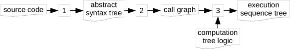
At first, a converter using Clang transforms the corresponding abstract syntax tree (Ast) into Prolog facts. Secondly, declarative Prolog rules match graph patterns of method calls within the Ast and extract information about method calls into a call graph (Cg). In the last stage, traversing Prolog rules construct execution sequence trees (Est). Ests contain information about method calls that are sequentially executed after a given method call. Based on user-defined computation tree logic (Ctl) propositions and different program flows in the software, the process generates different non-deterministic variations of the Est, which we call non-deterministic execution sequence trees (Nest). The traversing process simultaneously evaluates the Ctl propositions on the nodes during the construction of the Nest; therefore, it detects Nests with failing or successful Ctl checks early and, thus, aborts the creation prematurely. This reduces the number of Nests that are investigated eventually.
Using Prolog for Verification
Similar to JTransformer[12], which operates with Prolog on Java source code, we want to perform static source code analyses by using Prolog rules – but for C/C++ software. This paper shows our first attempt of source code verification for embedded software using non-deterministic Prolog rules. We use Prolog for several reasons. Firstly, we are able to extend the analysis by writing comprehensible Prolog rules. Secondly, Prolog enables an easy definition of domain specific languages to match the requirements of specific software parts, e.g. file systems. Thirdly, as we heavily operate on graph structures, we can use existing graph investigation techniques and libraries which are already available in Prolog systems. Additionally, we use non-determinism in Prolog. Control structures in source code lead to different branches of the program flow at runtime, depending on their evaluation results. We use Prolog’s backtracking mechanism to test several variants of program flows for the verification goals. For our implementation we use the established Prolog system Swi-Prolog [16].
Organization of the Paper
The remainder of this paper is organized as follows. Section 2 describes the representation of the source code as abstract syntax tree. From the abstract syntax tree we extract in Section 3 a call graph for methods. For the investigation of subsequent calls, we create in Section 4 an execution sequence tree. Based on the execution sequence tree, the control structures in the source code and the verification goals, we generate different non-deterministic execution sequence trees. In Section 5 we define appropriate computation tree logic propositions to analyze the usage of semaphores. Section 6 summarizes other approaches that use logic programming for software verification. Finally, we conclude in Section 7 with an outlook to future work.
2 Representation of the Abstract Syntax Tree in Prolog
At the first stage (stage 1 in Figure 1) a converter translates the source code’s structure into an Ast as Prolog facts. To extract the Ast from the source code the converter uses Clang, a C/C++ front end for Llvm 222Low Level Virtual Machine: http://llvm.org. The converter consists of about 190 lines of C code, and translates every node from the Ast into Prolog facts with the same structure, independent of its type. Using the same fact structure eases processing the full Ast without paying attention to the types. The resulting facts (Ast nodes) have the following structure:
node(File, Ast_Order, Id, Par_Id, Type, Src_Loc, Params).
For every C/C++ source file, Clang creates a separate Ast.
The node IDs are unique within a single Ast.
Our verification process, however, operates on the complete Ast of the full software, thus, it merges all the individual Asts.
To keep the nodes unique, the converter extends them by the name (path) of the source file on which a single Ast bases (File, first argument of node/7).
The second argument (Ast_Order) defines the relative location of a node among its siblings.
It is an integer value starting with 0 among the siblings.
The argument Id represents the identifier of the node within a source file’s Ast, and Parent_Id is the identifier of its parent node in the same Ast.
The fifth argument (Type) names the node Type (e.g. IfStmt, CXXMethodDecl).
The argument Src_Loc contains the location of the node within the source code given by its file name, the line and the column of the first character as well as its range.
However, not every node contains the complete information about its location.
There are some information (e.g. the source file name) that have to be obtained from the ancestor nodes.
Depending on its Type, a node comes with specific parameters which differ in number and in data types.
However, the converter translates every node into the same fact structure.
This enables a consistent processing of the Ast.
Thus, the additional information is saved in the last element (Parameters) as a Prolog list which contains the specific extra information.
For accessing the extra information, particular access rules are defined (see end of Section 2).
Example Representation of a Source Code as an Ast
Apart from the syntactical structure of the source code, Clang additionally includes references that describe semantic links between nodes of the Ast.
Figure 2 shows an Ast for the file test.cpp from the following source code:
// File: test.hclass Test {public:bool var;void methodA();void methodB();void methodC();};// File: test.cpp#include "test.h"void Test::methodA() {methodC();if(var) methodB();}void Test::methodB() {methodC();}void Test::methodC() { }
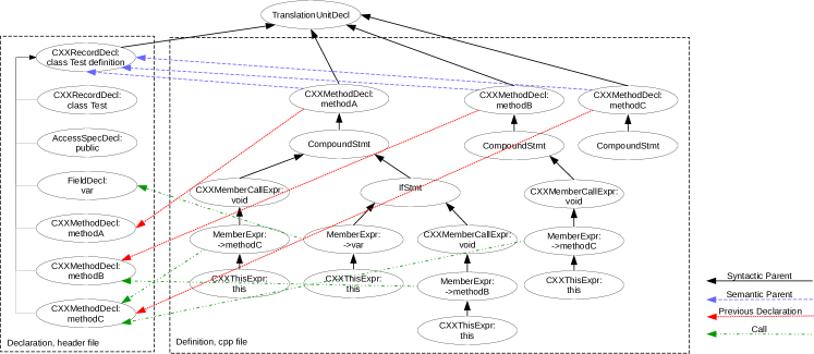
The type of the root node is always TranslationUnitDecl.
Due to #include statements in the source file, Clang adds nodes from additional files, usually header files, to the Ast.
In the example, the Ast contains nodes from a source and a header file; Figure 2 separates the nodes by their origin (dashed boxes).
The header file declares the class Test (node CXXRecordDecl333The prefix CXX in the types of the nodes stands for C++.), the member variable var (node FieldDecl) and the three methods methodA, methodB, and methodC (nodes CXXMethodDecl).
The implementations (definitions) of the methods are written in the source file, and not the header file.
Therefore, the method declaration nodes CXXMethodDecl from the header file lack syntactic children (black edges).
Instead, they have semantic children (blue edges) that describe their implementations (definitions).
The implementations (definitions) of the methods, though, are syntactical children of the root node (TranslationUnitDecl).
The body of a method is always enclosed in curly braces; the CompoundStmt stands for this enclosed compound of statements.
Consequently, the children of CompoundStmt describe the method’s body.
A method call is defined by three subsequent nodes; CXXMemberCallExpr specifies the return type, MemberExpr describes the member name (method or variable), and CXXThisExpr defines the variable (object) on which the call or access is executed.
Additionally, Clang adds a reference to the declaration of the called method to the MemberExpr nodes (green edges).
Moreover, if a method is already declared before, Clang adds a reference from the CxxMethodDecl to the previous declaration node (also CxxMethodDecl, red edges).
The methodA calls one or two other methods; methodC is always called whereas the call of methodB depends on the evaluation result of the if statement.
The left child of the node IfStmt defines the condition part, and the right child defines the then part.
Thus, the call of methodB is only executed if the value of var is true.
Regarding the extra (colored) edges, the resulting structure, actually, is not a tree; instead, it is a directed acyclic graph (Dag). As mentioned above, the process in the first stage transforms the Ast from Clang into Prolog facts. Here are some example nodes:
% node(+File, +AST_Order, +Id, +Par_Id, +Type, +Src_Loc, +Params) <-node( ’src/test.cpp’, 4, ’0x2b8e2a0’, ’0x2b8d8f0’, ’CXXRecordDecl’,’<data/src/test.cpp:1:1, line:13:1>’,[’class’, ’Test’, ’definition’] ).node( ’src/test.cpp’, 7, ’0x2b8e4c0’, ’0x2b8e2a0’, ’CXXMethodDecl’,’<line:3:3, line:6:3>’,[’methodA’, ’void (void)’] ).
Prolog Rules for Accessing Ast Structures
For an easy access to the Ast we define several rules.
Two predicates are used for accessing syntactic relations; edge/3 represents the syntactic edges of the Ast, and transitive/3 determines ancestors or descendants of nodes.
Additionally, we define particular predicates for accessing the different node types.
As mentioned in a previous paragraph, different types of nodes include different extra information in the list Parameters.
The rules extract the extra information and provide them as arguments of the predicate.
The following example shows the rules for edge/3, transitive/3, if_stmt/3, and member_expr/5.
% edge(-File, -Parent, -Child) <-edge(File, Parent, Child) :-node(File, _, Child, Parent, _, _).% transitive(-File, -Ancestor, -Child) <-transitive(File, Ancestor, Child) :-edge(File, Ancestor, Child).transitive(File, Ancestor, Child) :-edge(File, Parent, Child),transitive(File, Ancestor, Parent).% if_stmt(-File, -Id, -AST_Order) <-if_stmt(File, Id, AST_Order) :-node(File, AST_Order, Id, _, ’IfStmt’, _).% member_expr(-File, -Id, -AST_Order, -Name, -Callee_Id) <-member_expr(File, Id, AST_Order, Name, Callee_Id) :-node(File, AST_Order, Id, _, ’MemberExpr’, Parameters),append(_, [Name, Callee_Id], Parameters).
The predicate if_stmt/3 represents a node with the type IfStmt.
The predicate member_expr/5 represents a node with the type MemberExpr, which describes the access to a member variable or method.
The rule extracts the name and the ID of the called method (Callee_Id) from the list Parameters.
3 Call Graph in Prolog
The Ast, created by Clang, provides references from calling methods to the called methods, see Section 2. Using this information we generate a graph that only contains information about method calls. We name the graph call graph (Cg), which can be expressed as
with
-
•
defines the graph structure with a set of nodes and a set of edges .
-
•
defines additional information for the nodes and edges; is a set of method names, is a set of locations within the source code, is a set of variable names; is a labeling function , is a labeling function , and is a labeling function
-
•
defines the nodes’ dependence on conditions (control structures); is a set of condition IDs, and is a labeling function with .
For the investigation of different program flows, we use information about control structures.
Either one or several nested control structures within method bodies decide whether a method call is skipped.
The transformation process labels the edges with a set of control structure IDs that affect the method call.
Some control structures like if ensure an exclusive execution of their children.
For example, the control structure if executes either the then part or the else part – never both parts at the same time.
To cover the exclusive execution, the labeling function assigns the ID of the control structure as well as an identifier of the branching.
For example, the nodes of the then part are categorized with the same ID of the if node and the same branch ID 0; the nodes of the else part have the same ID of the if, but a different branching ID 1.
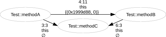
Figure 3 shows the resulting Cg for the Ast from Figure 2. The nodes are labeled with the methods’ names. The edges are labeled with the source code location, the variable (object) name on which the call is invoked, and the set of the control structure and branch IDs they depend on.
Detection Rules for Code Patterns of Methods
Information about code structures like method declarations, their definitions, method calls etc. is stored within the Ast. The information is not available in single nodes, but rather in subgraph structures of the Ast. In Prolog, we define graph patterns especially for structures like method definition, method calls etc. The following example shows rule that detects the declaration of a method.
% method_decl(-File, -Method_Id, -Full_Name) <-method_decl(File, Method_Id, Full_Name) :-cxx_method_decl(File, Method_Id, Func_Name, _),transitive(File, Class_Id, Method_Id),cxx_record_decl(File, Class_Id, ’class’, Class_Name),namespace(File, Method_Id, Namespace_Name),atomic_list_concat([Namespace_Name, ’::’, Func_Name], Full_Name).
Generally, the rule searches for a class definition which contains a method definition.
The rule seeks a pattern that consists of a node CXXMethodDecl (predicate cxx_method_decl/4) and an ancestor node CXXRecordDecl (predicate cxx_record_decl/4) with the record type ’class’.
The node for the method, CXXMethodDecl, contains only the local name of the method, not the full one.
To obtain the full name, the rules of namespace/3 recursively traverse the Ast up and joins the appropriate scope names (e.g. from classes or namespaces).
After that, atomic_list_concat/2 merges the resulting prefix and the local name.
Detection Rules for Control Structures
There are different types of structures that lead to conditional execution of operations.
On the one hand there are obvious keywords for control structures such as do, for, if, while and the ternary operator ?.
On the other hand there are structures which implicitly skip operations.
For example, an or (||) executes the second operand only if the first one is false.
Otherwise the second operand is not executed at all (short-circuit evaluation).
We define rules that identify control structures and determine the root nodes of the conditionally executed subtrees.
The following example shows a rule extracting an if statement with a then part and an else part:
% if(-File, -Cond_Id, -Then_Id, -Else_Id) <-if(File, Cond_Id, Then_Id, Else_Id) :-if_stmt(File, Id, _),node(File, 1, Cond_Id, _, _, _),edge(File, Id, Cond_Id),node(File, 2, Then_Id, _, _, _),edge(File, Id, Then_Id),node(File, 3, Else_Id, _, _, _),edge(File, Id, Else_Id).
The rule seeks a node IfStmt (predicate if_stmt/3) and its three children.
The three children are the root nodes of subtrees that stand for the different parts of the if; the first subtree represents the condition part, the second subtree represents the then part, and the third subtree represents the else part.
The order of the children defines their assignment to the parts of the if; therefore, they are determined by their order 1 to 3 in node/6.
We also defined a similar rule for ifs without an else part, which is not shown in this paper.
Virtual Methods
An important feature of the object-oriented programming paradigm is the inheritance of classes.
Subclasses can overwrite methods if the method is declared as virtual in the superclass.
Due to inheritance, a pointer for a superclass can also point to a corresponding subclass.
Then, if an overwritten method is called, the implementation in the subclass is called instead of the one in the superclass.
As mentioned in Section 2, nodes that represent method calls refer to the declaration of the called method.
However, it always points to the method of the pointer’s type, not to overwritten methods.
Thus, we generate multiple Cgs that call overwritten methods instead.
4 Building Execution Sequence Trees in Prolog
The verification process investigates consecutive method calls that are executed after a given method call. A tree structure, which we name Execution Sequence Tree (Est), represents the subsequent method calls. To create an Est, the generator preforms a depth-first search on the Cg. Beginning from the given method call and regarding the program flow, the subsequent method calls (successor nodes) are added sequentially as a list to the Cg. After traversing the successor nodes, the generator visits the parent nodes of the given method call. The parent nodes represent calling methods and, therefore, a return back to the calling methods. Each parent leads to a branching in the Est, which represent different program flows.
Definition of Execution Sequence Trees
The tree structure Est can be expressed as
where
-
•
defines the graph structure with a set of nodes and a set of edges ,
-
•
defines additional information for nodes and for edges; is a set of method names, is a set of locations within the source code, is a set of variable names; is a labeling function , is a labeling function , is a labeling function , and is a labeling function for the set of call types: child (), parent (), and root (),
-
•
defines which nodes depend on conditions (control structures); is a set of conditions IDs and is a labeling function with .
An Est is specifically created for a given method call (edge within the Cg). At first, the calling method is used as root node including the information about the call, i.e. the location in the source code and the variable (object) name. The node becomes the active branch of the Est. According to the program flow, traversing rules add subsequent method calls to the active branch with regard to the following guidelines:
- Children
-
Coming from the entry edge, the current node is added to the active branch of the Est including the information of the entry edge. After that, all successors are traversed in a depth-first search, whereby siblings are ordered by their location within the source code.
- Parents
-
After processing all children or detecting a return node, the traversing rules proceed to the parent nodes. They add each parent node to the last node of the active branch of the Est. As a result, the traversing rules create new branchings which then are separately processed (becoming active), beginning with the children.
- Recursion
-
To avoid infinite loops in the traversing process, recursions are handled specially. If there is a recursion (direct or mutual method calls) within the Cg, then only one complete run is added to the active branch of the Est. After that, the depth-first search is aborted and backtracked to the next node after the entrance into the recursion. However, the information about which methods are called in the recursion remains in the Est due to the one complete run that was added.
In the Cg, information about conditions are assigned to the edges. To make the information also available in the Est, the transformation process adds it to the target node. Additionally, the information is propagated for all successors from the Cg and added to the nodes of the Est appropriately. Thus, the information about conditional execution of method calls is available for every node in the Est.
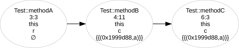
Keeping our example from Figure 3, Figure 4 shows two Ests which base on different calls of methodC.
Both resulting Ests are lists rather than dendritic tree structures, because of the simple running example.
The first EST (Subfigure (a)) bases on the method call methodAmethodC.
Consequently, methodA becomes the root node.
The depth-first search traverses all children that are called after the base call methodAmethodC.
The location in the source code of methodAmethodB (4:11) is greater than the base call methodAmethodC (3:3).
Therefore, methodB becomes the successor node in the Est.
After that, the process adds methodC to the Est because methodBmethodC is the next subsequent method call within methodB.
Then, no other subsequent method calls are left to add.
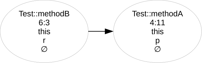
The second Est (Subfigure (b)) bases on the method call methodBmethodC.
Consequently, the method methodB becomes the root node.
There are no children in the Cg for methodB, therefore, it proceeds to the parent nodes and adds its parent methodA to the Est following the parent edge.
The process does not add any child nodes because the entry edge (4:11) is underneath the other method call methodAmethodC (7:3) in the source code.
Thus, there are no other nodes to add.
The generation process creates a set of term structures est_node/4 which defines the a full Est.
Terms of est_node/4 have the following structure:
The first parameter Id defines the identifier for the node within the Est.
Unlike in Cgs, a method call can exist more than once within the Est, therefore, using the method name is not enough for a unique identification.
Instead, the full path of method calls from the current node to the root node is used as the identifier.
This enables additionally an easy access of previous method calls.
The second and third parameters Location and Variable are the same values as from the Cg.
The last parameter Type is either r (root), c (child) or p (parent).
Bringing Non-Determinism to the Execution Sequence Tree
Control structures affect the execution of the software; some method calls are only executed in certain program flows. To investigate different program flows for programming errors, non-deterministic Prolog rules create variants (subtrees) of Ests, each representing a program flow. Due to the non-determinism in the creation process, we name a resulting variant of the Est non-deterministic execution sequence tree (Nest). A Nest for a given Est is identified by the set of valid (true) control structures and their branch IDs (e.g. then or else part). The set of nodes of a Nest is the union of the two sets and with
-
•
is the set of nodes which are present in every variation of Nests (deterministic), and
-
•
is the set of nodes which dependent on control structures. Therefore, it differs for every Nest variant.
The edges of a Nest are reduced according to the nodes. Only edges whose both nodes are part of the Nest become an edge of the Nest: . Additionally, if nodes are left out, their incoming edges are propagated as outgoing edges:
Accordingly, the same is true for more than one node left out in a row, as well.
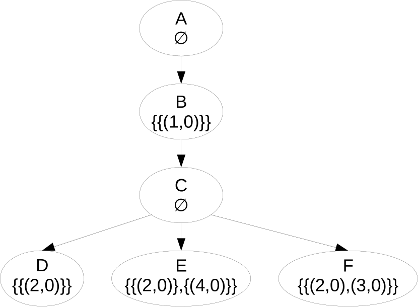
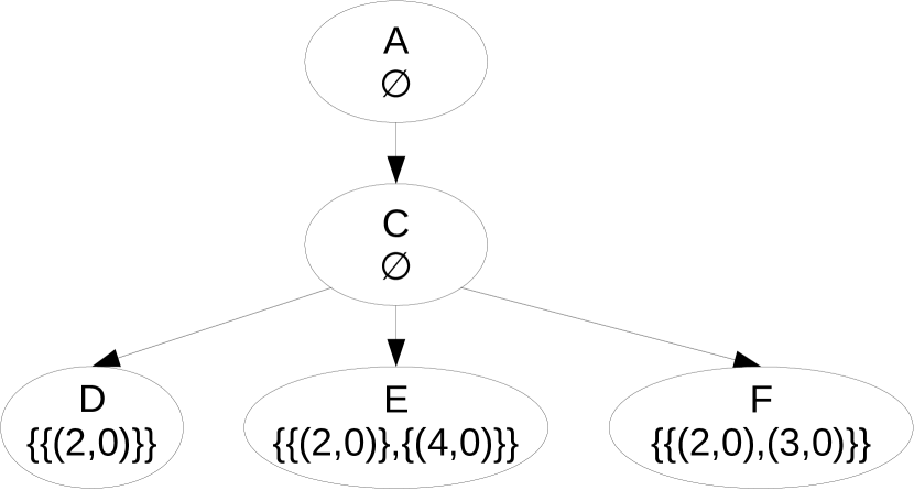
Figure 5 shows a complete Est and three variations of Nests.
For reasons of comprehensibility only the method names and the set of condition IDs are printed; other labellings are omitted.
The full Est in Subfigure (a) contains nodes with varying control structure dependencies.
The nodes B and D are valid for single conditions ((1,0) resp. (2,0)).
The node E depends on the two single conditions (2,0) and (4,0).
If one of the control structures is valid, node E becomes part of the Nest.
The node F is only included in a Nest if both conditions, (2,0) and (3,0), are valid.
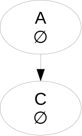
Subfigures (b) to (d) show different variants of Nests.
The Nest with no valid control structures is the least complex one.
It only contains nodes with empty sets of control structures, as Subfigure (b) shows.
Every node with a set of control structures that are valid for a Nest (in ), becomes part of the Nest.
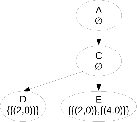
Subfigure (c) shows the Nest with one valid control structure: (2,0).
The Node F contains a combined set {(2,0),(3,0)}; however, the condition (3,0) is invalid, therefore, the node is left out.
For Nest of Subfigure (d) both, (2,0) and (3,0) are valid.
Consequently, nodes with only (2,0) (nodes D and E) and nodes with combined conditions (node F) are included in the Nest.
Limitation of the Range of Ctl Rules
Rules for Ctl check the properties of nodes in a tree. The number of checked nodes before the actual result is determined depends on the rules, on the properties of the nodes and on the quantifiers. The Table 1 gives an overview of the range of Ctl quantifiers. As soon as a success or a fail is determined, the Est creation stops and ignores the rest of the tree.
| Quantifier | Success | Fail | ||
|---|---|---|---|---|
| Condition | Ignored Nodes | Condition | Ignored Nodes | |
| AF | a node per path successes | remaining nodes per path | all nodes in a path fail | remaining paths |
| AG | all nodes success | none | one node fails | remaining nodes |
| AX | all next nodes success | none | a next node fails | remaining next nodes per path |
| AU | 1st stmt. successes until 2nd stmt. successes per path | remaining nodes per path | 1st and 2nd stmt. fail | remaining nodes |
| EF | one node successes | remaining nodes | all nodes in all paths fail | none |
| EG | all nodes for a path success | remaining paths | a node of the last path fails | remaining nodes of the last path |
| EX | a next node of a path successes | remaining nodes | next nodes in all paths fail | none |
Prolog rules traverse the Cg and construct the Nests, simultaneously applying the user-defined Ctl propositions. If the Ctl proposition success prematurely, the creation process aborts and proceeds with the next Nest. However, if the Ctl proposition fail, the process aborts and the user is informed about the problematic Nest. Consequently, the creation process for Nests neglects control structures that are only used in ignored subtrees; thus, the number of created Nests decreases.
5 Formulating Verification Goals for Semaphores
In Section 1 we presented semaphores, which are provided as classes in the operating system Rodos.
They are used by invoking their methods enter and leave.
We only analyze the static source code, therefore, there are limitations regarding variable values.
For example, we cannot detect whether two pointers refer to the same object, because we do not have access to the actual values.
However, semaphores in Rodos are usually accessed by using their object variable and seldom by using pointers.
Therefore, the static source code analysis is sufficient for our semaphore investigations.
Semaphore Entered but Never Left
The paragraph about verification goals in Section 1 illustrates an incorrect usage of semaphores: entering a semaphore without leaving it. We generate a Cg and consecutively derive an Est, based on the method call Test::methodESemaphore::enter.
Then, we apply a Ctl proposition on the Est:
On every branch of the Est (), finally (), the statement should be fulfilled: a node ought to have the method name = Semaphore::leave.
Additionally, the variable (object) name must be the same as the one from the root node (), to assure that the same semaphore is investigated.
In Prolog, we define Ctl statements as binary predicates.
The first argument is a term structure est_node/4 (see Section 4) of the root node in the Est, the second one is a term structure est_node/4 of the currently investigated node of the Est:
% sema_leave(+Root, +Node) <-sema_leave(Root, Node) :-Root = est_node(_, _, Var, _),Node = est_node([’Semaphore::leave’| _], _, Var, _).
The variable name (Var) has to be the same.
Additionally, the name of the called method must be Semaphore::leave.
This is done by peaking on the top element of the Id that represents the path of method names from the current node to the root node of the Est.
Semaphore Entered Several Times before Left
Secondly, we check whether a semaphore is entered twice or more often before it is left. An example clarifies the issue:
The semaphore sema is entered before and after the first call of methodB, but left only once, after the second call.
This programming error leads to an infinite blocking of the program at the second call of sema.enter().
To find this issue in the source code, we describe the correct usage in Ctl:
This Ctl proposition consists of two separate statement; for all branches () the first one must be true until () the second one becomes true.
The first statement expresses that the investigated node must not have the method name = Semaphore::enter with the same variable (object) name as the one of the root node ().
The second statement expresses that the investigated node must have the method name = Semaphore::leave on the same variable (object) name as the one of the root node ().
That means, that a semaphore should not be entered before it is left.
Above, we had already written the second statement in Prolog; the first statement in Prolog follows:
% sema_not_enter(+Root, +Node) <-sema_not_enter(Root, Node) :-Root = est_node(_, _, _, Var_1, _),Node = est_node(_, [Name_2| _], _, Var_2, _),( Var_1 \= Var_2; Name_2 \= ’RODOS::Semaphore::enter’ ).
This rule successes if the variable (object) names or the method names of the root and the current node differ.
6 Other Approaches Using Logic Programming for Verification
There exist several approaches which introduce logic programming into the static source code analysis of software. A brief comparison between logic-based infrastructures concerning detection and extraction is given by Kniesel, Hannemann and Rho [12], who compare different frameworks that enable software analysis and manipulation by an object-oriented program representation. The comparison addresses efficiency and scalability, but also further criteria such as expressiveness, turnaround and availability. The comparison also includes the formulation of a design pattern detection. They compare two frameworks for the analysis of Java source code: JQuery and their own approach JTransformer/CTC. CodeQuest was selected as a reference for performance and scalability. However, JTransformer is limited to process Java source code. There exists an extension to JTransformer, named StarTransformer444https://sewiki.iai.uni-bonn.de/research/jtransformer/api/meta/startransformer, which enables the analysis of other languages as well, but no application for C/C++ could be found yet. JTransformer is designed as a plug-in solely for the use with Eclipse555https://www.eclipse.org, a popular integrated development environment (Ide) for Java. But the development of embedded software often depends on different Ides or command line tools.
Consens and Mendelzon describe in various publications [7, 8] their query language named GraphLog. It operates on data represented as graph structures, even the queries are described as graph patterns. To evaluate a query the graph pattern is searched within the database graph. Data, queries and results can be visualized. The authors argue that many databases can be viewed as graphs. As a case study, they use GraphLog to analyze software structures in [9]. Consens et al. examine the package structure of a complex Windows application in order to remove cycles within the package dependency. However, the data structure for their software analysis is not the full Ast. Therefore, this approach is highly specialized and difficult to generalize.
Ciraci describes in his dissertation [5] the graph-based verification of static program constraints [6]. In the first step, the original source code is automatically converted into a intermediate representation which is called Scml (Source Code Modeling Language). Scml is an attributed graph representation of the source code. The Scml expressions can be imported directly from different languages – there are already converters for Java and C/C++. The constraints for the source code are described as graph transformation rules which also written in Scml. To notify the user for violated constraints, information nodes are inserted locally into the original Scml. The user can write Prolog rules to further investigate the information nodes. However, the program flow is not covered in Ciraci’s analysis.
Crew [10] created a Astlog, a Prolog-like programming language, to specifically process Asts. Astlog does not save a given Ast into an internal database, but references the elements of the Ast directly. A difference to a fact base in Prolog is the Current Object which only is implicitly available to rules. The rules are evaluated in the context of the Current Object; similar to a visitor in the visitor pattern. Even Astlog is Prolog-like, compatibility is not given.
Centaur [4] is a generic interactive debugging system. The input is a formal specification of the syntax and semantics of the used programming language. The specifications are described in Prolog which are used to convert the given source code into the internal data format (Virtual Tree Processor). Albeit Centaur provides an interactive investigation process, the automatic pattern recognition is not its main feature and therefore hard to modify.
Ballance, Graham and Van De Vanter present Pan [2], an integrated development environment, which allows to analyze source code loaded by its editor. They use logic programming in conjunction with Logical Constraint Grammars differently from Prolog. For instance, the logic database is partitioned into several collections and code in Pan is interpreted separated from data which makes it less flexible compared to homoiconic Prolog.
Wahler, Seipel, Von Gudenberg and Fischer propose an Xml structure for the representation of abstract syntax trees [15]. On that structure, they apply an algorithm inspired from data mining for searching clones within the source code by finding frequent itemsets in the Xml. In case studies they run the analysis on the Java Development Kit and the Dislog Development Kit. Additionally to the program analysis, the tool Squash of Boehm, Seipel, Sickmann and Wetzka can be used for designing, analyzing and refactoring relational database applications [3]. In their approach, schema definitions and queries from Sql are mapped to an Xml representation called SquashML. Like an Ast the Sql representation in SquashML is a tree structure. By using the Xml query and transformation language FnQuery, they use Prolog rules to describe modifications of the structure of the relational database. Additionally, Squash provides a visualization of the relations and join paths within Sql queries.
7 Conclusions and Future Work
Using Prolog provides a flexible and concise definition of verification goals. Furthermore, it enables the definition of domain-specific rules for validation. For future work, we intend to demonstrate the versatility by further evaluations for the flash file system. We aim at providing a verification that precisely addresses issues of flash file system, for example the retention of data in case of unpredicted failures. Using Prolog’s non-determinism enables the effortless investigation of different program flows. Additionally, we are interested in further applications of Prolog’s features like non-determinism for embedded software, beyond file systems.
The Est, which we introduced in Section 4, allows the application of Ctl for method calls in the program flow to investigate programming errors. By an early application of Ctl during the creation process of Nests, we already reduce the number of generated Nests. To further decrease the number of Nests, we are going to introduce further techniques such as Symbolic Execution to our process. Symbolic execution analyzes the domain of the values of variables, which reduces the non-determinism for control structures.
References
- [1]
- [2] Robert Ballance, Susan Graham & Michael Van De Vanter (1990): The Pan Language-based Editing System for Integrated Development. In: Proceedings of the Fourth ACM SIGSOFT Symposium on Software Development Environments, SDE 4, ACM, New York, NY, USA, pp. 77–93, 10.1145/99277.99286.
- [3] Andreas M. Boehm, Dietmar Seipel, Albert Sickmann & Matthias Wetzka (2007): Squash: A Tool for Analyzing, Tuning and Refactoring Relational Database Applications. In: Applications of Declarative Programming and Knowledge Management, 17th International Conference, INAP 2007, and 21st Workshop on Logic Programming, WLP 2007, Würzburg, Germany, October 4-6, 2007, Revised Selected Papers, pp. 82–98, 10.1007/978-3-642-00675-3_6.
- [4] Patrick Borras, Dominique Clement, Thierry Despeyroux, Janet Incerpi, Gilles Kahn, Bernard Lang & Valérie Pascual (1988): Centaur: The System. In: Proceedings of the Third ACM SIGSOFT/SIGPLAN Software Engineering Symposium on Practical Software Development Environments, SDE 3, ACM, New York, NY, USA, pp. 14–24, 10.1145/64135.65005.
- [5] Selim Ciraci (2009): Graph Based Verification of Software Evolution Requirements. Ph.D. thesis, Univ. of Twente, Enschede, 10.3990/1.9789036529563. CTIT Ph.D. thesis series no. 09-162.
- [6] Selim Ciraci, Pim van den Broek & Mehmet Aksit (2010): Graph-based Verification of Static Program Constraints. In: Proceedings of the 2010 ACM Symposium on Applied Computing, SAC ’10, ACM, New York, NY, USA, pp. 2265–2272, 10.1145/1774088.1774561.
- [7] Mariano Consens & Alberto Mendelzon (1990): GraphLog: A Visual Formalism for Real Life Recursion. In: Proceedings of the Ninth ACM SIGACT-SIGMOD-SIGART Symposium on Principles of Database Systems, PODS ’90, ACM, New York, NY, USA, pp. 404–416, 10.1145/298514.298591.
- [8] Mariano Consens & Alberto Mendelzon (1993): Low Complexity Aggregation in GraphLog and Datalog. In: Theoretical Computer Science 116, pp. 95–116, 10.1016/0304-3975(93)90221-E.
- [9] Mariano Consens, Alberto Mendelzon & Arthur Ryman (1992): Visualizing and querying software structures. In: International Conference on Software Engineering, IEEE, Melbourne, Australia, pp. 138–156, 10.1109/ICSE.1992.753496.
- [10] Roger Crew (1997): ASTLOG: A Language for Examining Abstract Syntax Trees. In: DSL, USENIX. Available at http://www.cs.nyu.edu/~lharris/papers/crew.pdf.
- [11] Martin Fowler (2010): Domain Specific Languages, 1st edition. Addison-Wesley Professional.
- [12] Günter Kniesel, Jan Hannemann & Tobias Rho (2007): A Comparison of Logic-based Infrastructures for Concern Detection and Extraction. In: Proceedings of the 3rd Workshop on Linking Aspect Technology and Evolution, LATE ’07, ACM, New York, NY, USA, 10.1145/1275672.1275678.
- [13] Mouaaz Nahas (2009): Bridging the gap between scheduling algorithms and scheduler implementations in time-triggered embedded systems. Ph.D. thesis, University of Leicester.
- [14] Dietmar Seipel, Rüdiger von der Weth, Salvador Abreu, Falco Nogatz & Alexander Werner (2016): Declarative Rules for Annotated Expert Knowledge in Change Management. In: Proceedings of the 5th Symposium on Languages, Applications, Technologies, SLATE 2016, OASICS, Dagstuhl Publishing, pp. 81–96, 10.4230/OASIcs.SLATE.2016.7.
- [15] Vera Wahler, Dietmar Seipel, Jurgen Wolff v. Gudenberg & Gregor Fischer (2004): Clone Detection in Source Code by Frequent Itemset Techniques. In: Proceedings of the Source Code Analysis and Manipulation, Fourth IEEE International Workshop, SCAM ’04, IEEE Computer Society, Washington, DC, USA, pp. 128–135, 10.1109/SCAM.2004.5. Available at https://dl.acm.org/citation.cfm?id=1022152&CFID=868270883&CFTOKEN=45278669.
- [16] Jan Wielemaker (2003): An overview of the SWI-Prolog Programming Environment. In Fred Mesnard & Alexander Serebenik, editors: Proceedings of the 13th International Workshop on Logic Programming Environments, Katholieke Universiteit Leuven, Heverlee, Belgium, pp. 1–16. Available at http://www.swi-prolog.org/download/publications/wlpe-03.pdf. CW 371.