Pseudo-Magnetic Quantum Hall Effect In Oscillating Graphene
Abstract
When a graphene layer is stressed, the strain alters the phase an electron accumulates hopping between sites in a way that can be modeled as arising from a pseudo-magnetic vector potential. We examine the case of an oscillating graphene ribbon and explore a new effect - an oscillating resistance arising from an oscillating quantum Hall effect. This pseudo-magneto-resistance is large, and depends upon the frequency and the amplitude of the acoustic oscillations. We calculate the consequences for experiment.
I Introduction
In 2004 Geim et al. isolated a single layer of graphite, setting off the discovery of a long list of remarkable properties of graphene, such as its great strength, high mobility, and linear electronic energy spectrum.GrapheneReview1 ; GrapheneReview2 One additional extraordinary property it displays is a strain-induced pseudo-vector potential.pseudoB1 The geometrical deformation of the monolayer graphene lattice introduces strain which can alter the phase difference between adjacent sites in a tight-binding model of the system. This phase difference can be viewed as arising from a “pseudo-magnetic field”.vectorpotential2 Such a pseudo-magnetic field does not break time reversal symmetry because it couples with opposite sign to electrons occupying different Dirac points in the band structure. One consequence of this was dramatically demonstrated by the observation of quantized Landau levels in strained graphene in the absence of an external magnetic field.qHallExpt1 This effect can be substantial: strain-induced vector potentials in static monolayer graphene have produced pseudo magnetic fields of 300 T.qHallExpt1
There has been much theoretical and experimental work done to study the pseudo-magnetic field created by strain applied to a static graphene layer.pseudoB3 ; pseudoB4 ; pseudoB5 ; pseudoB6 ; pseudoB7 ; pseudoB8 ; pseudoB9 ; pseudoB10 ; qHallExpt1 ; qHallExpt2 ; qHallExpt3 ; vectorpotential1 ; vectorpotential2 ; scalarPotential3 In this paper we will discuss the physics of a rapidly oscillating pseudo-magnetic field generated by an acoustically driven graphene ribbon. Typical electronic relaxation times in graphene are on the order of picoseconds.eeScatt ; relax If models developed for static lattice distortions are valid for the relatively “slow” acoustic oscillations, the system can potentially have pseudo-magnetic fields of several Tesla oscillating at a kilohertz. Such a regime is inaccessible for normal magnetic fields and opens up many new possibilities.
In this work we start with a review of the connection between pseudo-magnetic fields and applied strain. We then investigate oscillating pseudo-quantum Hall effect phenomena for low density graphene nano-ribbons with simulated experimental results for realistic parameters. The relevant experimental frequencies are quite low - indeed the adiabatic approximation gets better the lower the frequency is. For fixed frequency, the magnitude of the affect depends on the amplitude of the distortion giving a separate control for experiment. This independent control may allow investigation above and below the adiabatic limit. In this work we ignore the pseudo-electric field induced by strain. While in-plane electric fields can cause a collapse of Landau levels in graphene relax1 ; relax2 , the in-plane fields generated in this paper are small, and by appropriate choice of polarization can be minimized.
I.1 Basic Theory
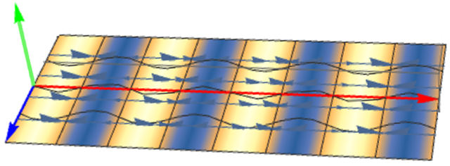
We consider an ideal 2D graphene nano-ribbon suspended between supports. The ribbon is driven acoustically by a piezoelectric transducer to produce a longitudinal standing wave. An atom at the position is displaced by vector (Fig.1)
| (1) |
producing a standing wave with displacements in the y direction. The stretching in the graphene layer produced by displacement produces a strain tensor which is given by
| (2) |
This strain tensor alters the phase difference between atoms in a tight-binding model of graphene in a fashion equivalent to one induced by a gauge field (pseudo-magnetic vector potential).pseudoB2 ; pseudoB3
| (3) |
where 1.4 Ao is the length of the bond between neighboring carbon atoms and and c are dimensionless parameters that are equal to 2 and 1 respectively.pseudoB1 The quantity is the valley pseudo-spin (called “valley spin” hereafter to avoid confusion with the layer index in multi-layer systems, which is also called “pseudo-spin”) , taken as at the point in the 2D bandstructure, and at the point. Therefore, even in the absence of a real magnetic field a strong pseudo-field is observed which comes from the curl of , but it is of opposite sign for electrons of opposite “valley-spin”. For the displacement of eq.(1) the magnetic field is given by
| (4) |
We have introduced a dimensionless strain amplitude f = . The strain amplitude is expressed as the ratio of the wave amplitude to a half wavelength, so that in terms of wave number, .
I.2 Oscillating quantum Hall magneto-resistance
We assume a suspended graphene nano-ribbon set up for a two-terminal measurement, driven with an acoustic oscillation of a wavelength on the order of several microns. The oscillation has a wavelength much longer than the coherence length of electrons in the system, and a frequency far less than the characteristic electron-electron scattering rate i.e. on the order of .eeScatt
(a)
(b)
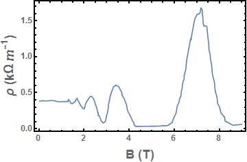
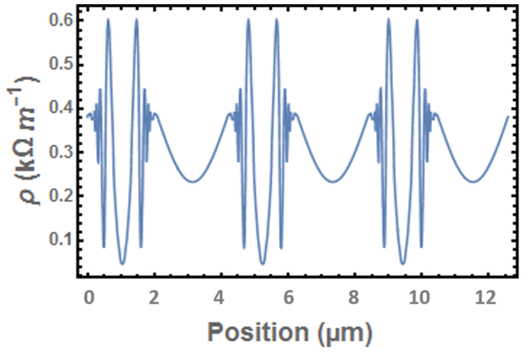
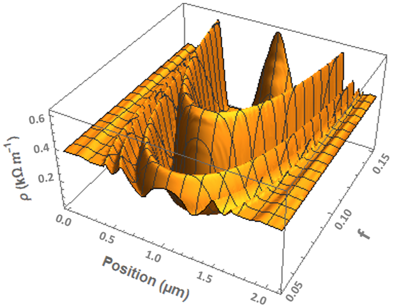
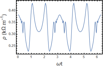
Since the acoustic oscllations of the ribbon are slow compared to the motion of the electrons, we treat each portion of the ribbon with displacement as an independent, equilibrium, quantum Hall “sample” with a magnetic field that is given by the pseudo-magnetic field of eqn.(4). The oscillating ribbon has pseudo-magnetic field that varies as a function of space as the effective strain amplitude, , varies in space. To obtain the longitudinal resistance for any positive or negative value of this oscillating pseudo-magnetic field, we use the value it would have in a uniform magnetic field using Fig.(2). Since the longitudinal resistance in quantum Hall systems is non-universal, we take a representative value from published experimental data janssen on graphene in Fig.(2). The oscillating strain produces a pseudo-magnetic field standing wave with a maximum amplitude that potentially can reach several Tesla. The resistivity obtained from the interpolation of Fig.(2) will therefore also oscillate in space and time, (Fig.3a). The oscillations of pseudo-field display more structure as the strain amplitude is increased, as shown in Fig.(3b)
It is important to note that this effect does not break time reversal symmetry. Electrons from different K-points see opposite signs of the pseudo-magnetic field, but the magneto-resistance is independent of the sign of the field, so both valley-spins polarizations are gapped (or not gapped) at exactly the same value of the strain.
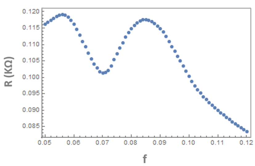
A more experimentally accessible property for a mechanically oscillating ribbon is its total resistance. For the oscillating monolayer graphene the total resistance at any point in time will be given by numerically integrating the resistivity graph of Fig.(3) along the length of the ribbon. If we choose a specific point in the oscillation, say when , we can calculate the expected resistance at that point as a function of strain amplitude. This calculated resistance varies non-monotonically as a function of strain amplitude as shown in Fig.(4). It oscillates because increasing the strain amplitude may allow the pseudo-magneto-resistance to reach a higher resistance peak in Fig.(2), increasing the total resistivity, but increasing the strain further brings it into a regime of lower resistivity while simultaneously reducing the width of the higher resistance region. The width is reduced because the entire range of the sweep of the pseudo-magnetic field must still fit within one wavelength, and increasing the strain amplitude does not change the wavelength of the oscillation. The lower minima in the oscillations at larger strain are a reflection of the fact that the experimental data for has deeper minima at larger fields.
Alternatively, we may plot the resistance of the ribbon as a function of time as the standing wave goes through one oscillation. If Fig.(3a) represents a slice of Fig.(3b) at constant strain amplitude , then the sinusoidal time dependence of the oscillation corresponds in effect to sweeping this slice from to the some maximum value and back. To get the resistance at any time we simply must integrate the corresponding slice along the direction. An example of a resistance trace as a function of time for a given strain amplitude is given in Fig.(5)
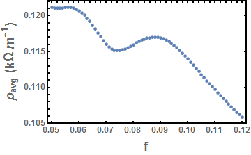
Finally, we may plot the time average of the resistance of the ribbon as a function of strain amplitude, as shown in Fig.(6). As can be seen from above, much detail of the structure will be lost by integrating the resistivity over both space and time. However, this is the simplest and most straightforward measurement that would show this fundamental quantum mechanical effect from an acoustic oscillation.
I.3 Conclusion
Experiments have already verified that a static strain in graphene can produce a pseudo-magnetic field of many Tesla. If the static distortion calculation is valid for the “slow” distortion of an acoustic wave, then pseudo-magnetic fields of several Tesla could be observed to oscillate at high frequency, a previously inaccessible regime of electron dynamics. We have investigated an oscillation in the resistance due to a quantum Hall-like effect produced from time dependent pseudo-magnetic field. This phenomena should be observable at experimentally accessible frequencies and temperatures. The absence of this phenomenon is equally intriguing since then the cross-over from the experimentally validated static theory to a time dependent distortion must itself be investigated.
Acknowledgements. K. M. was supported by NSF grant DMR-1310407.
References
- (1) Novoselov, Kostya S., et al. “Electric field effect in atomically thin carbon films.” science 306.5696 (2004): 666-669.
- (2) Novoselov, K. S., et al. “Two-dimensional atomic crystals.” Proceedings of the National Academy of Sciences of the United States of America 102.30 (2005): 10451-10453.
- (3) Guinea, F., Baruch Horovitz, and P. Le Doussal. “Gauge field induced by ripples in graphene.” Physical Review B 77.20 (2008): 205421.
- (4) F. Guinea, A. K. Geim, M. I. Katsnelson, and K. S. Novoselov, Phys. Rev. B 81, 035408 (2010).
- (5) Levy, N., et al. “Strain-induced pseudo–magnetic fields greater than 300 tesla in graphene nanobubbles.” Science 329.5991 (2010): 544-547.
- (6) Suzuura, Hidekatsu, and Tsuneya Ando. “Phonons and electron-phonon scattering in carbon nanotubes.” Physical review B 65.23 (2002): 235412.
- (7) Manes, Juan L. “Symmetry-based approach to electron-phonon interactions in graphene.” Physical Review B 76.4 (2007): 045430.
- (8) Morpurgo, A. F., and F. Guinea. “Intervalley scattering, long-range disorder, and effective time-reversal symmetry breaking in graphene.” Physical review letters 97.19 (2006): 196804.
- (9) Cortijo, Alberto, and Marıa AH Vozmediano. “Electronic properties of curved graphene sheets.” EPL (Europhysics Letters) 77.4 (2007): 47002.
- (10) de Juan, Fernando, Alberto Cortijo, and María AH Vozmediano. “Charge inhomogeneities due to smooth ripples in graphene sheets.” Physical Review B 76.16 (2007): 165409.
- (11) Morozov, S. V., et al. “Strong suppression of weak localization in graphene.” Physical review letters 97.1 (2006): 016801.
- (12) E. McCann, K. Kechedzhi, V. I. Fal’ko, H. Suzuura, T. Ando, and B. L. Altshuler, Phys. Rev. Lett. 97, 146805 2006
- (13) Gorbachev, R. V., et al. “Weak localization in bilayer graphene.” Physical review letters 98.17 (2007): 176805.
- (14) X. Wu, X. Li, Z. Song, C. Berger, and W. A. de Heer, Phys. Rev. Lett. 98, 136801 2007.
- (15) A. H. Castro Neto, N. M. R. Peres, K. S. Novoselov, and A. K. Geim, Rev. Mod. Phys., 81, 109. (2009)
- (16) Vozmediano, María AH, M. I. Katsnelson, and Francisco Guinea. “Gauge fields in graphene.” Physics Reports 496.4 (2010): 109-148.
- (17) Guinea, F., M. I. Katsnelson, and A. K. Geim. “Energy gaps and a zero-field quantum Hall effect in graphene by strain engineering.” Nature Physics 6.1 (2010): 30-33.
- (18) F. Guinea, A. K. Geim, M. I. Katsnelson, and K. S. Novoselov, Phys. Rev. B 81, 035408 (2010).
- (19) Guinea, F., M. I. Katsnelson, and M. A. H. Vozmediano. “Midgap states and charge inhomogeneities in corrugated graphene.” Physical Review B 77.7 (2008): 075422.
- (20) Tse, Wang-Kong, E. H. Hwang, and S. Das Sarma. “Ballistic hot electron transport in graphene.” Applied Physics Letters 93.2 (2008): 023128.
- (21) K. I. Bolotin, K. J. Sikes, Z. Jiang, M. Klima, G. Fudenberg, J. Hone, P. Kim, and H. L. Stormer, “Ultrahigh electron mobility in suspended graphene” Solid State Communications 146, 351-355 (2008).
- (22) Vicente Arjona, Eduardo V. Castro and Mar a A. H. Vozmediano, “Collapse of Landau levels in Weyl semimetals,” arXiv:1703.05399.
- (23) Lukose, V., Shankar, R. and Baskaran, G. “Novel electric field effects on landau levels in graphene,” Phys. Rev. Lett. 98, 116802 (2007).
- (24) Jiang, Z., et al. “Quantum Hall effect in graphene.” Solid State Communications 143.1 (2007): 14-19. “Reprinted from Solid state communications, Jiang, Z., et al., Quantum Hall effect in graphene, 14-19, Copyright (2017), with permission from Elsevier.”