A dual cavity Fabry-Perot device for high precision Doppler measurements in astronomy
Abstract
We propose a dual cavity Fabry-Perot interferometer as a wavelength calibrator and a stability tracking device for astronomical spectrograph. The FPI consists of two adjoining cavities engraved on a low expansion monoblock spacer. A low-finesse astro-cavity is intended for generating a uniform grid of reference lines to calibrate the spectrograph and a high-finesse lock-cavity is meant for tracking the stability of the reference lines using optical frequency standards. The differential length changes in two cavities due to temperature and vibration perturbations are quantitatively analyzed using finite element method. An optimized mounting geometry with fractional length changes is suggested. We also identify conditions necessary to suppress relative length variations between two cavities well below 10-10 m, thus facilitating accurate dimension tracking and generation of stable reference spectra for Doppler measurement at 10 cms-1 level.
keywords:
Wavelength calibration, Fabry-Perot cavity, Radial velocity method, Laser frequency locking, Thermal expansion and Vibration analysis†Corresponding author.
; ; ;
1 Introduction
High precision Doppler spectroscopy is an important tool to investigate many astrophysical processes in the Universe. Measurement of tiny Doppler shifts from radial velocity (RV) can provide insight about the stellar interior; reveal the existence of unseen planets around other stars; help us probe the variability of fundamental constants of nature and provide useful information of binary and pulsating stars Santos et al. (2006). In particular, the radial velocity technique has been immensely successful in detecting hundreds of planets with different mass range and orbital periods Marcy & Howard (2011). The main challenge and focus of contemporary research is to find Earth-analogs within the habitable zone of star where life sustaining conditions could prevail. Recently, the Doppler data from ESO’s two precision RV instruments, namely HARPS and UVES, was decisive in unveiling the presence of 1.3 Earth-mass rocky planet orbiting Proxima Centauri - the nearest known star to the Sun Anglada-Escudé at al. (2016).
Typically, Doppler precision of cms-1 or better is required to address many compelling science cases including the detection of terrestrial-size planets around sun-like stars Ujan (2011); Kim et al. (2009). Leading RV observing campaigns are carried out with state-of-the-art echelle spectrograph, carefully designed and built to operate under tightly regulated thermovac conditions Pepe et al. (2014); Fisher et al. (2016). A high resolution spectrum of star in visible/NIR band is recorded on a 2D array of CCD pixels. To extract the RV signal from time series data, spectrograph is wavelength calibrated with a laboratory source of well known emission or absorption lines. In calibration process several lines of known wavelengths are identified and a quadratic or high order polynomial fit is used to invert the pixel coordinates into accurate wavelength units.
Two commonly used wavelength reference in astronomy are thorium-Argon (Th-Ar) emission lamp and Iodine absorption cell Fischer et al. (2014). Despite averaging the shift over thousands of spectral lines, the best RV precision obtained from these sources is limited to ms-1. The RV uncertainty of traditional sources arises from wavelength inaccuracies of individual lines, spectral contamination, aging of the lamp, limited spectral coverage, line blending effects, uneven distribution and varying intensity of lines across spectrograph band Murphy et al. (2007).
An ideal calibrator choice for enabling sub-ms-1 RV precision in next generation spectrographs is a broadband laser frequency comb (LFC). The LFC consists of thousands of equispaced lines produced from a femtosecond mode-locked laser Murphy et al. (2007); Steinmetz et al. (2008). The entire comb spectrum is stabilized by anchoring to atomic clock with well established radio-frequency locking technique. Since past decade different versions of LFCs have been tested and validated Quinlan et al. (2010); Ycas et al. (2012); Probst et al. (2014). New developments are still awaited to overcome a couple of technical and operational difficulties. It might take a while for LFC to become a simple and affordable turn-key instrument for routine wavelength calibration at most observatories.
A simple and cost effective approach to produce reference spectra is to use cavity resonance lines of a FP etalon Wildi et al. (2012). A plane parallel FP cavity when illuminated with a broadband white light source acts as a periodic wavelength filter. The transmitted light consists of evenly distributed lines that result from multiple beam interference inside the cavity Vaughan (1989). The cavity lines are separated by free spectra range , where is the light speed and is the cavity length. Many variants of FPs (e.g. solid, air spaced and fiber based) have been successfully built and tested for astronomy calibration Schäfer & Reiners (2012); Halverson et al. (2014); Gábor et al. (2014); Florian et al. (2015).
The positional accuracy of FP lines critically depends on stability of the cavity itself. Any noise affecting the cavity length would randomly displace the resonant lines thus directly impairing the achievable RV precision. The impact of temperature and pressure fluctuations on the cavity length is generally eliminated by mounting the FP inside a thermally controlled evacuated chamber which is capable of achieving 1 ms -1 short-term stability Schäfer & Reiners (2012).
A passively stabilized FP apparatus producing reference spectra has no built–in mechanism to track systematic offsets or drifts in cavity length occurring over time scales of weeks, months or even years. Regardless of good passive isolation, cavity drift could still occur from temperature residuals, material aging or changes in optical properties of the coatings Riehle (1998); Fox (2009); Denus-Baillargeon et al. (2014). The radial velocity and the fractional length and frequency stability of the cavity can be expressed as . For instance, a 1 nm change in a 1 cm long cavity corresponds to 55 MHz frequency shift of cavity lines in visible ( nm) region, which amounts to 30 ms-1 RV uncertainty. To reach a RV precision cms-1, the cavity length should be stable to level or better.
For long-term usability (several months to years) of astro-FP, research efforts are now being directed at controlling and tracking the time dependent cavity drift with advance techniques Reiners et al. (2014); Schwab et al. (20015); Huke et al. (2015); Julian et al. (2016). Measurement of tiny dimensional changes in cavity length calls for advanced metrology based on laser frequency standards. A drift tracking or active length-control requires cavity-locking to a frequency stabilized diode laser or vice-versa Reiners et al. (2014). In cavity-lock setup, the frequency stability of the laser is expected to be transferred to the stability of the FP cavity lines. The main task of frequency or phase locking mechanism is to keep cavity transmission point in resonance with frequency of the laser Drever et al. (1983).
A short-length, low-finesse() cavity, while useful for generating broadband reference lines for astronomy spectrographs, is not ideal for laser metrology. Normally, a robust laser-lock requires a sharp discriminant signal which depends on the laser power and the cavity linewidth Black (2001). The linewidth of the cavity should be sufficiently narrow to produce a steeper error signal. The inverse dependence of and on the linewidth implies a clear advantage of longer and high finesse cavities. Another practical difficultly of utilizing astro-FP in laser applications is the cavity geometry. A confocal cavity design is more appropriate for locking purpose because it greatly simplifies beam alignment and mode-matching conditions for single frequency laser beam. On the contrary, a collimated white light beam is easily coupled into a short-length planar cavity producing reference spectra Huke et al. (2015). These considerations show incompatible requirements of a cavity for laser metrology and astronomy calibration. Clearly, a single FP cavity is inadequate for serving dual purpose of ‘wavelength calibration’ on one hand and ‘drift tracking’ on other.
We propose to circumvent this problem by constructing two adjoining cavities of equal length but of different finesse on a single block of ultra low expansion (ULE) glass. The low finesse astro-cavity would produce the calibration spectra while the high finesse lock-cavity would facilitate frequency locking to implement stability tracking mechanism. The length of two cavities is defined by the length of monolithic spacer block. Here, the implicit assumption is that external perturbations, if any, act uniformly on the entire FP block, thus causing equal and identical length changes in both cavities. In fact, drift measurements would only be accurate so long the relative length variation between two cavities is well below . Under this premise alone the lock-cavity would function as a reliable proxy for measuring the stability of the astro-cavity. Departure from this scenario would result in intractable measurement errors.
The main objective of this paper is to numerically examine the validity of our approach. We identify the temperature and vibration induced noise conditions that impart unequal length changes in two adjoining cavities constructed on a monoblock spacer. These studies are important to understand the level of performance one can realistically expect to achieve in the proposed device. We use finite element method to numerically simulate the impact of small thermal gradients and orientation dependent vibration noise that could deforms two cavities in dissimilar manner.
From here on, the paper is organized as follows. The dual FP design and laser-lock setup for cavity drift tracking is discussed in Section 2. In Section 3, the mathematical formulism and FEA model for cavity deformation is described. The vibration analysis of horizontally mounted cavity is presented in Section 4. A proposed vertical mounting configuration and numerical optimization procedure to reduce the vibration sensitivity of the FP device is given in Section 5. Thermo-elastic model is used to calculate the temperature sensitivity of the FP device. Effect of temperature gradient and cavity length offset is presented in Section 6. Numerical accuracy of FEA results is discussed in Section 7 and finally, the summary of the work is given in Section 8.
2 Dual Cavity FP Design
Fabry-Perot cavities are used in diverse range of applications in many areas of fundamental and applied research Jun & Lynn (2003). Ultrastable cavities are also key to gravitational wave detection, testing of Lorentz invariance and experiments in future space missions Abbort et al. (2016); Herrmann et al. (2010); Argence et al. (2012). For wavelength calibration, the FP cavity spacing and mirror reflectivity are selected based on spectrograph requirements. The cavity spacing is chosen so that reference lines are easily resolved by spectrograph in the detector plane. Generally, a short cavity (e.g., cm, GHz) is required to generate optimally spaced comb lines to calibrate a high resolution () astronomy spectrograph. The reflectivity () of broadband coated mirrors yields a low finesse . The resulting cavity linewidth is such that it is optimally sampled by the detector pixels. To produce reference lines that are 15 GHz apart would require a planar cavity of length 1 cm.
2.1 Geometry
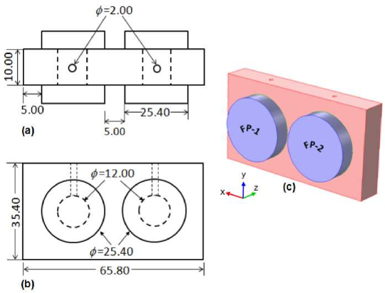
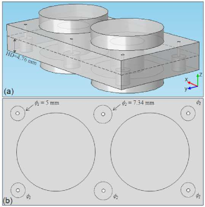
The main component of the proposed device is a two-channel FP etalon. It consists of two cylindrical cavities of diameter 12 mm each, bored adjacent to each other on a rectangular block ( mm3) of ultra low expansion (ULE) glass. The cavity mirrors are made of fused silica (FS) and optically contacted on either side of the spacer block. We assume the optical contacts to be sufficiently strong and free from any imperfections. This is a reasonable assumption as the modern techniques of joining optical elements have become more robust Haisma et al. (2007). A CAD geometry of the device is shown in Fig. 1. The low-finesse astro-cavity (FP1) is to provide astronomy calibration lines and high-finesse lock-cavity (FP2) is to provide a light channel for robust laser-lock. The cavity length =1 cm is chosen to produce 15 GHz apart reference lines to calibrate a typical high resolution (100,000) Echelle spectrographs. To maintain sufficient rigidity of the entire structure, a small 5 mm gap is provided on all sides between mirrors and spacer edges. Cavity mirrors are assumed to be flat. Replacing flat mirrors with curved mirrors will not alter our analysis in any major way, except a very small change in curvature due to differential thermal expansion.
2.2 Laser-lock and Drift Tracking Mechanism
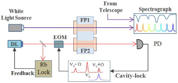
The conceptual principle of dual FP cavity-lock is illustrated in Fig. 2. The cavity drift can be tracked in several ways, but often requires two lasers Riehle (1998). However, the same goal can be accomplished using a simpler approach of sideband locking which needs only one laser Thorpe et al. (2008); Livas et al. (2009). In this method the frequency of the laser is pre-stabilized to Rb-cell using standard saturation absorption Wieman & Hollberg (1991). A tunable electro-optic modulator (EOM) creates radio frequency (RF) sidebands around the central frequency of the laser. One of the sidebands is then locked to the nearest resonance peak of FP2 cavity using modified Pound-Drever-Hall (PDH) method. The RF frequency of the oscillator driving EOM is servo-locked to cavity. This technique preserves the intrinsic stability of main laser beam that is locked to rubidium while exploiting the sideband tunability to track the cavity drift.
To estimate the drift, the frequency of the radio oscillator has to be readout independently by a frequency counter or RF spectrum analyzer. A fractional length change () about of the cavity block corresponds to RV error of 10 cms-1 or a RF frequency shift of few Hz in an EOM operating at 1 GHz. Measuring a GHz RF signal with an accuracy of few Hz (amounting to few ppb frequency resolution) is a challenging task. However, the desired precision can be reached with many cycles of repeated measurements. Alternatively, optical-beat measurement with two lasers yields much better sensitivity when the cavity is used in reflection mode, i.e. PDH locking Reiners et al. (2014); Davis et al. (2007). For example, a fractional change of the cavity length would induce a readily measurable frequency excursion of kHz in the optical-beat signal obtained with PDH setup using 780 nm laser. The exact implementation details will be worked out in a separate study.
3 Cavity Deformation
The resonance stability of FP cavity is determined by the stability of optical length between each mirror pairs. Different noise sources e.g., seismic and acoustic vibrations, material inhomogeneities, fluctuations in temperature, pressure and refractive index of the air etc influence the cavity stability. The impact of pressure on refractive index fluctuations is largely eliminated by placing the cavity inside a vacuum tank. A properly designed vacuum system also attenuates acoustic noise. Our focus in this study is on temperature and vibration perturbations which affect the long- and short-term stability of the Fabry-Perot cavity. To achieve a desired tracking accuracy the length changes in astro-cavity FP1 must strongly correlate with the length changes in lock-cavity FP2. How well and correlate would largely depends on cavity geometry and the way noise is transmitted into the experiment. Normally, the thermal and acoustic noise couples into cavity through mounting and support system. The main purpose of this paper is to estimate noise levels for which the differential length change in two cavities, becomes significant. In other words, when , the change in RF lock-point of FP2 would accurately reflect the length changes in FP1. Uncorrelated cavity deformations would render the laser-lock technique ineffective.
The shape of an elastic body can deform under the application of a force that may arise from constant acceleration (e.g. gravity loading), floor-vibrations, shocks or acoustic pickup. In most cases, acceleration experienced by a cavity is in the form of vibration perturbations. These perturbations are time-dependent and contain a large range of frequencies that excite various mechanical eigenmodes of the cavity. The exact nature of interaction depends on wavelength of excitation relative to the physical size of the cavity Nazarova et al. (2006). In high-frequency limit (small wavelength), a full dynamic analysis is needed to obtain a complete information of local strain and displacement of the cavity points. Since the excitation wavelengths at higher frequencies are significantly smaller than the cavity size, the conventional numerical discretization methods for dynamic analysis are inefficient and require significant computer resources. Though from practical viewpoint, the high frequency vibrations are less of a problem. They can be effectively attenuated in lab using vibration isolation tables, suitable damping materials, soft cushioning and multi-stage suspension.
In low-frequency limit ( Hz) the dynamic problem of cavity deformation can be reduced to static analysis Chen et al. (2006). In this regime the excitation wavelength become longer than the cavity size and all points in the cavity respond to the applied force in unison manner. The low-frequency collective motions (compression or stretching) of the particles can be approximated by quasi-static equilibrium resulting from application of a static force or a constant acceleration. Traditionally, the vibration or acceleration sensitivity of a cavity is expressed in normalized units of acceleration due to gravity [ms-2]. In this work we also follow the same convention.
3.1 Mathematical formulism
Elastic solids change shape under the influence of external force. The elastic deformations can be quantified by knowing the displacement of material points inside the body. Mathematically, elasticity problem can be formulated in terms of field equations which govern the relations among displacements, strains and stresses inside a loaded object. The basic field equations for linear isotropic solids comprise Sadd (2009):
-
Strain-displacement relation (compatibility equations)
(1) which completely specifies the strain in terms of displacement and its derivatives.
-
Equations of equilibrium
(2) which is a statement of Newton’s 2nd law for static cases where displacement has no time dependence and derivatives of stress tensor and body forces add to zero.
-
Constitutive equations (Hooke’s Law)
(3) which establishes general stress-strain behaviour via material parameters, i.e., Young’s modulus and Poisson’s ratio .
But for simple geometries, the solution of general system of Eqs.(1)-(3) by analytical methods is almost impossible. Sometimes further simplifications are made by developing a reduced set of field equations solely in terms of stresses or displacements. One such formulism is to eliminate stresses and strains from Eqs.(1)-(3) and express the displacement in a simplified form, known as Navier’s equation. The vector form of Navier’s equation is Sadd (2009):
| (4) |
where is shear modulus and is Lamé’s constant. Equation (4) is usually solved with displacement boundary conditions of the form: , where denotes the boundary points on the surface of the body and are prescribed displacement values.
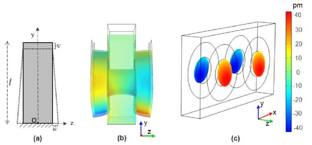
As a rough approximation, the cavity deformation problem is similar to stretching or compression of a prismatic bar when acted upon by an external force. For illustration, we consider a simple rectangular block of length resting horizontally as shown in Fig. 3(a). Such a block will be compressed by its own weight with body forces and , where is the mass density and is acceleration due to gravity. This problem can be solved by direct integration of field equations. To prevent the translation of the bar we fix the central point at the lower end of the bar, that is, and . Further, the rotation of the bar about and about an axis parallel to is prevented by setting at point . Final expressions for three displacement components can be written as:
| (5) | |||||
| (6) | |||||
| (7) |
where is the material density, is the acceleration, is Poisson’s ratio, is dimension of the bar along the direction of the force. From Eqs.(5)-(7) and Fig. 3(a) we note that points on the y-axis are only vertically compressed, i.e., . For other points on the bar, the vertical contraction is accompanied by a finite stretching and in other two orthogonal directions. The coupling of the displacement field is mediated by non-zero value of Poisson’s ratio.
3.2 FEA Simulations
The example of a prismatic bar illustrated in previous section has an analytical solution due to simple geometry. The actual structure of the FP is quite complex. It has two large cavities and four mirrors attached to the spacer. The dimensions as well as mass of the mirrors are also comparable to the spacer. Using analytical means to find a closed-form solution for complicated geometry is extremely difficult task. We, therefore, used finite element analysis (FEA) to solve our 3D problem numerically. The FEA is by far the most widely used and versatile numerical technique for simulating deformable solids.
We chose COMSOL Multiphysics 111COMSOL Multiphysics Pvt. Ltd., http://www.comsol.com/ as our FEA simulation software. It provides a complete and integrated environment for creating, analyzing and visualizing multiphysics models. Built-in CAD tools and the Structural Mechanics module was used for constructing a 3D model of the FP cavity. Additional quantities and model inputs (e.g. boundary constraints, body load, material type and properties etc.) for stress and displacement analysis were defined in Solid Mechanics interfaces of the Structural module. The relevant material properties used in this study are listed in Table 1. The mesh settings determine the resolution of the mesh element used for discretizing the model. In all simulations we used default tetrahedral mesh shape. Extra-fine mesh size was chosen to minimize the discretization error. For our study, we selected the stationary solver since our load, stress and deformation do not vary with time. The Solid Mechanics kernel numerically solves the Navier’s equations (Eqs.(4)) and computes displacements, stresses, and strains over the entire FP domain. The deformation of a material point () in FP geometry is quantified by calculating the displacement () from the undistorted shape. In subsequence analysis, our prime interest will be in displacement component which is along the axis of the cavity, i.e. -direction.
| Property | Material | Units | ||
| ULE | Silica | Zerodur | ||
| Density () | 2.21 | 2.20 | 2.53 | kgm-3 |
| Young’s modulus () | 67.6 | 73.1 | 90.3 | Pa |
| Poisson’s ratio () | 0.17 | 0.17 | 0.24 | – |
| CTE () | 0.03 | 0.55 | -0.08 | |
| Thermal conductivity () | 1.13 | 1.38 | 1.46 | |
| Heat capacity () | 767 | 703 | 821 | |
4 Horizontal Mounting
The FP is mounted horizontally in -plane as shown in Fig. 1. The cavity axis is along -direction. Since the cavity length is short we have not considered any discrete support for horizontal mounting. Instead we let the spacer block rest on the bottom plane.
4.1 Deformation due to uniform gravity load
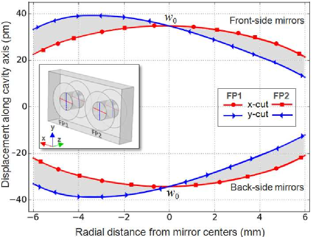
First we investigate a simple case where the FP unit is deformed under its own weight, i.e., force of gravity acting uniformly on entire geometry in direction. Fixed boundary constrain is imposed on the bottom -plane of the spacer to prevent rigid body motion in FEA simulations. Cavity deformation in -plane due to gravity load is illustrated in Fig. 3(b). In accordance with Eqs. (3)-(5), the gravity-induced compression of the cavity in vertical direction also causes it to expand in -direction, thus increasing the mirror separation. In order to numerically compute the cavity length changes, we extract the displacement component for each mirror surface that is bonded to the spacer block. The numerical probe points are defined along and -direction (see the Fig. 4 inset) on the interior surface of the mirrors forming cavities. The numerical displacement of the probe points, namely the -cut and -cut, is shown in Fig. 4. In simulations the origin of the coordinate system was chosen to coincides with the geometrical center of the FP spacer block. A near overlap between the FP1 and FP2 probe points indicate that both cavities are deformed identically under the force of gravity.
It is also evident from Fig. 4 that displacement is not uniform across the cavity cross-section. The horizonal bulge shown by concave shaped red curves, is symmetric about the mirror centers where the displacement is maximum ( m) and reduces to about m towards to cavity edge. The displacement of the vertical probes, i.e., the -cut shown in blue, is asymmetric. It is minimum ( m) at the cavity top edge, attains maxima ( m) at about 3 mm below the mirror centers and reduces slightly towards the edges. This asymmetry in displacement is because of the unequal weight along vertical direction and a small -tilt caused by outward buckling of the spacer and the mirrors. The -displacement of any other point on the mirror surface is bound by gray area between the blue and red curve.
Since the displacement is not uniform across the reflecting face of the mirror we express the effective cavity length change for each cavity as the difference in displacement of the mirror centers. Finally, the quantity of interest for us is differential length change between two FP cavities, i.e. . For the present case, we find pm and . This is expected as the applied gravity load is symmetric and both cavities are deformed equally.
4.2 Orientation Dependent Noise in Horizontal Mounting
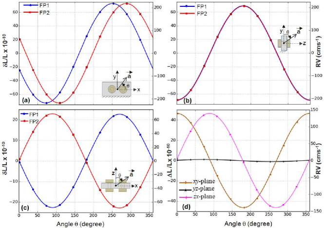
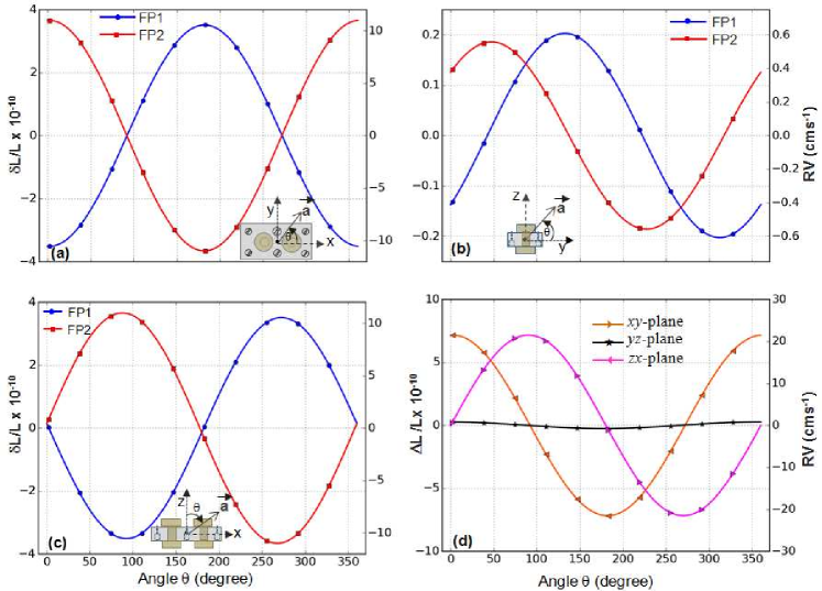
Now we examine cavity’s response to a gravity-like static force that is orientation dependent. This exercise is aimed at understanding the relative sensitivity of the FP to direction dependent noise perturbations. In simulations, we swept the acceleration vector in different planes and computed differential length change for each orientation. The acceleration oriented in a given -plane, can be expressed in its components along and directions, i.e., , where for consistency we have chosen . Using parameter sweep feature of the COMSOL we simulated the impact of different orientation of in the -plane. Cavity length change and as a function of orientation in different planes is shown in Fig. 5. The impact of orientation dependent force can be understood by analyzing its response on cavity length separately along each direction. A few noteworthy observations are:
-
•
When the acceleration is along the -direction ([] in Fig. 5(a) and [] in Fig. 5(c)) the sheared strain in FP is produced in such a way that FP1 cavity mirrors are deflected inward [outward] and FP2 cavity mirrors are deflected outward [inward]. Such response can be attributed to unequal shear strain produced because of the constrained boundary and geometrical asymmetry of the cavity in -direction. A significant differential length change (pm) occurs due to shortening of one cavity and elongation of the other. This amounts to spurious RV tracking errors about 140 cms-1 or equivalently a frequency shift of 1.8 MHz at 782 nm laser.
-
•
Horizontally mounted dual FP is largely immune to relative length change in vertical vibrations. When the acceleration is oriented in -direction ([] in Fig. 5(a) and [] in Fig. 5(b)) it imparts equal length changes ( pm) to each cavity. Since both cavities respond in same way, the relative length change between two cavities is nearly zero. Therefore, a tracking mechanism would measure a correct drift caused by vertical acceleration.
-
•
When the acceleration is in -direction ([] in Fig. 5(b) and [] in Fig. 5(c)) each mirror is displaced along the cavity axis by same amount without causing any relative drift i.e., .
v
From the proceeding analysis we conclude that proposed FP device is immune to differential length changes if the acceleration noise is oriented along the cavity length and in the vertical direction. However, the noise coupling in -direction can induced non-zero differential length changes () between two cavities. In such case, the instantaneous drift measured by laser-lock setup will not be same as the drift of astro-cavity. Based on the type of noise some strategies can be adopted to overcome this limitation. For example, a typical noise spikes (an impulse excitation) only lasts for a fraction of second and temporarily deforms the elastic cavity to produce uncorrelated tracking error in drift measurement. After the noise pulse has elapsed the elastic cavity would return to its original shape and laser-lock would resume the correct measurements. In such case, the actual drift has to be estimated from a series of measurements by carefully discarding the erroneous data. If the source of noise is constant then setup has to be properly shielded. For example, the measurement error due to differential length changes in the proposed device can be reduced below cms-1 level by attenuating the noise by .
5 Vertical Mounting
The vibration sensitivity of a cavity can be greatly reduced by mounting it vertically. In this scheme the cavity axis is aligned along gravity and FP is held close to the spacer mid-plane as illustrated in Fig. 6. The major advantage of this configuration comes from symmetric distribution of mass above and below the cavity mid-plane. The top and the bottom mirrors are equally displaced by force of gravity in downward direction thus resulting in near-zero change in cavity length. A mounting mechanism can be devised to hold the cavity at suitable supporting positions -also called Airy-points. The cavity spacing can be made invariant by optimizing the size, location and depth of the supporting points.
Three pairs of mounting holes are partially drilled to provide discrete support-points at the under-side of the rectangular spacer. These holes are drilled up to the cavity mid-plane as shown in Fig. 6(a). The flat bottomed-surface of each hole provides a smooth contact area for cavity to rest on mounting posts from below. Alternatively, the FP can be hanged in air by using suspension wires from the above. The retaining disks attached to each end of the wire and smoothly inserted into the mounting holes will wear the cavity weight uniformly. The concentric through-holes (dia 1 mm) are only shown to provide necessary clearance for wires. The diameter of the mounting holes at the corners (, see Fig. 6(b)) is chosen to be 5 mm to maintain a sufficient wall thickness from edges.
Optimization of Airy-points
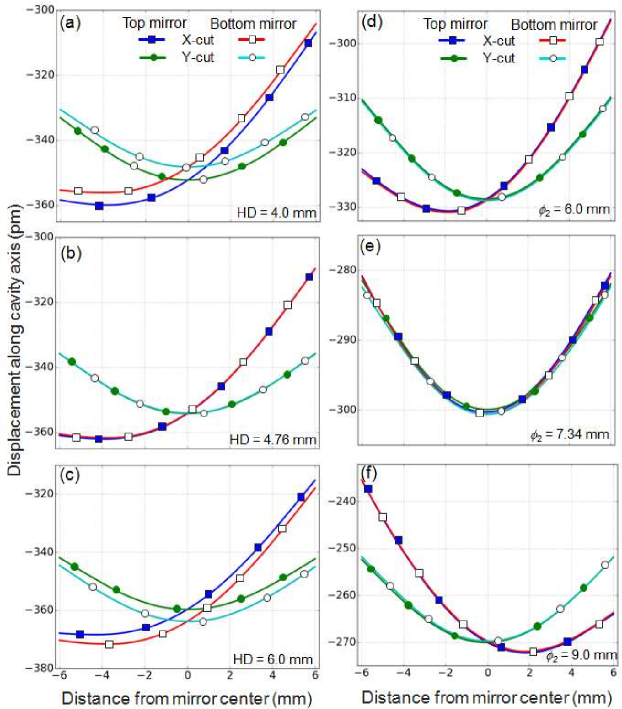
In vertical mounting Airy-points are not located exactly at the geometric mid-plane of the cavity. This is because the compression in upper-half of the cavity is not exactly countered by stretching in lower-half. In addition there is a weight imbalance around the supporting points. The material removed to form mounting holes reduces the weight of the lower-half of the spacer block. In order to correctly locate vertical position of the Airy points, we first varied the mounting hole depth (HD) in our simulations and determined the gravity induced displacement of top and bottom mirrors. The cavity length change is inferred from the displacement of probe points located on the inner surfaces of mirrors as discussed in previous Section.
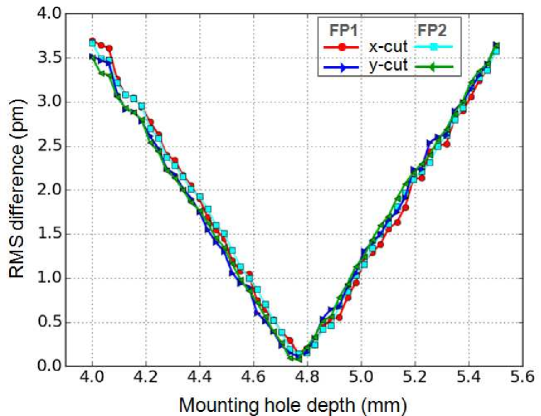
Three test cases with different displacement trends are shown in Fig. 7(a)-(c). When the supporting surface is below the cavity-mid plane, e.g. HD = 4 mm in Fig. 7(a), the vertical displacement of the upper mirrors is higher as seen from corresponding - and -cuts. The situation is reversed in Fig. 7(c) where the supporting location HD = 6 mm was moved above the cavity-mid plane. The null point occurred at HD = 4.76 mm in Fig. 7(b) for which the displacement of top and bottom mirrors become nearly equal and the cavity length becomes invariant. Figure 8 shows the rms separation between the top and the bottom cavity mirrors at various hole depths. The fractional length change at optimal hole-depth for both cavities is below . If we assume manufacturing tolerance of m, the rms difference still remains below pm, indicating the robustness of the design against machining errors. This tolerance limit is well within the current technology of precision manufacturing.
Shape of the profile along - and -directions in Fig. 7(a)-(c) also indicates that displacement is not uniform across the cavity cross-section. A linear -tilt is added onto a radially symmetric sag. This tilt is caused by bending of spacer in the middle that bears larger mass concentration. We enlarged the diameter to remove extra material for balancing and equalizing the weight distribution in middle part of the spacer. Figure 7(e)-(f) demonstrates how the tilt component (x-cut) changes sign when was varied from 6 mm to 9 mm. At optimum diameter ( mm in Fig. 7 (e)), the tilt component was largely eliminated and the rms difference between and -radial profile was reduced below m.
Having found an equilibrium plane for support, we also estimated the direction dependent noise sensitivity of the vertical mount. For FEA simulations, the mechanical displacement of the mounting holes was constrained and the FP geometry was subjected to a sweeping acceleration vector in different planes. The calculated cavity length variations and differential length change is plotted in Fig. 9. For acceleration along , the vibration sensitivity to differential length change has reduced by a factor of seven compared to horizontally mounted case. For acceleration along and -direction, the RV error is below 1 cms-1g-1. Since the vibration sensitivity is significantly reduced in vertical mounting scheme, the requirements for external noise isolation and damping are also relaxed.
6 Temperature Sensitivity
Thermally induced material expansion or contraction is also a major source of noise against the dimensional stability of optical materials. A desired length stability of FP cavity can be assured by choosing appropriate spacer/mirror material with low thermal expansion coefficients. To minimize the impact of temperature fluctuations, the reference cavities are also operated near their zero-crossing temperature Legero et al. (2010). The entire setup is enclosed inside an evacuated and thermally shielded environment. In this section we investigate effect of temperature fluctuations on our FP cavities. To first approximation, the cavity length changes in FP1 and FP2 will strongly correlate if temperature variations within the enclosure are uniform. In that case the tracking mechanism would expectedly register a correct drift. However, small temperature gradients inside the enclosure will expose two cavities to a locally different environment, producing dissimilar length changes in FP1 and FP2. This would contaminate the tracking signal with intractable radial velocity errors.
6.1 Effect of Temperature Gradients
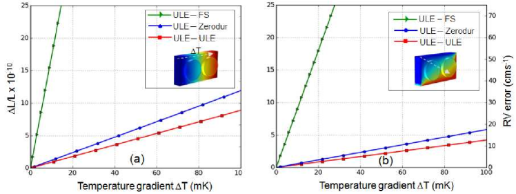
To analyze the temperature sensitivity of the FP we again used FEA to solved the thermal-stress problem with COMSOL multiphysics. In our thermal model, realistic temperature gradients were simulated by imposing appropriate temperature conditions on selected boundaries of the spacer block. A steady-state numerical solution then establishes a linearly varying temperature and stress fields between the selected sides. Temperature sensitivity also depends on the choice of the spacer and mirror material. In these studies, Corning ULE was used as cavity spacer while three glass-ceramics namely, Zerodur, Silica and Corning ULE were tested for mirror substrates. Two worse case scenario producing unequal cavity length changes are shown in Fig. 10. The temperature sensitivities ( per mK) of the device can be determined from the slopes of the plots. Among the chosen spacer-mirror pairs, the ULE-FS cavity has the largest sensitivity mK -1 (RV error 3.81 cms -1 mK -1) while ULE-ULE has the least sensitivity mK -1 (RV error 0.27 cms-1mK-1) for temperature gradient shown along spacer edge in Fig. 10(a). As see in Fig. 10(b), the temperature sensitivity is almost halved for the gradient considered along diagonal direction.
The contribution of CTE to cavity length change from mirror substrate is substantially large compared to the contribution from spacer material. The main drawback of fused silica is its large CTE which places stringent requirements on the design of thermal control system of the cavity. For example, to keep the RV error of dual cavity FP below 1 cms-1 level, a temperature uniformity at sub-mK level has to be ensured. This requirement is relaxed to few-mK if both spacer-mirror pair are made with extremely low expansion materials such as Zerodur and ULE. A new method of building temperature insensitive FS cavity mirrors is expected improve their performance in precision metrology Legero et al. (2010). Despite large CTE, fused silica is considered as best performing material for cavity mirrors. This is because FS has very small mechanical losses at room temperature which helps to lower cavity’s thermal noise floor which is about 2-3 times better compared to the ULE or Zerodur Numata et al. (2004).
6.2 Effect of Temperature on Unequal Cavity Spacing
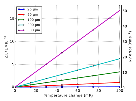
In ideal case of equal length cavities i.e , temperature fluctuations will not produce any relative length change between two cavities. In practice, it is not possible to manufacture cavities of equal length with arbitrary precision. A small offset in lengths may arise from machining errors and/or imperfections in the optical bonding between the mirrors and the spacer. To study this effect we created cavities with different length offset and calculated their differential expansion from the thermal model. The length offset was introduced by shortening the spacer thickness of FP1 without altering . In the FEA simulations the temperature of the entire FP block was varied uniformly in step of 1 mK. Figure 11 shows thermally induced differential length changes between two cavities for different length offsets. Clearly, a 0.1 K difference from the temperature set point can produce pm differential expansion (the green curve in Fig. 11) between two cavities if the initial length offset was m. This amounts to cms-1 RV tracking error. These calculations reinforces the need of high thermal stability (few mK) and cavity length matching better than m for keeping the influence of temperature changes on RV error below 1 cms-1.
7 Numerical Accuracy
In FEA, the numerical solution of a problem is approximated by partitioning the CAD geometry into smaller parts. The accuracy of the numerical solution is intrinsically linked to the mesh size. By refining the mesh, the solution becomes more accurate but this is achieved at the cost of finite computational resources and time. In a realistic FEA model, the difference between exact and approximate solution should be minimized and error should not exceed the tolerance limit defined by some accepted criteria.
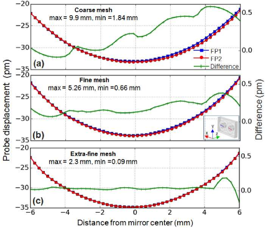
We used the default tetrahedral mesh settings with adaptive mesh refinement in our FEA software to discretize the cavity model. The refinement algorithm globally adjusts the mesh size to provide sufficient resolution around all regions of interest within the geometry. There is no generic rule to verify the numerical accuracy of FEA model -especially in complex problems where exact solution is not known a priory. In order to evaluate the discretization error due to finite mesh size, we compare the relative displacement of FP1 and FP2 mirrors for a simple gravity loading case (see Fig. 4) already discussed in Section 4.1. From the application of uniform load and symmetry consideration, exact solution requires the cavity displacement in FP1 and FP2 to be equal. Any difference in displacement can be attributed to numerical inaccuracies originating from meshing errors. Figure 12 shows the displacement data (-cut) plotted for input cavity mirrors at three different mesh densities.
We note that compared to the smaller mesh sizes, the magnitude of the displacement is slightly underestimated at ‘coarse mesh’. In addition, a small relative difference can also be seen in Fig. 12(a). This difference reduces progressively with decreasing mesh size (see Fig. 12(b)) and becomes insignificant for ‘extra-fine mesh’ shown in Fig.12(c) where two curves completely overlap. In each case the numerical error is estimated from the rms difference between the two curves. The discretization rms error for extra-fine mesh is m. This amounts to error for cavity length stability targeted at m level. All FEA simulations in this paper were carried out with extra-fine mesh.
Another possible source of error is uncertainties in thermal and mechanical properties of the ceramic material listed in Table 1. Typically, the material parameters can have about deviation from their nominal values. We varied the material parameters in our simulation by but did not find any noticeable difference in vibration or temperature sensitivities. The calculated deviation was of the same order as the discretization errors. This is not unexpected since our FP is lightweight and cavity length is short. For the same level of uncertainties in Poisson ratio, Youngs modulus and material density, a vibration sensitivity of was achieved in longer cavities Nazarova et al. (2006).
8 Summary
The Doppler survey for many astronomy programmes requires high resolution spectrograph with exceptional long term stability in RV precision. In this paper we have proposed a double cavity FP design for aiding high precision Doppler measurements in astronomy. The proposed device has two parallel optical cavities embedded inside a 10 mm thick monolithic ULE block. A low-finesse astro-cavity is meant to generate multiline reference spectra for spectrograph calibration while a high finesse lock-cavity is needed to provide steep discriminant signal for tracking the cavity drift. External noise can have severe detrimental effect on the performance and reliability of the tracking measurements. An accurate measurement of drift is possible only if the noise interventions are common to both cavities.
We have used FEA to analyze FP’s sensitivity to mechanical vibrations and temperature fluctuations. A 3D FEA simulations were carried out for the FP structures comprising five domains (4 mirrors + 1 spacer). An optimized cavity design with proper mounting and support system helps insulate the noise. Two mounting geometries were investigated for tracking errors resulting from differential length changes between the cavities. The horizontal geometry showed vibrational sensitivity up to (RV errors cms-1) for acceleration directed along the longer edge (-axis) of the block. The noise along - and -direction is common and does not contribute to differential length change. For achieving 1 cms-1 RV stability of the device the horizontal mounting configuration may require a well thought strategy to insulate the vibration noise down to .
Cavity lengths can be made invariant by mounting the FP vertically. We worked out a vibration insensitive design by numerically optimizing the hole-depth and diameter of the mounting holes. In the optimized design the tilt-component was eliminated and a clear null point was achieved for gravity induced displacement between the mirrors.
We also studied the impact of thermal instability and choice of mirror/spacer material on the tracking performance. A steady-state thermal analysis was carried out to evaluate the effects of thermal gradient. Numerical simulations show that temperature gradient within the FP enclosure has to be accurately controlled and relative length offset between two cavities should be minimized to avoid differential length changes that may cause spurious drift and unintended tracking errors. The proposed dual FP device can be easily fabricated with available machining precision of m and readily achievable thermal stability of few mK.
This work is also relevant to cavities used in laboratory experiments designed to test Lorentz invariance where a pair of orthogonal FP cavities is employed to detect anisotropy in the speed of light Herrmann et al. (2010). The entire optical setup is put on a rotating table. A frequencies beat-note between two lasers, each locked to one of the two orthogonal cavities, is examined while the entire setup is continuously rotated on the turntable. Any possible anisotropy is expected to modulate the laser beat signal at twice the rotation rate. However, the discrimination of the anisotropic signal from competing noise artifacts is not trivial. Even though the length of two cavities is defined by a single ULE block, detection ambiguities may arise, e.g., from periodic deformation of cavity length caused by gravitational and centrifugal forces. The approach outlined in our studies might be useful to understand and model various systematics producing relative drift in cross-cavities.
Acknowledgement
RKB acknowledges the research support for this project (reference no. EMR/2014/000941) from Science and Engineering Research Board (SERB), Department of Science and Technology (DST), INDIA. A.R. acknowledges the research support from European Research Council under the FP7 Starting Grant agreement number 279347 and funding from DFG grant RE 1664/9-1.
References
- Abbort et al. (2016) Abbott, B. P., Abbott, R., Abbott, T. D. et al. [2016] Phys. Rev. Lett. 116, 061102.
- Anglada-Escudé at al. (2016) Anglada-Escudé, G., Amado, P. J., Barnes, J. et al. [2016] Nature 536, 437.
- Argence et al. (2012) Argence, B., Prevost, E., Lévèque, T. et al. [2012] Opt. Express 20, 25409-25420.
- Black (2001) Black, E. D. [2001] Am. J. Phys. 69, 79-87.
- Chen et al. (2006) Chen, L., Hall, J. L., Ye. J. et al. [2006] Phys. Rev. A 74, 053801.
- Davis et al. (2007) Davis, M. J., Hayden, J. S. & Farber, D. [2007] “High Precision Thermal Expansion Measuremnts Using Small Fabry-Perot Etalon,” in it Proc. SPIE, Time and Frequency Metrology 6673, 66730R.
- Denus-Baillargeon et al. (2014) Denus-Baillargeon, M. M., Schmitt, T., Larouche, S. & Martinu, L. [2014] Appl. Opt. 53, 2616–2624.
- Drever et al. (1983) Drever, R. W. P., Hall, J. L. Kowalski, F. V. et al. [1983] Appl. Phys. B 31, 97–105.
- Fischer et al. (2014) Fischer, D. A., Howard, A. W., Laughlin, G. P. et al. [2014], “Exoplanet detection techniques,” in Protostars and Planets VI, pp. 715-737.
- Fisher et al. (2016) Fischer, D. A., Anglada-Escude, G., Arriagada P., Baluev R. V. et al. [2016] Pub. Astron. Soc. Pac. 128, 066001.
- Florian et al. (2015) Florian B. F., Zechmeister, M., & Reiners, A. [2015] A A 581 A117 (2015).
- Fox (2009) Fox, R. W. Opt. Express 17, 15023–15031.
- Gábor et al. (2014) Gábor, F., Glenday, A. and Latham, C. [2014] “An economic Fabry-Perot wavelength reference”, in SPIE Astronomical Telescopes & Instrumentation, pp. 915156-915156.
- Haisma et al. (2007) Haisma, J., Hattu, N. Pulles, J. T. C. M. et al. Appl. Opt. 46, 6793-6803.
- Halverson et al. (2014) Halverson, S., Mahadevan, S., Ramsey, L. et al. [2014] Pub. Astron. Soc. Pac. 126, pp. 445-458.
- Herrmann et al. (2010) Herrmann, S., , Senger, A., Möhle, K. et al. [2010] Phys. Rev. D 80, 105011.
- Huke et al. (2015) Huke, P., Holzhuter, H.,& Reiners, A. [2015] “Transfering Rb+ hyperfine-structure stability to a Fabry-Perot resonator used as a frequency standard for astronomical spectrographs,” in Proc. SPIE 9526,98260I-7.
- Julian et al. (2016) Julian, S., Seifahrt, A., Schwab, C., & Bean, J. L. [2016] arXiv: 1607.05172 (2016).
- Jun & Lynn (2003) Jun, Y. & Lynn, T.W. [2003] Adv. At. Mol. Opt. Phy. 49, 1-83.
- Kim et al. (2009) Kim, G., Whitmore, J. B., Wolfe A. M. et al. [2009]ApJ 708, 158.
- Legero et al. (2010) Legero, T., Kessler, T. & Sterr, U. [2010] J. Opt. Soc. Am. A 27, 914-919.
- Livas et al. (2009) Livas, J. C., Thorpe, J. I., Numata, K. et al [2009] Classical Quant. Grav. 26, 094016.
- Marcy & Howard (2011) Marcy, G. & Howard, A. [2011] “The astrophysics of planetary systems: formation, structure, and dynamical evolution,” in Proc. IAU Symposium, pp 3–12.
- Murphy et al. (2007) Murphy, M. T., Udem, T., Holzwarth, R., Sizmann, A. et al. [2007] MNRAS 380, 839-847.
- Nazarova et al. (2006) Nazarova, T., Riehle, F. & Sterr, U. [2006] Appl. Phy. B 83, 531-536.
- Numata et al. (2004) Numata, K., Kemery, A. & Camp, J. [2004] Phys. Rev. Lett. 93, 250602.
- Pepe et al. (2014) Pepe, F., Ehrenreich, D., & Meyer, M. R. [2014] Nature 513, 358-366.
- Probst et al. (2014) Probst, R. A., Lo Curto, G., Avila, G., et al. [2014] “A laser frequency comb featuring sub-cm/s precision for routine operation on HARPS,” in SPIE Astronomical Telescopes & Instrumentation, pp. 91471C-91471C.
- Quinlan et al. (2010) Quinlan, F., Ycas G., Osterman S., & Scott A. D. Rev. Sci. Instrum. 81, 063105.
- Reiners et al. (2014) Reiners, A., Banyal, R. K. & Ulbrich, R. G. [2014] A&A 569, A77.
- Riehle (1998) F. Riehle, [1998]Meas. Sci. Technol. 9, 1042–1048.
- Sadd (2009) Sadd, M. H. [2009] “Elasticity: theory, applications and numerics” (Academic Press).
- Santos et al. (2006) Santos, N. C., Pasquini, L., Correia, A. C. M. & Romaniello, M. [2006] “Precision Spectroscopy in Astrophysics,” in Proc. ESO/Lisbon/Aveiro Conference held in Aveiro, Portugal, pp. 63-215.
- Schäfer & Reiners (2012) Schäfer, S., & Reiners, A. [2012] “Two Fabry-Perot interferometers for high precision wavelength calibration in the near-infrared,” in SPIE Astronomical Telescopes & Instrumentation, pp. 844694-844694.
- Schwab et al. (20015) Schwab, C., Julian, S., Gurevich, Y. V. et al. [2015] Pub. Astron. Soc. Pac. 127, 880–889.
- Steinmetz et al. (2008) Steinmetz, T., Wilken, T., Araujo-Hauck, C. R. Holzwarth, et al. [2008] Science 321, 1335-1337.
- Thorpe et al. (2008) Thorpe, J. I., Numata, K., & Livas, J. [2008] Opt. Express 16, 15980-15990.
- Ujan (2011) Uzan, J. P. [2011] Living Rev. Relativity 14, 2.
- Vaughan (1989) Vaughan, M.[1989] “The Fabry-Perot interferometer: history, theory, practice and applications” (CRC press).
- Wildi et al. (2012) Wildi, F., Chazelas, B. & Pepe, F. [2012] “A passive, cost effective solution for the high accuracy wavelength calibration of radial velocity spectrographs,” in Proc. SPIE 8446, 84468E.
- Wieman & Hollberg (1991) Wieman, C. E. & Hollberg, L. [1991] Rev. Sci. Instrum. 62, 1-20.
- Ycas et al. (2012) Ycas, G. G., Quinlan F., Diddams S. A. et al. Opt. Exp. 20, 6631-6643.