Plasma Wave Seed for Raman Amplifiers
Abstract
It is proposed to replace the traditional counterpropagating laser seed in backward Raman amplifiers with a plasma wave seed. In the linear regime, namely, for a constant pump amplitude, a plasma wave seed may be found by construction that strictly produces the same output pulse as does a counterpropagating laser seed. In the nonlinear regime, or pump-depletion regime, the plasma-wave-initiated output pulse can be shown numerically to approach the same self-similar attractor solution for the corresponding laser seed. In addition, chirping the plasma wave wavelength can produce the same beneficial effects as chirping the seed wave frequency. This methodology is attractive because it avoids issues in preparing and synchronizing a frequency-shifted laser seed.
pacs:
52.35.Mw, 52.59.Ye, 42.65.YjTo overcome the thermal damage limit of conventional materials Strickland and Mourou (1985); Dubietis et al. (1992), it has been proposed to employ plasma to mediate intense laser amplification Shvets et al. (1998); Malkin et al. (1999). Different backscattering coupling techniques were then explored, including Compton scattering Shvets et al. (1998); Dreher et al. (2004), resonant Raman scattering Malkin et al. (1999); Ping et al. (2004); Cheng et al. (2005); Ren et al. (2008); *ExpNat2007-Suckewer; Yampolsky and Fisch (2011); Pai et al. (2008); Ping et al. (2009); Lehmann and Spatschek (2014), Brillouin scattering Andreev et al. (2006); Lancia et al. (2010); Weber et al. (2013); Lancia et al. (2016); Edwards et al. (2016), magnetized scattering Shi et al. (2017), and chirped pump Raman amplification Ersfeld and Jaroszynski (2005). In a Raman amplifier, a long pump laser pulse deposits its energy to a counterpropagating short amplified pulse, mediated by a plasma wave. The amplified pulse duration contracts while its amplitude grows, thereby producing an ultraintense laser pulse. To initiate the amplification, the amplified pulse is seeded by a short laser seed, down-shifted from the pump frequency by the plasma frequency, and synchronized to meet the pump as the pump leaves the plasma. Preparing such a frequency-shifted, synchronized laser seed represents a significant technological challenge.
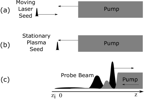
It has been proposed for strongly coupled Brillouin scattering to form a laser seed by reflection of the pump Peng et al. (2016). However, a simple reflection does not produce the frequency down-shift necessary for Raman resonance. It is proposed here instead to replace the laser seed with a plasma wave seed. The plasma wave has a negligible group velocity, so without regard for synchronization, the amplification process is triggered only when the pump wave reaches it. In Fig. 1, we compare seeding by a laser pulse (a) and by a plasma wave (b). For laser seeding, there exist solutions in which an intense counterpropagating wave is produced, with pump depletion (c), in which the counterpropagating pulse consumes essentially all the energy of the pump beam, while contracting in time Malkin et al. (1999). These solutions give rise to extreme intensities. However, there are other solutions, depending on how the laser seed is prepared with a front that is not steep enough, or with not enough initial energy content, in which these promising solutions do not obtain Tsidulko et al. (2002). The question to be answered here is whether one can construct with a plasma wave seed the same promising solutions that were constructed with a suitably constructed laser seed.
What is shown here is that, in fact, such solutions for the counterpropagating pulse, which we shall call the “probe pulse”, can be constructed for the plasma wave seed as well, and that they are attractor solutions. For nearly all laser-seeded interactions resulting in complete pump depletion, a plasma-wave-seeded interaction can be found to produce the same time-asymptotic output pulse. This reachable subset includes the advantageous output pulses depicted in Fig. 1(c). The key plasma parameters for efficient amplification Malkin and Fisch (2014) will remain the same. Moreover, we show that the advantages that accrue to laser seeding through frequency chirping Toroker et al. (2012) can be realized as well through plasma wave seeding with wavelength chirping.
To proceed, consider the three-wave resonant Raman coupling process Kruer (1988). For the case of the seeded plasma wave, an electron density ripple, , is produced with a wave vector . This ripple is produced in only a small localized region at the far end of the plasma, at the end where the pump wave exits. When encountered by the incident pump laser with a wave vector , electrons oscillate at velocity , and hence induce a transverse current, , with a wave vector , where is the elementary charge. If the wave vector and frequency of the transverse current are properly matched, a probe beam is generated. Importantly, for efficient Raman amplification, the dispersion relation determines the choice of such that , where is the pump frequency and is the plasma seed frequency. Here, and are the plasma frequency and the electron thermal velocity, respectively. For cold and underdense plasmas, ; hence, . Note that in the case of the laser seed, the frequency is red detuned from the pump frequency by . In contrast, the plasma wave seed should have the appropriate wavelength, and then the appropriately red-tuned frequency probe is automatically generated.
To develop an equivalence rule between laser and plasma seeds, we make the reasonable assumption that similar linear solutions (constant pump amplitude) will transition to the same nonlinear asymptotic attractor solutions which feature pump depletion. This assumption, of course, must be checked. However, the linearization allows us to rigorously construct a plasma wave seed with Green’s function response identical to that of a laser seed that has the desired wavefront sharpness and intensity.
Consider the configuration as illustrated in Fig. 1(b). At , the pump coming from the right edge meets the Langmuir wave at . We describe the envelopes of pump and probe lasers using the wave vector potentials and , normalized such that the pump intensity is , and similarly for , is the envelope of Langmuir wave normalized to , where for underdense plasmas (i.e., with being probe wave frequency) and linearly polarized optical beams. Without losing generality, we assume real and keep and complex. Here, is the electron mass, is the electrostatic field of the Langmuir wave, is the speed of light, and is the permittivity of free space. For simplicity, we neglect, at this stage, the group velocity dispersion (GVD), relativistic nonlinearity, and kinetic effects. The resonant three-wave equations in cold plasma can then be written as Malkin et al. (1999)
| (1) |
where the subscriptions and denote the partial time and derivatives, respectively.
In the linear stage, before the pump beam gets depleted (i.e., remains constant), the solution to Eqs. (1) can be obtained sup for , where
| (2) | ||||
| (3) |
are the components of the probe generated by a plasma seed and a laser seed , respectively, and
| (4) | ||||
| (5) |
are the Green’s functions associated with the corresponding seeds Shvets and Wurtele (1997). Here is the zeroth order modified Bessel function, is the Heaviside function, denotes the linear temporal growth rate, and .
In laser-seeded amplification, and . The probe beam comprises the initial laser seed [the second term in Eq. (5)] and the generated components from the three-wave process [the first term in Eq. (5)]. The generated component grows quasiexponentially and hence eventually dominates the probe. For a given laser seed , we now look for a plasma seed such that the resulting probe (in the linear regime) is the same, i.e., .
First, in analyzing the Green’s functions, note that
| (6) |
where the last term can be neglected at the wavefront . The identity (6) suggests taking the envelope of plasma wave seed to be
| (7) |
so that the generated probe beam can be found using integration by parts
| (8) |
Comparing Eqs. (3) and (Plasma Wave Seed for Raman Amplifiers) shows that the plasma wave seed, initiated according to Eq. (7), generates asymptotically a probe beam that has the identical wavefront which is generated by use of a laser seed.
As the probe pulse propagates and grows, if initially short enough, it should eventually deplete the pump and enter into the nonlinear or so-called “-pulse” regime, characterized by the self-similar contracting pulse envelope Malkin et al. (1999). The asymptotic equivalence expressed by Eq. (7) suggests that asymptotically identical pulses in the linear regime should evolve to identical pulses in the nonlinear regime. In the limit of short (delta function) laser seeds, and correspondingly short plasma seeds, a formal equivalence can be made sup . While the finite width case does not follow rigorously, we show numerically that the equivalence, in fact, does extend to finite pulse widths.
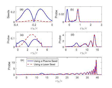
Thus, for finite width seeds, by numerically solving Eqs. (1), we compare amplification triggered by a plasma seed to that by a laser seed. As shown in Fig. 2(a), the laser seed envelope is Gaussian, with , with normalized width . Following the equivalence rule in Eq. (7), the plasma seed is taken as . The two peaks in differ by a phase difference of . In Fig. 2(b), we observe, at , that the probe beam generated by the plasma seed has a wavefront that exactly matches the laser seed. The identical wavefronts generated by different seeds ensure the same Raman amplification throughout , as shown in Figs. 2(b)-(e). They both reveal similar -pulse structures, with the amplitude in its leading peak increasing linearly and the pulse duration similarly contracting linearly in distance.
While we have constructed an envelope of the plasma seed that approaches the corresponding attractor solution of the laser seed, it is not necessarily a unique correspondence. Note that, while the laser seed has but one, the plasma seed in Fig. 2(a) has two maxima or two humps. However, the asymptotic solution clearly depends on only the first hump since the pump interaction with that hump will clearly shadow the second hump. Indeed, removing the second hump will give the identical asymptotic solution, which, in practice, makes easier the setting up of the plasma wave seed.
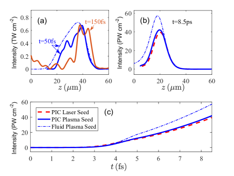
To examine kinetic effects using laser and plasma seeds, we conducted one-dimensional particle-in-cell (PIC) simulations (using the code EPOCH Arber et al. (2015)). For definiteness, we considered parameters similar to those of recent experiments Ping et al. (2009); Cheng et al. (2005). The electron density is and accordingly . The pump laser has wavelength and intensity . The linear growth rate is . Electrons are initialized to , which avoids Landau damping Sup . A cell size of is used to match the Debye length, with electrons per cell to reduce charge density fluctuations. Calculations are done in a window moving with the group velocity of the probe (). Collisions and ion motion are ignored.
The simulation results are shown in Fig. 3. The simulation includes, in addition to kinetic effects, effects such as GVD and relativistic nonlinearity, neglected in the hydrodynamic analysis. The laser seed is Gaussian with width , and peak intensity . Its frequency is set at , obeying the frequency matching. For the plasma wave seed, as discussed, the double peak structure with a -phase difference may be eschewed in favor of a single peak. Thus, we use a Gaussian to approximate the leading peak, with a normalized width , while ignoring the second peak. The amplitude of the electrostatic seed wave is , which is associated with a electron density oscillation. Its wavelength is , so that .
Note that, immediately after the interaction, a probe beam is generated [see Fig. 3(a)]. For comparison, we also show the numerical solution of Eqs. (1). The comparison indicates that the plasma seed indeed triggers the Raman amplification like a laser seed does. No precursors are observed, but the moving window would suppress those. In Fig. 3(c), which shows the growth of the peak intensity, we identify the linear stage amplification (before ), exhibiting an intensity exponentially increasing in time (or distance) and the nonlinear stage (after ), exhibiting a quadratically increasing intensity. After an amplification time of , the leading spikes of the probes shown in Fig. 3(b) both reach , which is times higher than the pump intensity. The pump depletion at the probe peak is for both seeds. The agreement between the PIC simulations with plasma and laser seeds is very good for both the leading peak envelopes [Fig. 3(b)] and the maximum intensity [Fig. 3(c)]. They also decently match the numerical solutions of Eqs. (1), although PIC simulations show asymptotically lower peak intensities. The discrepancy might be due to kinetic effects that are taken into account in PIC, but not in the fluid model, or due to the envelope approximation in the fluid model.
For higher plasma density where GVD becomes important, one can advantageously chirp the laser seed to reduce the required plasma length Toroker et al. (2012). Since higher frequency components propagate faster, the front of the chirped probe sharpens due to GVD. It is of interest to inquire whether the same advantages can accrue for a plasma wave seed. In fact, for plasma seeds, the advantageous chirping effects can be accomplished by chirping the wavelength of the plasma wave. When it scatters off the monochromatic pump, the generated probe is also chirped and hence can contract due to GVD.
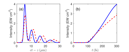
To show this, we modify Eqs. (1) by including the GVD term for the probe Toroker et al. (2012) , where , and is the group velocity of the seed. In Fig. 4, we compare amplification in a high-density plasma with a chirped plasma seed to amplification with a nonchirped plasma seed. The parameters are chosen similar to those in Ref. Toroker et al. (2012), i.e., , , , and the plasma length is . The plasma seeds are both Gaussian with FWHM of . The nonchirped seed has a uniform wave vector . Its output intensity reaches . Here, the wave vector, , of the chirped plasma seed increased per , where pump interacts with lower first. Since the pump has a constant frequency, the generated probe is also chirped with smaller wave numbers (smaller frequencies) at the front. Because of GVD, the probe contracts when traveling through the plasma. Similar to the case of a chirped laser seed Toroker et al. (2012), the probe beam has a larger growth rate and its intensity reaches . From Fig. 4(a), we also observe an appropriately narrower probe pulse.
Can any laser seed be replaced by an equivalent plasma wave seed? Clearly, for a seed laser pulse envelope that is not differentiable, the formal equivalent plasma seed envelope, according to Eq. (7), does not exist. However, this restriction on shape is not important since the seed laser pulse need be no more sharp than a Gaussian in order to access the -pulse pump depletion regime Tsidulko et al. (2002), for which equivalent plasma seeds do exist. More relevant is the restriction on the amplitude; while a seed laser pulse envelope can take an arbitrarily large amplitude, the Langmuir wave seed amplitude will be limited by the wave breaking limit. In a cold plasma, this condition is equivalent to a maximum density variation, ; in a warm plasma, the density variation is somewhat more limited Coffey (1971); Bergmann and Schnabl (1988). However, this will not be an issue in the main amplification regimes Clark and Fisch (2003), for which the necessary laser seeding amplitudes can be small Yampolsky et al. (2004). Also, even a small plasma wave seed can access operation near the wave breaking limit Edwards et al. (2015); Toroker et al. (2014), since that limit is determined by the pump amplitude, not the seed amplitude. The density restriction may be an issue, though in the so-called quasitransient regime, where damping of the Langmuir wave is significant, so amplification is achieved only with larger laser seed amplitudes Malkin and Fisch (2009). The corresponding amplitudes may then not be available for plasma wave seeds. However, these regimes are, in any event, not of interest for plasma wave seeding since, if the plasma wave is heavily damped, the advantage of synchronization is absent.
In summary, a Langmuir wave seed can, in principle, replace almost any useful laser seed in backward Raman amplifiers, generating a probe beam that has an identical wavefront. The method can also be generalized by using a chirped plasma wave wavelength to mimic the frequency chirping of a laser seed. These predictions are supported by hydrodynamic and fully kinetic 1D-PIC simulations. The promise of this method is that it represents an alternative technology in implementing compression of high-intensity lasers in plasma, with a particular advantage concerning the timing of the pulses.
Although the technological production of the plasma wave seed is beyond the scope of this work, one straightforward methodology would be to employ low-power high-quality counterpropagating laser pulses to produce the plasma wave seed; this seed would then linger in the plasma (it has near zero group velocity) until the high- power pump laser (which needs not be of high quality) excites the parametric interaction. In a plasma setting, localized plasma waves have been generated by stimulated Raman scattering using a tightly focused intense laser pulse in preformed plasma Kline et al. (2005); Rousseaux et al. (2006, 2009, 2016). The ability of plasma wave seeds to linger in plasma and then to scatter laser energy has already been exploited in a variety of settings, including plasma holography Dodin and Fisch (2002), plasma gratings Monchocé et al. (2014) and plasma photonic crystals Lehmann and Spatschek (2016, 2017). In dynamic Brillouin gratings in optical fibers and photonic chips Dong and Winful (2015); Santagiustina et al. (2013), the acoustic mode, playing the role of the plasma wave, can be arranged similarly to retain information. While the plasma seed is lingering, it might be manipulated to better serve as a seed, for example, through autoresonant techniques Barth et al. (2015). The possibilities outlined here should serve to stimulate the optimizing of means for generating the plasma wave seed. Moreover, the methodology offered here can be generalized to other waves with negligible group velocity that might mediate high-intensity laser compression in plasma, such as, for example, the ion acoustic wave for compression by stimulated Brillouin scattering.
Acknowledgements.
This work was supported by NNSA Grant No. DE-NA0002948, and AFOSR Grant No. FA9550-15-1-0391.References
- Strickland and Mourou (1985) D. Strickland and G. Mourou, “Compression of amplified chirped optical pulses,” Opt. Commun. 56, 219 (1985).
- Dubietis et al. (1992) A. Dubietis, G. Jonušauskas, and A. Piskarskas, “Powerful femtosecond pulse generation by chirped and stretched pulse parametric amplification in BBO crystal,” Opt. Commun. 88, 437 (1992).
- Shvets et al. (1998) G. Shvets, N. J. Fisch, A. Pukhov, and J. Meyer-ter-Vehn, “Superradiant amplification of an ultrashort laser pulse in a plasma by a counterpropagating pump,” Phys. Rev. Lett. 81, 4879 (1998).
- Malkin et al. (1999) V. M. Malkin, G. Shvets, and N. J. Fisch, “Fast compression of laser beams to highly overcritical powers,” Phys. Rev. Lett. 82, 4448 (1999).
- Dreher et al. (2004) M. Dreher, E. Takahashi, J. Meyer-ter-Vehn, and K.-J. Witte, “Observation of superradiant amplification of ultrashort laser pulses in a plasma,” Phys. Rev. Lett. 93, 095001 (2004).
- Ping et al. (2004) Y. Ping, W. Cheng, S. Suckewer, D. S. Clark, and N. J. Fisch, “Amplification of ultrashort laser pulses by a resonant Raman scheme in a gas-jet plasma,” Phys. Rev. Lett. 92, 175007 (2004).
- Cheng et al. (2005) W. Cheng, Y. Avitzour, Y. Ping, S. Suckewer, N. J. Fisch, M. S. Hur, and J. S. Wurtele, “Reaching the nonlinear regime of Raman amplification of ultrashort laser pulses,” Phys. Rev. Lett. 94, 045003 (2005).
- Ren et al. (2008) J. Ren, S. Li, A. Morozov, S. Suckewer, N. A. Yampolsky, V. M. Malkin, and N. J. Fisch, “A compact double-pass raman backscattering amplifier/compressor,” Phys. Plasmas 15, 056702 (2008).
- Ren et al. (2007) J. Ren, W. Cheng, S. Li, and S. Suckewer, “A new method for generating ultraintense and ultrashort laser pulses,” Nat. Phys. 3, 732–736 (2007).
- Yampolsky and Fisch (2011) N. A. Yampolsky and N. J. Fisch, “Limiting effects on laser compression by resonant backward Raman scattering in modern experiments,” Phys. Plasmas 18, 056711 (2011).
- Pai et al. (2008) C.-H. Pai, M.-W. Lin, L.-C. Ha, S.-T. Huang, Y.-C. Tsou, H.-H. Chu, J.-Y. Lin, J. Wang, and S.-Y. Chen, “Backward Raman amplification in a plasma waveguide,” Phys. Rev. Lett. 101, 065005 (2008).
- Ping et al. (2009) Y. Ping, R. K. Kirkwood, T.-L. Wang, D. S. Clark, S. C. Wilks, N. Meezan, R. L. Berger, J. Wurtele, N. J. Fisch, V. M. Malkin, E. J. Valeo, S. F. Martins, and C. Joshi, “Development of a nanosecond-laser-pumped Raman amplifier for short laser pulses in plasma,” Phys. Plasmas 16, 123113 (2009).
- Lehmann and Spatschek (2014) G. Lehmann and K. H. Spatschek, “Non-filamentated ultra-intense and ultra-short pulse fronts in three-dimensional Raman seed amplification,” Phys. Plasmas 21, 053101 (2014).
- Andreev et al. (2006) A. A. Andreev, C. Riconda, V. T. Tikhonchuk, and S. Weber, “Short light pulse amplification and compression by stimulated Brillouin scattering in plasmas in the strong coupling regime,” Phys. Plasmas 13, 053110 (2006).
- Lancia et al. (2010) L. Lancia, J.-R. Marquès, M. Nakatsutsumi, C. Riconda, S. Weber, S. Hüller, A. Mančić, P. Antici, V. T. Tikhonchuk, A. Héron, P. Audebert, and J. Fuchs, “Experimental evidence of short light pulse amplification using strong-coupling stimulated Brillouin scattering in the pump depletion regime,” Phys. Rev. Lett. 104, 025001 (2010).
- Weber et al. (2013) S. Weber, C. Riconda, L. Lancia, J.-R. Marquès, G. A. Mourou, and J. Fuchs, “Amplification of ultrashort laser pulses by Brillouin backscattering in plasmas,” Phys. Rev. Lett. 111, 055004 (2013).
- Lancia et al. (2016) L. Lancia, A. Giribono, L. Vassura, M. Chiaramello, C. Riconda, S. Weber, A. Castan, A. Chatelain, A. Frank, T. Gangolf, M. N. Quinn, J. Fuchs, and J.-R. Marquès, “Signatures of the self-similar regime of strongly coupled stimulated Brillouin scattering for efficient short laser pulse amplification,” Phys. Rev. Lett. 116, 075001 (2016).
- Edwards et al. (2016) M. R. Edwards, N. J. Fisch, and J. M. Mikhailova, “Strongly enhanced stimulated Brillouin backscattering in an electron-positron plasma,” Phys. Rev. Lett. 116, 015004 (2016).
- Shi et al. (2017) Y. Shi, H. Qin, and N. J. Fisch, “Laser-pulse compression using magnetized plasmas,” Phys. Rev. E 95, 023211 (2017).
- Ersfeld and Jaroszynski (2005) B. Ersfeld and D. A. Jaroszynski, “Superradiant linear Raman amplification in plasma using a chirped pump pulse,” Phys. Rev. Lett. 95, 165002 (2005).
- Peng et al. (2016) H. Peng, Z. H. Wu, Y. L. Zuo, Z. M. Zhang, K. N. Zhou, and J. Q. Su, “Single laser pulse compression via strongly coupled stimulated Brillouin scattering in plasma,” Phys. Plasmas 23, 073516 (2016).
- Tsidulko et al. (2002) Yu. A. Tsidulko, V. M. Malkin, and N. J. Fisch, “Suppression of superluminous precursors in high-power backward Raman amplifiers,” Phys. Rev. Lett. 88, 235004 (2002).
- Malkin and Fisch (2014) V. M. Malkin and N. J. Fisch, “Key plasma parameters for resonant backward Raman amplification in plasma,” Eur. Phys. J. Special Topics 223, 1157 (2014).
- Toroker et al. (2012) Z. Toroker, V. M. Malkin, and N. J. Fisch, “Seed laser chirping for enhanced backward Raman amplification in plasmas,” Phys. Rev. Lett. 109, 085003 (2012).
- Kruer (1988) W. L Kruer, The physics of laser plasma interactions (Reading, MA (US); Addison-Wesley Publishing Co., 1988).
- (26) See Supplemental Material for details of derivation, a discussion of the seeds equivalence in the nonlinear regime, and more PIC more simulation results at a higher temperature (50eV). .
- Shvets and Wurtele (1997) G. Shvets and J. S. Wurtele, “SASE in plasmas: Analysis and simulation of Raman backscatter from noise,” Nucl. Instrum. Meth. A 393, 371 (1997).
- Arber et al. (2015) T. D. Arber, K. Bennett, C. S. Brady, A. Lawrence-Douglas, M. G. Ramsay, N. J. Sircombe, P. Gillies, R. G. Evans, H. Schmitz, A. R. Bell, et al., “Contemporary particle-in-cell approach to laser-plasma modelling,” Plasma Phy. Contr. F. 57, 113001 (2015).
- (29) Simulations with higher electron temperatures () show the same correspondence between plasma wave seeding and laser seeding (see Supplemental Material).
- Coffey (1971) T. P. Coffey, “Breaking of large amplitude plasma oscillations,” Phys. Fluids 14, 1402 (1971).
- Bergmann and Schnabl (1988) A. Bergmann and H. Schnabl, “The influence of electron trapping on stationary Langmuir waves,” Phys. Fluids 31, 3266 (1988).
- Clark and Fisch (2003) D. S. Clark and N. J. Fisch, “Operating regime for a backward Raman laser amplifier in preformed plasma,” Phys. Plasmas 10, 3363 (2003).
- Yampolsky et al. (2004) N. A. Yampolsky, V. M. Malkin, and N. J. Fisch, “Finite-duration seeding effects in powerful backward Raman amplifiers,” Phys. Rev. E 69, 036401 (2004).
- Edwards et al. (2015) M. R. Edwards, Z. Toroker, J. M. Mikhailova, and N. J. Fisch, “The efficiency of Raman amplification in the wavebreaking regime,” Phys. Plasmas 22, 074501 (2015).
- Toroker et al. (2014) Z. Toroker, V. M. Malkin, and N. J. Fisch, “Backward Raman amplification in the Langmuir wavebreaking regime,” Phys. Plasmas 21, 113110 (2014).
- Malkin and Fisch (2009) V. M. Malkin and N. J. Fisch, “Quasitransient regimes of backward Raman amplification of intense X-ray pulses,” Phys. Rev. E 80, 046409 (2009).
- Kline et al. (2005) J. L. Kline, D. S. Montgomery, B. Bezzerides, J. A. Cobble, D. F. DuBois, R. P. Johnson, H. A. Rose, L. Yin, and H. X. Vu, “Observation of a transition from fluid to kinetic nonlinearities for Langmuir waves driven by stimulated Raman backscatter,” Phys. Rev. Lett. 94, 175003 (2005).
- Rousseaux et al. (2006) C. Rousseaux, L. Gremillet, M. Casanova, P. Loiseau, M. R. Le Gloahec, S. D. Baton, F. Amiranoff, J. C. Adam, and A. Héron, “Transient development of backward stimulated Raman and Brillouin scattering on a picosecond time scale measured by subpicosecond Thomson diagnostic,” Phys. Rev. Lett. 97, 015001 (2006).
- Rousseaux et al. (2009) C. Rousseaux, S. D. Baton, D. Bénisti, L. Gremillet, J. C. Adam, A. Héron, D. J. Strozzi, and F. Amiranoff, “Experimental evidence of predominantly transverse electron plasma waves driven by stimulated Raman scattering of picosecond laser pulses,” Phys. Rev. Lett. 102, 185003 (2009).
- Rousseaux et al. (2016) C. Rousseaux, K. Glize, S. D. Baton, L. Lancia, D. Bénisti, and L. Gremillet, “Experimental evidence of backward Raman scattering driven cooperatively by two picosecond laser pulses propagating side by side,” Phys. Rev. Lett. 117, 015002 (2016).
- Dodin and Fisch (2002) I. Y. Dodin and N. J. Fisch, “Storing, retrieving, and processing optical information by Raman backscattering in plasmas,” Phys. Rev. Lett. 88, 165001 (2002).
- Monchocé et al. (2014) S. Monchocé, S. Kahaly, A. Leblanc, L. Videau, P. Combis, F. Réau, D. Garzella, P. D’Oliveira, Ph. Martin, and F. Quéré, “Optically controlled solid-density transient plasma gratings,” Phys. Rev. Lett. 112, 145008 (2014).
- Lehmann and Spatschek (2016) G. Lehmann and K. H. Spatschek, “Transient plasma photonic crystals for high-power lasers,” Phys. Rev. Lett. 116, 225002 (2016).
- Lehmann and Spatschek (2017) G. Lehmann and K. H. Spatschek, “Laser-driven plasma photonic crystals for high-power lasers,” Phys. Plasmas 24, 056701 (2017).
- Dong and Winful (2015) M. Dong and H. G. Winful, “Area dependence of chirped-pulse stimulated Brillouin scattering: implications for stored light and dynamic gratings,” J. Opt. Soc. Am. B 32, 2514 (2015).
- Santagiustina et al. (2013) M. Santagiustina, S. Chin, N. Primerov, L. Ursini, and L. Thévenaz, “All-optical signal processing using dynamic Brillouin gratings,” Sci. Rep. 3, 1594 (2013).
- Barth et al. (2015) I. Barth, I. Y. Dodin, and N. J. Fisch, “Ladder climbing and autoresonant acceleration of plasma waves,” Phys. Rev. Lett. 115, 075001 (2015).