Anisotropy and suppression of spin–orbit interaction in a GaAs double quantum dot
Abstract
The spin-flip tunneling rates are measured in GaAs-based double quantum dots by time-resolved charge detection. Such processes occur in the Pauli spin blockade regime with two electrons occupying the double quantum dot. Ways are presented for tuning the spin-flip tunneling rate, which on the one hand gives access to measuring the Rashba and Dresselhaus spin–orbit coefficents. On the other hand they make it possible to turn on and off the effect of spin–orbit interaction with a high on/off-ratio. The tuning is accomplished by choosing the alignment of the tunneling direction with respect to the crystallographic axes, as well as by choosing the orientation of the external magnetic field with respect to the spin–orbit magnetic field. Spin-lifetimes of are achieved at a tunnel rate close to .
Spin–orbit interaction (SOI) couples the orbital motion of electrons to the spin via electric fields. Electrons moving in a crystal experience spin–orbit coupling originating from electric fields with bulk (Dresselhaus) and structure (Rashba) inversion asymmetries. Theoretical work predicts the SOI to bring about interesting physical phenomena, such as the quantum spin Hall effect Kane and Mele (2005); Murakami et al. (2003); Sinova et al. (2004) and, in conjuction with superconductivity, Majorana states in nanowires Sau et al. (2010). Large SOI can be used for driving spin qubits Nowack et al. (2007), and vanishing spin–orbit magnetic fields are required for observing a persistent spin-helix Koralek et al. (2009); Bernevig et al. (2006); Sasaki et al. (2014). Considering the varying influence of SOI in different systems, measuring its anisotropy and finding ways to tune its strength are essential for taking advantage of it.
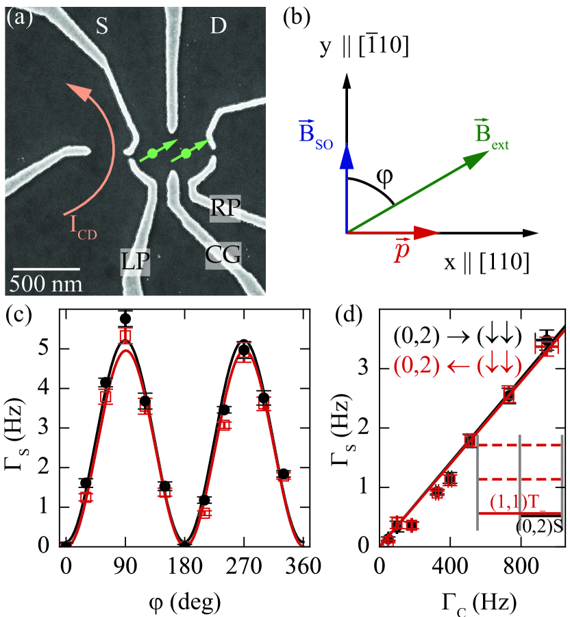
Despite the relevance of SOI for various experimental systems, only few experiments exist testing the effect of its anisotropy on spin relaxation in quantum dots which are candidates for qubits. Loss and DiVincenzo (1998); Imamoglu et al. (1999). It has been studied in single quantum dots Amasha et al. (2008); Scarlino et al. (2014); Könemann et al. (2005); Golovach et al. (2004, 2008); Khaetskii and Nazarov (2000, 2001); Fal’ko et al. (2005); Stano and Fabian (2006) with undefined direction of electron momentum and large energy gap between the different spin states Scarlino et al. (2014). In coupled quantum dots, theoretical studies predict anisotropic singlet–triplet splitting Burkard and Loss (2002); Stepanenko et al. (2003); Stano and Fabian (2006); Golovach et al. (2008); Stepanenko et al. (2012); Kavokin (2001); Danon (2013), and experimental evidence has been obtained recently in highly coupled dots but with ambiguity about the crystallographic direction of the main DQD axis defining the electron momentum Nichol et al. (2015). In this paper, we probe the SOI in GaAs by measuring spin-flip tunneling of individual electrons between energetically resonant (1,1) and (0,2) charge states of double quantum dots [see Fig. 1(a)] and with well-defined direction of electron tunneling. A magnetic field is applied in the plane of the underlying two-dimensional electron gas. In particular, we experimentally explore the two-fold anisotropy of the spin–orbit magnetic field
| (1) |
with respect to the crystallographic direction of electron motion, as well as with respect to the spin quantization axis given by the external magnetic field. In Eq. (1), and are the Rashba- and Dresselhaus coefficients, is Bohr’s magneton, and is the effective conduction band -factor of GaAs. Our results yield a thorough experimental verification of theoretically anticipated Stepanenko et al. (2012); Golovach et al. (2004) SOI effects, and allow for a strong suppression of spin-flip tunneling for electrons moving along the crystal direction as well as for external magnetic fields parallel to the internal spin–orbit field.
The relevance of SOI for electrons tunneling between two quantum dots in a GaAs/Al.3Ga.7As heterostructure is determined by the three factors illustrated in Fig. 1(b). First, there is the orientation of the crystal lattice defining the principal axes (-direction) and (-direction) in the (001)-plane of the electron gas. Second, there is the direction of tunneling between the quantum dots, which determines the orientation of the spin–orbit magnetic field in the same plane [Eq. (1)], as experienced by the tunneling electron. In our experiment we have chosen the tunneling direction to be along in device DQD 1 [shown in Fig. 1(a)] and along in a nominally identical device DQD 2 (not shown). Third, there is the quantization axis of the spins in the initial and final quantum dot states, which is chosen in our experiment by applying a magnetic field in the -plane at varying angles with respect to () for DQD 1 (DQD 2), i.e. with respect to the expected direction of . In an intuitive classical picture Stano and Fabian (2005) the spin–orbit magnetic field causes the spin to precess around the spin-quantization axis during the tunneling process. The precession angle, and therefore the spin-flip tunneling rate is maximum for , minimum for , and varies sinusoidally in-between. This oscillation provides the relevant handle for tuning the spin–orbit coupling strength in situ, as we will show in the following. By using a DQD for our study, the direction of motion of the tunnelling electron is well-defined and we can measure the influence of the SOI on possible qubit operations. In contrast to Ref. Nichol et al. (2015), the main DQD axis and therefore the direction of motion is known to point along for DQD1 and along for DQD2. The two devices show qualitatively different spin-flip rates. In particular, we find suppressed SOI for DQD2.
We apply , such that the (1,1)T- spin-triplet state with spin-configuration is the lowest energy state with one electron in each dot as shown in the inset of Fig. 1(d). The large Zeeman splitting of , much larger than at the electronic temperature , suppresses excitations to energetically higher spin-triplet states, and thereby freezes the spin-orientation within the individual QDs. We tune the spin-singlet state S with two electrons in the right dot into resonance with [see Fig. 1(d), inset], while suppressing tunneling to source and drain to a rate . Due to the different spin alignments of these states, each tunneling event between them requires a spin-flip. Using time-resolved detection of single-electron tunneling we measure the spin-flip tunneling rate in DQD 1 for the two individual resonant transitions . Varying the angle between and , we plot the two rates in Fig. 1(c) in red and black. Apparently, the spin-flip tunneling is completely suppressed for and significantly enhanced for . The suppression at parallel alignment is so strong that we observe no transitions on a time scale up to even though the tunnel coupling between the resonant states would allow for spin-conserving tunneling at a rate of about , as explained below. This is the most significant data reported in this paper.
By means of a charge-state dependent feedback Hofmann et al. (2016) (an explanation of this follows later in this paper) we additionally measure the spin-conserving tunneling rate . Figure 1(d) shows that the measured spin-flip tunneling rate is in this regime proportional to the spin-conserving tunneling rate . We vary this quantity by changing the voltage applied to the central gate CG [see Fig. 1(a)]. It has indeed been theoretically proposed Golovach et al. (2004); Danon (2013) that the spin-flip tunneling rate is given by
| (2) |
where is the inter-dot distance and the spin–orbit length Golovach et al. (2004). The spin–orbit length is a measure for the strength of the SOI. It is different for the two devices studied here: the plus sign is valid for tunneling along (DQD 1), and the minus sign for tunneling along (DQD 2). The numerical values of the Rashba ( and Dresselhaus () spin–orbit coefficients are unknown a-priori, and is the electron mass in GaAs. Our experimental results do indeed confirm the prediction (2) as we show in Figs. 1(c) and (d) by indicating fits to the theoretical prediction with red and black solid lines.
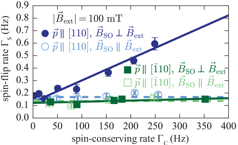
We now demonstrate that we can gradually increase the importance of dot-internal spin relaxation Golovach et al. (2004); Stano and Fabian (2006); Hanson et al. (2007); Scarlino et al. (2014) by reducing the strength of the external magnetic field to . This reduces the Zeeman energy to , which is now smaller than the thermal energy. Due to equipartitioning Reichl (2016), all four spin states, [] are occupied with similar probability. Spin-flip tunneling processes in this regime can be distinguished by their proportionality to from dot-internal spin relaxation with subsequent tunneling, which is independent of Maisi et al. (2016). The blue filled circles in Fig. 2 show the total spin-flip rate with for DQD 1 as is changed. The linear dependence differs from that in Fig. 1(d) by a vertical offset indicating a finite spin-flip rate within the individual quantum dots. In turn, aligning along in the same device leads to the blue open circles, which show essentially no dependence on in agreement with in Eq. (2), but have the same offset as the data of the case. It is evident from the data that we can write the total measured spin-flip rate as
| (3) |
where is the dot-internal spin-flip rate. As we observe this rate to be similar in the two DQD devices, we deduce that the hyperfine spin environment and the spin–orbit coupling strengths within a single dot [hence within the charge state (1,1)] are similar in all the dots. In contrast to Ref. Scarlino et al. (2014), we do not observe a large anisotropy in the dot-internal spin-flip rate. With the small Zeeman splitting in our experiment, dot-internal mixing of spin-states is primarily caused by hyperfine interaction Fujita et al. (2016), and thermal activation to all states is possible. The spin-flip processes in this setting differs from the spin-relaxation process from the excited spin-state to the ground-state with an energy gap of studied in Ref. Scarlino et al. (2014). In our experiments, we are interested in the spin-orbit mediated rate , which is measured by the contribution linear in to the spin-flip rate , as shown in Fig. 2.
Comparing these measurements taken on DQD 1 with those taken on DQD 2, where the direction of tunneling is along , gives the filled and open green squares in Fig. 2. Both orientations of , namely and give datapoints without a pronounced -dependence. This behavior can be attributed to the different values of in the two devices. From the vanishing SOI in DQD 2, we conclude that Studer et al. (2009); Koralek et al. (2009); Dettwiler et al. (2017); Schliemann et al. (2003); Bernevig et al. (2006) in our electron gas, which is device specific in general Koralek et al. (2009) and accidental in our case. Comparing the slopes of the two devices measured at , we determine an upper bound for the relative difference of the Rashba and Dresselhaus spin–orbit contribution and find that the SOI for electrons moving along is suppressed by a factor compared to the direction. Thus, the alignment of the DQD main axis with respect to the crystal axes allows for the selection of the spin–orbit field experienced by the tunneling electrons. With a separation of the two quantum dots, we estimate , which agrees well with spin–orbit lengths of a few found in the literature Nowack et al. (2007); Nichol et al. (2015); Maisi et al. (2016).
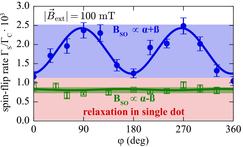
Figure 3 shows the full angle-dependence of for both devices with . In agreement with Eq. (3), DQD 1 (filled blue circles) shows the strong oscillatory contribution to originating from given in Eq. (2), but vertically offset by . In contrast, the open green squares of DQD 2 show only a very weak angle-dependence, in agreement with the weak spin–orbit interaction effect experienced by an electron tunneling in direction (c.f. Fig. 2). The solid lines are sinusoidal fits to Eqs. (3) and (2) with , and a phase offset as fitting parameters. The phase offset accounts for an uncertainty in the alignment of the sample with respect to the magnetic field and is in DQD 1. In this measurement, the rate was found to be independent of the angle . Summing up our results demonstrated in Figs. 2 and 3, we used Eq. (3) to distinguish spin-flip tunnelling from dot-internal relaxation processes. We showed that the spin-orbit interaction is suppressed for an electron tunneling along . For tunneling along , spin-flip tunnelling is reduced for the field directions and .
We now present the technical details of our experiment and of the measurements of and . Our devices are formed in a GaAs/AlGaAs heterostructure containing a two-dimensional electron gas below the surface. The electron density and mobility are and , respectively, as measured at . Negative voltages applied to the metallic top gates [light-grey fingers in Fig. 1(a)] deplete the two-dimensional electron gas below the gates and confine the electrons (green circles with arrows) in DQD s Hanson et al. (2007).
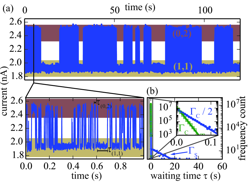
We measure the charge state of the DQD by means of the current through a quantum point contact charge detector coupled capacitively to the DQD-device [see Fig. 1(a)] Vandersypen et al. (2004); Schleser et al. (2004). The time-trace of presented in Fig. 4(a) was taken with , i.e. larger than the Overhauser field Jouravlev and Nazarov (2006); Koppens et al. (2005). It shows transitions between the and states. In the topmost panel, we observe that occasionally the tunneling becomes halted for several seconds as a result of Pauli spin blockade Ono et al. (2002); Johnson et al. (2005); Fujita et al. (2016, 2015); Maisi et al. (2016) at small magnetic fields: if the spins of the two electrons in the state are parallel [spin states or ], a spin-flip is required for a transition to the state, where the spins of the electrons are anti-parallel Hanson et al. (2007). On the other hand, fast tunneling events occur between the and the unpolarized states [spin states ], where no spin-flip is required. The distribution of waiting times in the state [see the zoom of Fig. 4(a) for the definition of this quantity] is presented in Fig. 4(b) with filled blue circles and shows two characteristic time scales, see also Refs. Maisi et al. (2016); Fujita et al. (2016). We associate the fast one with the spin conserving tunneling rate, , set by the tunnel-coupling between the two quantum dots. The slow time-scale is associated with transitions requiring a spin-flip and is a measure for the spin-flip rate .
Finally we briefly explain the operation of the charge-dependent feedback mechanism used to determine in the data shown in Fig. 1. When both electrons are detected in the same dot, the level is shifted into resonance with the unpolarized states. The measured waiting time for tunneling into one of these states yields the spin-conserving rate . The rate weakly depends on the in-plane angle with a sinusoidal amplitude smaller than . Possible origins are the confinement of the wave–functions perpendicular to the field direction, and spin-flip tunnelling combined with a relaxation into the state.
In conclusion, we have demonstrated experimentally the two-fold anisotropy of the spin–orbit interaction. We showed that the strength of the spin–orbit field depends on the direction of electron tunneling and, in our device, vanishes for the electron tunneling along . We were able to extract values for the spin–orbit coefficients and from our observations. Along two well-defined directions of electron tunneling, we measured the anisotropy of the spin–orbit interaction brought about by the relative alignment between spin quantization axis and the spin–orbit field and observed the theoretically expected sinusoidal dependence. Our measurements at magnetic fields, where the Zeeman splitting exceeds temperature, demonstrate the suppression of spin relaxation processes within single dots. The high tunability of the spin-flip tunneling rate and the absence of the incoherent processes found in this configuration are promising for coherent spin operations in DQD s. Beyond that our measurement technique lends itself for similar studies in different material systems, where few or no studies of the anisotropy of spin–orbit interaction are available.
Acknowledgements.
We acknowledge contributions by Simon Parolo. We thank Mattias Beck, Peter Stano, Gian Salis and Patrick Altmann for stimulating discussions and Daniel Loss for valuable feedback on the manuscript. This work was supported by the Swiss National Science Foundation (SNF) through the National Center of Competence in Research Quantum Science and Technology (NCCR QSIT) and by Eidgenössische Technische Hochschule (ETH) Zürich.References
- Kane and Mele (2005) C. L. Kane and E. J. Mele, Phys. Rev. Lett. 95, 226801 (2005).
- Murakami et al. (2003) S. Murakami, N. Nagaosa, and S.-C. Zhang, Science 301, 1348 (2003).
- Sinova et al. (2004) J. Sinova, D. Culcer, Q. Niu, N. A. Sinitsyn, T. Jungwirth, and A. H. MacDonald, Phys. Rev. Lett. 92, 126603 (2004).
- Sau et al. (2010) J. D. Sau, R. M. Lutchyn, S. Tewari, and S. Das Sarma, Phys. Rev. Lett. 104, 040502 (2010).
- Nowack et al. (2007) K. C. Nowack, F. H. L. Koppens, Y. V. Nazarov, and L. M. K. Vandersypen, Science 318, 1430 (2007).
- Koralek et al. (2009) J. D. Koralek, C. P. Weber, J. Orenstein, B. A. Bernevig, S.-C. Zhang, S. Mack, and D. D. Awschalom, Nature 458, 610 (2009).
- Bernevig et al. (2006) B. A. Bernevig, J. Orenstein, and S.-C. Zhang, Phys. Rev. Lett. 97, 236601 (2006).
- Sasaki et al. (2014) A. Sasaki, S. Nonaka, Y. Kunihashi, M. Kohda, T. Bauernfeind, T. Dollinger, K. Richter, and J. Nitta, Nat Nano 9, 703 (2014).
- Loss and DiVincenzo (1998) D. Loss and D. P. DiVincenzo, Phys. Rev. A 57, 120 (1998).
- Imamoglu et al. (1999) A. Imamoglu, D. D. Awschalom, G. Burkard, D. P. DiVincenzo, D. Loss, M. Sherwin, and A. Small, Phys. Rev. Lett. 83, 4204 (1999).
- Amasha et al. (2008) S. Amasha, K. MacLean, I. P. Radu, D. M. Zumbühl, M. A. Kastner, M. P. Hanson, and A. C. Gossard, Phys. Rev. Lett. 100, 046803 (2008).
- Scarlino et al. (2014) P. Scarlino, E. Kawakami, P. Stano, M. Shafiei, C. Reichl, W. Wegscheider, and L. Vandersypen, Phys. Rev. Lett. 113, 256802 (2014).
- Könemann et al. (2005) J. Könemann, R. J. Haug, D. K. Maude, V. I. Fal’ko, and B. L. Altshuler, Phys. Rev. Lett. 94, 226404 (2005).
- Golovach et al. (2004) V. N. Golovach, A. Khaetskii, and D. Loss, Phys. Rev. Lett. 93, 016601 (2004).
- Golovach et al. (2008) V. N. Golovach, A. Khaetskii, and D. Loss, Phys. Rev. B 77, 045328 (2008).
- Khaetskii and Nazarov (2000) A. V. Khaetskii and Y. V. Nazarov, Phys. Rev. B 61, 12639 (2000).
- Khaetskii and Nazarov (2001) A. V. Khaetskii and Y. V. Nazarov, Phys. Rev. B 64, 125316 (2001).
- Fal’ko et al. (2005) V. I. Fal’ko, B. L. Altshuler, and O. Tsyplyatyev, Phys. Rev. Lett. 95, 076603 (2005).
- Stano and Fabian (2006) P. Stano and J. Fabian, Phys. Rev. B 74, 045320 (2006).
- Burkard and Loss (2002) G. Burkard and D. Loss, Phys. Rev. Lett. 88, 047903 (2002).
- Stepanenko et al. (2003) D. Stepanenko, N. E. Bonesteel, D. P. DiVincenzo, G. Burkard, and D. Loss, Phys. Rev. B 68, 115306 (2003).
- Stepanenko et al. (2012) D. Stepanenko, M. Rudner, B. I. Halperin, and D. Loss, Phys. Rev. B 85, 075416 (2012).
- Kavokin (2001) K. V. Kavokin, Phys. Rev. B 64, 075305 (2001).
- Danon (2013) J. Danon, Phys. Rev. B 88, 075306 (2013).
- Nichol et al. (2015) J. M. Nichol, S. P. Harvey, M. D. Shulman, A. Pal, V. Umansky, E. I. Rashba, B. I. Halperin, and A. Yacoby, Nature Communications 6, 7682 (2015).
- Stano and Fabian (2005) P. Stano and J. Fabian, Phys. Rev. B 72, 155410 (2005).
- Hofmann et al. (2016) A. Hofmann, V. Maisi, C. Gold, T. Krähenmann, C. Rössler, J. Basset, P. Märki, C. Reichl, W. Wegscheider, K. Ensslin, and T. Ihn, Phys. Rev. Lett. 117, 206803 (2016).
- Hanson et al. (2007) R. Hanson, L. P. Kouwenhoven, J. R. Petta, S. Tarucha, and L. M. K. Vandersypen, Rev. Mod. Phys. 79, 1217 (2007).
- Reichl (2016) L. E. Reichl, A modern course in statistical physics, 4th ed. (Wiley-VCH Verlag GmbH & Co. KGaA, Weinheim, 2016) oCLC: 927845638.
- Maisi et al. (2016) V. F. Maisi, A. Hofmann, M. Röösli, J. Basset, C. Reichl, W. Wegscheider, T. Ihn, and K. Ensslin, Physical Review Letters 116, 136803 (2016).
- Fujita et al. (2016) T. Fujita, P. Stano, G. Allison, K. Morimoto, Y. Sato, M. Larsson, J.-H. Park, A. Ludwig, A. Wieck, A. Oiwa, and S. Tarucha, Phys. Rev. Lett. 117, 206802 (2016).
- Studer et al. (2009) M. Studer, G. Salis, K. Ensslin, D. C. Driscoll, and A. C. Gossard, Phys. Rev. Lett. 103, 027201 (2009).
- Dettwiler et al. (2017) F. Dettwiler, J. Fu, S. Mack, P. J. Weigele, J. C. Egues, D. D. Awschalom, and D. M. Zumbühl, arXiv:1702.05190 [cond-mat] (2017), arXiv: 1702.05190.
- Schliemann et al. (2003) J. Schliemann, J. C. Egues, and D. Loss, Phys. Rev. Lett. 90, 146801 (2003).
- Vandersypen et al. (2004) L. M. K. Vandersypen, J. M. Elzerman, R. N. Schouten, L. H. W. v. Beveren, R. Hanson, and L. P. Kouwenhoven, Applied Physics Letters 85, 4394 (2004).
- Schleser et al. (2004) R. Schleser, E. Ruh, T. Ihn, K. Ensslin, D. C. Driscoll, and A. C. Gossard, Applied Physics Letters 85, 2005 (2004).
- Jouravlev and Nazarov (2006) O. N. Jouravlev and Y. V. Nazarov, Phys. Rev. Lett. 96, 176804 (2006).
- Koppens et al. (2005) F. H. L. Koppens, J. A. Folk, J. M. Elzerman, R. Hanson, L. H. W. v. Beveren, I. T. Vink, H. P. Tranitz, W. Wegscheider, L. P. Kouwenhoven, and L. M. K. Vandersypen, Science 309, 1346 (2005).
- Ono et al. (2002) K. Ono, D. G. Austing, Y. Tokura, and S. Tarucha, Science 297, 1313 (2002).
- Johnson et al. (2005) A. C. Johnson, J. R. Petta, C. M. Marcus, M. P. Hanson, and A. C. Gossard, Phys. Rev. B 72, 165308 (2005).
- Fujita et al. (2015) T. Fujita, K. Morimoto, H. Kiyama, G. Allison, M. Larsson, A. Ludwig, S. R. Valentin, A. D. Wieck, A. Oiwa, and S. Tarucha, arXiv:1504.03696 [cond-mat, physics:quant-ph] (2015), arXiv: 1504.03696.