omotani@chalmers.se
Edge Momentum Transport by Neutrals: an Interpretive Numerical Framework
Abstract
Due to their high cross-field mobility, neutrals can contribute to momentum transport even at the low relative densities found inside the separatrix and they can generate intrinsic rotation. We use a charge-exchange dominated solution to the neutral kinetic equation, coupled to neoclassical ions, to evaluate the momentum transport due to neutrals. Numerical solutions to the drift-kinetic equation allow us to cover the full range of collisionality, including the intermediate levels typical of the tokamak edge. In the edge there are several processes likely to contribute to momentum transport in addition to neutrals. Therefore, we present here an interpretive framework that can evaluate the momentum transport through neutrals based on radial plasma profiles. We demonstrate its application by analysing the neutral angular momentum flux for an L-mode discharge in the ASDEX Upgrade tokamak. The magnitudes of the angular momentum fluxes we find here due to neutrals of up to are comparable to the net torque on the plasma from neutral beam injection, indicating the importance of neutrals for rotation in the edge.
1 Introduction
Momentum transport in the tokamak edge is a crucial issue since rotation suppresses magnetohydrodynamic instabilities such as resistive wall modes [1] and flow shear in the edge suppresses turbulence, leading to high-confinement mode (H-mode) operation [2]. Neutral particles are always present in the edge of the confined plasma volume, and despite their low relative density can contribute strongly to transport due to their high cross-field mobility, as has been demonstrated theoretically [3, 4, 5, 6, 7, 8, 9, 10, 11, 12]. The influence of neutrals on confinement has also been observed experimentally [13, 14, 15] and the poloidal location of gas-fuelling, inboard versus outboard, has been seen to be important for the low- to high-confinement transition threshold [16, 17, 18].
It has been shown previously that when neutrals dominate the angular momentum transport, the radial electric field and hence toroidal rotation can be self-consistently calculated [10, 11, 12]. It was also shown that the neutrals can generate intrinsic rotation, since a toroidal heat flux in the ions drives a radial flux of angular momentum through neutrals, as explained in [11]. However, there will be other contributions, potentially of similar or greater magnitude, for instance from turbulence, ion orbit losses [19, 20], non-axisymmetric magnetic fields [21] or finite orbit width effects [22]. It is therefore important to evaluate the momentum transport due to neutrals from experimental profiles, so that the magnitudes of the various effects can be compared. Analytical solutions [10, 11] rely on asymptotic ordering of the collisionality into the Pfirsch-Schlüter (high collisionality) or banana (low collisionality) regimes. However, the conditions typical in the edge plasma produce order unity collisionality, for example for the profiles we show in Section 3, where is the thermal velocity, the ion-ion collision rate and the parallel connection length. In order to relax this restriction numerical solutions of the drift-kinetic equation must be used. Recently, the radial electric field and toroidal rotation have been calculated numerically from the constraint that the angular momentum flux through neutrals vanishes in steady state in the absence of external torque [12] that is, as noted above, assuming that the neutrals dominate the momentum transport and also that the radial gradient of the neutrals is the dominant profile gradient. The latter assumption makes the calculation of the momentum flux local (otherwise it would depend on, for instance, the radial gradient of the toroidal rotation and hence on second derivatives of the density, temperature, etc.). Here, in order to avoid these assumptions, we introduce a new approach which takes the background plasma profiles, including the radial electric field, as given, allowing us to calculate the angular momentum flux through neutrals directly, without requiring that they are the only channel for momentum transport. This provides an interpretive tool that can be applied to experimental data in order to compare the magnitude of the neutral momentum transport to other mechanisms and to external sources of momentum such as neutral beam injection (NBI) heating. The interpretive approach is derived in Section 2 and applied to an L-mode discharge from ASDEX Upgrade (AUG) in Section 3. We discuss the implications of the results in Section 4.
2 Neutral momentum transport
We outline here the calculation of the angular momentum flux through neutrals, which are coupled by charge exchange to kinetic ions. Integrated over a flux surface, the radial flux of toroidal angular momentum carried by the neutral population is where is the stress tensor of the neutrals, is the distribution function of the neutrals, is the poloidal flux, is the volume enclosed by a flux surface, a prime denotes a derivative with respect to , is the major radius, with the toroidal angle (increasing in the co-current direction), and is the mass of the ions or neutrals.
Our solution to the kinetic equation for relies on several approximations. We take a short charge-exchange (CX) mean-free-path (MFP) expansion; although the MFP is not always short compared to profile length scales in the edge, it was found in [9] that the approximation is surprisingly accurate, compared to a full solution allowing arbitrary MFP for a special class of self-similar profiles. We neglect ionization, but this is most important for the determination of the neutral density profile, which we take as an input; ionization affects the momentum transport only by changing the effective collision rate [6]. We use a simplified CX collision operator [4] that allows us to close the neutral kinetic equation in an efficient way [6], as described below. These approximations allow us to avoid the computational expense of Monte Carlo neutral codes, e.g. EIRENE [23], while retaining coupling to the kinetic ion distribution, rather than only a drifting Maxwellian as implemented in [23].
The steady state neutral kinetic equation then takes the form [6]
| (1) |
where and are the neutral and ion densities and is the ion distribution function. is the characteristic rate for charge-exchange interactions with the thermal charge exchange rate, where for Deuterium ions and neutrals at [24], which is a typical temperature value of the profiles we use in Section 3. Solving perturbatively for small , where is the thermal speed and is a characteristic length scale of the background profiles,
| (2) | ||||
| (3) |
contributes a term to the angular momentum flux which, being proportional to , is negligible at in the gyroradius expansion [25], where and is the gyroradius. Thus we need keep only and so
| (4) |
neglecting and using the identities for any [25] and 111This identity follows from the fact that is a symmetric tensor, while is antisymmetric.. Including the gyroradius correction, the ion distribution function at the particle position is
| (5) |
where is a Maxwellian, is the gyroradius vector with the guiding centre position, is the poloidally varying part of the electrostatic potential and 0, 1 subscripts refer to the order in . The first two terms do not contribute to (4) as they are isotropic in . We obtain the non-adiabatic piece of the perturbed distribution function, from numerical solutions of the first order drift kinetic equation using the perfect neoclassical solver (run here in radially-local mode) [26], which assume that the flow is subsonic, .
As noted in the introduction, this system was used to explore the effects of magnetic geometry and collisionality on intrinsic rotation driven by momentum transport through neutrals [12, 27]. In the next section we introduce the interpretive framework which can be used to diagnose experimental results.
3 Interpretive modelling of momentum flux
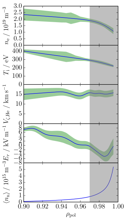
We have evaluated the angular momentum flux through neutrals for L-mode profiles from the AUG discharge #26601, shown in FIG. 1, in order to demonstrate the potential of our interpretive tool. This takes profiles of ion density and temperature , radial electric field and neutral density as inputs to calculate the angular momentum flux as described in the previous section. It is also possible to constrain the neoclassical solutions with the toroidal rotation profile of any ion species instead of .
For the AUG case, CXRS measurements were performed on the impurity to measure the ion temperature (assumed equal to the temperature) and infer the radial electric field [28]. Electron density was measured with the Thomson scattering, Lithium beam and interferometry diagnostics; we neglect the impurity density, taking . Profiles are plotted as functions of the normalized flux label where is the value of at the separatrix and we take at the magnetic axis.
To obtain neutral density profiles, we ran KN1D [29], extending the plasma profiles (taking ) into the scrape-off layer as exponentials, with decay lengths of 3 cm for the density and 0.5 cm for the temperature. KN1D’s molecular pressure input was chosen to give a value of at the separatrix, consistent with the low-field side neutral density modelled in [30]. We use the output of KN1D to set the flux surface average of the neutral density , which we keep fixed while choosing different poloidal profiles in FIGs. 2 and 3.
Within a drift-orbit width of the separatrix, the ion distribution function is likely to depart strongly from the conventional neoclassical prediction due to orbit loss effects [19, 20], which we do not consider here. We therefore exclude this region in the presentation of our results, as indicated by the shaded regions in the figures.
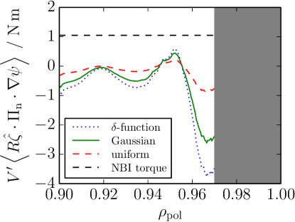
For poloidally uniform neutrals, the outward flux of co-current toroidal angular momentum passing through a flux surface reaches nearly , as shown in FIG. 2. The discharge had of NBI heating with particles; the momentum is deposited at a tangency radius and so the external momentum input from the NBI is (indicated as the dashed horizontal line in FIG. 2), of a similar magnitude to the momentum flux carried by the neutrals. This gives the net outward flux of angular momentum carried by all mechanisms through our simulation domain at the plasma edge, assuming that the NBI momentum is predominantly deposited in the core plasma and provides the only source of angular momentum.
The neutrals thus carry a significant angular momentum flux near the plasma edge and can be expected to play an important role in regulating the plasma rotation in L-mode.
For comparison one can make a simple estimate of the angular momentum flux. Assume that the fast neutrals, those coming from a charge exchange reaction with a hot ion in the confined plasma, escape immediately from the confined region. Then the total momentum carried out of the plasma is where is the total inward flux of neutrals (estimated from the flux density across the separatrix of simulated by KN1D), is a typical toroidal rotation velocity and is a typical radius in the outboard edge region of the plasma. This estimate is similar in magnitude to our prediction but has the opposite sign; this is a consequence of the very different assumptions made. For this estimate each neutral experiences only one CX interaction and acts purely as a momentum sink. On the other hand in the short MFP model we use, each neutral undergoes several CX interactions. The direction of the flux (inward or outward) is then influenced by the directions of the gradients in both neutral density and plasma toroidal rotation, heat flux, etc. because neutrals exchange momentum between different flux surfaces. In particular there can be an inward pinch of momentum due to the density gradient of the neutrals; on a given flux surface there are more neutrals coming from the outside than the inside, all carrying the momentum picked up from a CX reaction with an ion. Note that, as we see in FIG. 1, the toroidal rotation does not change much across our domain; thus the momentum carried by each inward or outward going particle will be similar, so that this effect gives rise to an inward flux of angular momentum.
Poloidal localization of the neutrals can enhance the angular momentum flux. In FIG. 2 we compare the momentum flux for three different assumed poloidal profiles: uniform, Gaussian (with standard deviation ) or -function. The localized profiles are centred at the outboard midplane. For ease of comparison we have used the same flux-surface averaged neutral density profile for all of the curves. In reality, the neutral distribution will be some combination of a roughly uniform piece from wall recycling and a localized part near the gas fuelling valve (represented by the Gaussian shape here), so the enhancement above the uniform level due to outboard localization could be expected to be more moderate than the limiting case shown. Previous work, both analytical [10, 11] and numerical [12], used -function localized neutrals for convenience. We can see from FIG. 2 that there is not a major difference between this approximation and the case of neutrals localized as a Gaussian, with both the trends and order of magnitude being correctly captured, although the sharper localization of the -function does further enhance the momentum flux.
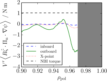
The neutrals provide more effective transport of toroidal angular momentum when they are on the outboard side of the tokamak than on the inboard side or near the X-point, due to the larger major radius and poloidal magnetic field , as can be seen from (4), noting that . This is confirmed by FIG. 3 which compares the momentum flux through Gaussian localized neutrals centred at the outboard midplane, inboard midplane and adjacent to the X-point, highlighting the importance of the poloidal location of the neutrals for the angular momentum flux that they carry.
4 Discussion
We have demonstrated here that charge-exchanging neutrals can carry a significant angular momentum flux in the tokamak edge. The formalism developed in [10, 11] and first implemented numerically in [12] has been extended, to enable interpretive studies evaluating the momentum transport through neutrals for experimental profiles and equilibria. In this interpretive mode, the radial variation of the background profiles does not have to be neglected compared to the radial gradient of the neutral density. We model an L-mode discharge from AUG to demonstrate this capability and show that a significant flux of angular momentum, comparable in magnitude to the total momentum input from NBI, can be carried by the neutrals, motivating further application to experimental data in future.
The approach taken here allows rapid experimentation with parameters and profiles and provides both qualitative insight and at least order of magnitude estimates of the momentum transport due to neutrals. Despite the limitations of the modelling described here, some conclusions are clear. The strength of the neutral momentum transport is much larger for neutrals located on the outboard side of the tokamak than on the inboard side. This is due both to the smaller moment of force at smaller major radius and to the smaller physical-space gradients of flux-function plasma profiles which have poloidally constant gradients in -space, as is smaller on the inboard side. Likewise near the X-point, where is small, the influence of the neutrals will be weak. Thus the influence of neutrals on the plasma rotation may be minimized by fuelling from the inboard side or X-point. On the other hand, if it is desired to drive intrinsic rotation using the neutral angular momentum flux [10, 11, 12], then this will compete more effectively with other momentum transport channels if the neutrals are located on the outboard side and may be able to generate substantial radial electric fields in H-mode pedestals.
Intrinsic rotation is particularly important for future tokamaks such as ITER since the angular momentum source from NBI heating will be weaker in larger devices. The interesting case is that with steep temperature profiles in H-mode and although our modelling is restricted to L-mode plasmas, it is in the region where the edge transport barrier will form in H-mode that neutrals are most important. However, modelling steep temperature gradients is extremely challenging since the deviation of the bulk ion distribution from a Maxwellian distribution is not small, so that a non-linear collision operator is needed, and the steep gradients also necessitate radially-global solutions. State of the art numerical solutions of the neutral kinetic equation couple only to a drifting-Maxwellian plasma [23]. However, the temperature gradient driven departure of the ions from a local Maxwellian distribution drives an angular momentum flux in the neutral distribution function [4, 11]. Thus when the external torque is large, so that the rotation-driven momentum flux dominates, the drifting-Maxwellian description of the bulk plasma is sufficient, but when there are steep temperature gradients, or for intrinsic rotation where the external torque vanishes, a kinetic model for the plasma is needed. In the linear region we have considered, where standard neoclassical theory and modelling are valid, the transport is proportional to the gradients, so significantly stronger momentum transport through neutrals may be expected to arise in steep gradient regions, such as the H-mode pedestal. Quantitative evaluation, requiring the development of more sophisticated codes coupling fully kinetic neutrals to kinetic ions, remains a challenging subject for future research, which can build on existing progress in neoclassical pedestal modelling [31, 26, 32, 33].
Acknowledgements
The authors are grateful to Matt Landreman for advice and help with the perfect code and to Stuart Henderson for assistance with the ADAS database. We also thank Prof. Arne Kallenbach and Dr. Rachael McDermott for carefully reading the manuscript. This work was supported by the Framework grant for Strategic Energy Research (Dnr. 2014-5392) and the International Career Grant (Dnr. 330-2014-6313) from Vetenskapsrådet.
References
- [1] HENDER, T. et al., Nucl. Fusion 47 (2007) S128.
- [2] TERRY, P. W., Rev. Mod. Phys. 72 (2000) 109.
- [3] HAZELTINE, R. et al., Nucl. Fusion 32 (1992) 3.
- [4] CATTO, P. J., Phys. Plasmas 1 (1994) 1936.
- [5] HELANDER, P. et al., Phys. Plasmas 1 (1994) 3174.
- [6] CATTO, P. J. et al., Phys. Plasmas 5 (1998) 3961.
- [7] FÜLÖP, T. et al., Phys. Plasmas 5 (1998) 3398.
- [8] FÜLÖP, T. et al., Phys. Plasmas 5 (1998) 3969.
- [9] FÜLÖP, T. et al., Phys. Plasmas 8 (2001) 5214.
- [10] FÜLÖP, T. et al., Phys. Rev. Lett. 89 (2002) 225003.
- [11] HELANDER, P. et al., Phys. Plasmas 10 (2003) 4396.
- [12] OMOTANI, J. et al., Nuclear Fusion 56 (2016) 124002.
- [13] VERSLOOT, T. W. et al., Plasma Phys. Controlled Fusion 53 (2011) 065017.
- [14] JOFFRIN, E. et al., Impact of divertor geometry on ITER scenarios performance in the JET metallic wall, in 25th IAEA Fusion Energy Conference, 2014, EX/P5-40.
- [15] TAMAIN, P. et al., J. Nucl. Mater. 463 (2015) 450.
- [16] FUKUDA, T. et al., Plasma Phys. Controlled Fusion 42 (2000) A289.
- [17] VALOVIC, M. et al., Plasma Phys. Controlled Fusion 44 (2002) A175.
- [18] FIELD, A. R. et al., Plasma Phys. Controlled Fusion 46 (2004) 981.
- [19] SHAING, K. C. et al., Phys. Rev. Lett. 63 (1989) 2369.
- [20] STOLTZFUS-DUECK, T., Phys. Plasmas 19 (2012).
- [21] NAVE, M. F. F. et al., Phys. Rev. Lett. 105 (2010) 105005.
- [22] PUSZTAI, I. et al., Plasma Phys. Control. Fusion 58 (2016) 085001.
- [23] REITER, D. et al., Fusion Sci. Technol. 47 (2005) 172.
- [24] SUMMERS, H. P., The ADAS User Manual, v. 2.6, http://www.adas.ac.uk, 2004.
- [25] HELANDER, P. et al., Collisional transport in magnetized plasmas, Cambridge University Press, 2002.
- [26] LANDREMAN, M. et al., Plasma Phys. Controlled Fusion 56 (2014) 045005.
- [27] OMOTANI, J. T. et al., J. Phys. Conf. Ser. (2016) in press.
- [28] VIEZZER, E. et al., Nucl. Fusion 53 (2013) 053005.
- [29] LABOMBARD, B., KN1D: A 1-D space, 2-D velocity, kinetic transport algorithm for atomic and molecular hydrogen in an ionizing plasma, Plasma Science and Fusion Center, Massachusetts Institute of Technology, 2001.
- [30] VIEZZER, E. et al., Plasma Physics and Controlled Fusion 53 (2011) 035002.
- [31] CATTO, P. J. et al., Plasma Phys. Control. Fusion 55 (2013) 045009.
- [32] BATTAGLIA, D. J. et al., Phys. Plasmas 21 (2014) 072508.
- [33] DORF, M. A. et al., Phys. Plasmas 23 (2016) 056102.