Structure of chambers cut out by Veronese arrangements of hyperplanes in the real projective spaces
Introduction
Consider several lines in the real projective plane. The lines divide the plane in various chambers. We are interested in the arrangement of the chambers. This problem is quite naive and simple. But if the cardinality of the lines are large, there are no way to control in general. If we assume that no three lines meet at a point (line arrangements in general position), the situation does not improve much. In this paper we always assume this. Let us observe when is small. Since we are mathematicians, we start from : The projective plane itself. When , what remains is the euclidean plane, of course. When , the plane is divided in two di-angular chambers.
When , the lines cut out four triangles; if we think one of the lines is the line at infinity, then the remaining two can be considered as two axes dividing the euclidean plane in four parts. Another explanation: if we think that the three lines bound a triangle, then around the central triangle there is a triangle along each edge/vertex.
When , four triangles and three quadrilaterals are arranged as follows; if we think one of the lines is the line at infinity, then the remaining three lines bound a triangle, and around this triangle there are a quadrilateral along each edge, and a triangle kissing at each vertex. Another explanation: put the four lines as the symbol , then around the central quadrilateral are a triangle along each edge, and a quadrilateral kissing at each pair of opposite vertices. The situation is already not so trivial.
When , there is a unique pentagon, and if we see the arrangement centered at this pentagon, the situation can be described simply: there are five triangles adjacent to five edges, and five quadrilaterals kissing at five vertices. If we think one of the lines is the line at infinity, the remaining four lines can not be like since the five lines should be in general position; the picture does not look simple, but one can find a pentagon. Thanks to the central pentagon, we can understand well the arrangement.
When , there are four types of arrangements. The simplest one has a hexagon surrounded by six triangles along the six edges; there are six quadrilaterals kissing at the six vertices, and three quadrilaterals away from the hexagon. Another one with icosahedral symmetry: If we identify the antipodal points of the dodeca-icosahedron projected from the center onto a sphere we get six lines in the projective plane: there are triangles and pentagons. We do not describe here the two other types.
For general there are so many types, and we can not find a way to control them, unless the lines bound an -gon, from which we can see the arrangement. We can think this -gon as the center of this arrangement, and we would like to study higher dimensional versions of this kind of arrangements with center, if such a chamber exists. Before going further, since we are mathematicians, we start from the very beginning: the -dimensional projective space is an empty set; well it is a bit difficult to find something interesting. The -dimensional projective space is a point; this point would be the center, OK. Now we proceed to the projective line. points on the line divide the line into intervals. (In this case ‘in general position’ means ‘distinct’.) Very easy, but there is no center in the arrangement!
How about 3-dimensional case? We have planes in general position (no four planes meet at a point). : The projective space itself. When , what remains is the euclidean space, of course. When , the space is divided into two di-hedral chambers. When , the space is divided into four tri-hedral chambers.
When , the planes cut out eight tetrahedra; if we think one of the planes is the plane at infinity, then the remaining three can be considered as the coordinate planes dividing the euclidean space in eight parts. Another explanation: if we think that the four planes bound a tetrahedron, then around the central tetrahedron there is a tetrahedron adjacent to each face (kisses at the opposite vertex), and a tetrahedron touching along a pair of opposite edges: .
When , if we think one of the planes is the plane at infinity, then the remaining four bounds a tetrahedron. Around this central tetrahedron, there is a (triangular) prism adjacent to the face, a prism touching along an edge, and a tetrahedron kissing at a vertex. () Since the central tetrahedron is bounded only by four planes, this can not be considered as a center of the arrangement. Though a prism is bounded by five planes, there are several prisms, and none can be considered as the center.
When , we can not describe the arrangement in a few lines; we will see that there is no center of the arrangement. The last author made a study of this arrangement in [CYY], but he himself admits the insufficiency of the description. To make the scenery of this arrangement visible, we spend more than thirty pages. The chamber bounded by six faces which is not a cube plays an important role: this is bounded by two pentagons, two triangles and two quadrilaterals. This fundamental chamber seems to have no name yet. So we name it as a dumpling (gyoza in [CY, CYY]).
We study arrangements of hyperplanes in the real projective -space in general position. As we wrote already, there would be no interesting things in general. So we restrict ourselves to consider the Veronese arrangements (this will be defined in the text); when , it means that lines bound an -gon. In general such an arrangement can be characterized by the existence of the action of the cyclic group of order . Note the fact: if then every arrangement is Veronese.
When is even, there is a unique chamber which is stable under the group; this chamber will be called the central one. When , it is the unique point, and when , it is the -gon. We are interested in the next case , which we study in detail. In particular, when , the central chamber is bounded by seven dumplings. This study gives a light to general even dimensional central chamber. Remember that central chambers will be higher dimensional versions of a point and a pentagon (and an -gon).
When is odd, other than the case , we study higher dimensional versions of a dumpling. Note that the 1-dimensional dumpling should be an interval.
1 Preliminaries
We consider arrangements of hyperplanes in the -dimensional real projective space
is empty, is a singleton, is called the projective line, the projective plane, and the projective -space. We always suppose the hyperplanes are in general position (i.e. no hyperplanes meet at a point). We often work in the -dimensional sphere
especially when we treat inequalities. This is just the double cover of , which is obtained by identifying the anti-podal points of . So, a hyperplane in is nothing but a punctured vector hyperplane modulo .
1.1 Projective spaces
Let us give some geometric idea of the projective spaces.
-
•
Two distinct hyperplanes meet along a projective space two dimensional lower. Two distinct lines in meet at a point. Two distinct points in do not meet.
-
•
If you think a hyperplane as the hyperplane at infinity, what remains is the usual euclidean space. A tubular neighborhood of a line – the complement of a disc – in is a Möbius strip.
-
•
If you keep walking along a straight line then you eventually come back along the same line from behind to the point you started.
-
•
Two parallel lines meet at a point at infinity.
-
•
as well as is just a circle.
-
•
can not be embedded into unless you permit a self-intersection.
-
•
Odd dimensional ones are orientable, and even dimensional ones are non-orientable.
1.2 Hyperplane arrangements
We consider arrangements of hyperplanes in . We always assume that an arrangement is in general position, which means no hyperplanes meet at a point. Let be a system of homogeneous coordinates on . A hyperplane is defined by a linear equation
By corresponding a hyperplane its coefficients of the defining equation, we have an isomorphism between the set of hyperplanes and the set of points in the dual projective space (i.e. -space). A hyperplane arrangement is in general position if and only if the corresponding point arrangement is in general position, which means no points are on a hyperplane. By definition an arrangement of hyperplanes , is defined up to the action of the symmetry group on the indices .
1.2.1 Grassmann isomorphism
An arrangement of hyperplanes
defines an -matrix . We can regard as a matrix representing a linear map from a linear space of dimension to that of dimension . Note that the arrangement is in general position if and only if no -minor vanish. Choose a basis of the kernel of this map and arrange them vertically, and we get an -matrix such that . The matrix defines an arrangement of hyperplanes in . The choice of the bases is not unique; the ambiguity gives projective transformations of . No -minor of vanish (linear (in)dependence of the first columns of implies that of the last lines of ).
Summing up, we get an isomorphism between the arrangements of hyperplanes in and those in .
1.2.2 Arrangements when
It is well-known that any three distinct points on the projective line can be transformed projectively into . In general, we want to prove that any two systems of points in general position in can be transformed projectively to each other. Since Grassmann isomorphism doesn’t make sense when , we prove this fact using linear algebra.
Proposition 1
Any points in general position in can be transformed projectively into the points:
proof: Let be the corresponding -matrix. Multiplying a suitable matrix from the left, we can assume that is of the form , where . Since the arrangement is in general position, . We then multiplying diag from the left.
Projective transformations still operate on these points as permutations of points.
1.2.3 Arrangements when
Proposition 2
The set of arrangements of hyperplanes in general position in is connected.
We can use the Grassmann isomorphism (note that ). The arrangements of points in is topologically unique, but not projectively of course. We give direct proof without using Grassmann isomorphism. We prove the dual statement: The set of arrangements of points in in general position is connected.
proof: Put points as in Proposition 1. Where can we put the ()-th point so that the points are in general position, that is, no points are on a hyperplane? points out of these points span hyperplanes defined by:
These hyperplanes are places which are not allowed to put the ()-th point. These hyperplanes divide the space into simplices (if non-empty) defined by
where . The symmetric group on letters acts transitively on these simplices. This completes the proof.
We can rephrase these propositions as:
Corollary 1
If there is only one arrangement up to linear transformations. If there is only one arrangement up to continuous move keeping the intersection pattern.
1.2.4 Curves of degree
Consider a curve in given by
At , if there is a hyperplane
passing through such that the derived vectors lie on it, that is,
this hyperplane is called an osculating hyperplane of the curve at . If the rank of is , there is a unique osculating hyperplane at . The correspondence
defines a curve in the dual projective space (i.e. -space). Notice that (since etc) we have
that is, the hyperplane
in -space is an osculating hyperplane of the curve at . This curve is called the dual curve. Notice also that if is of degree , so is . Thanks to this dual correspondence, in place of proving
Proposition 3
For any hyperplanes in general position in , there is a unique rational curve of degree osculating these hyperplanes.
we prove
Proposition 4
For any points in general position in , there is a unique rational curve of degree passing through these points.
This is a generalization of a well-known fact that there is a unique conic passing through given five points in general position.
Without loss of generality, we put points as:
where . Sorry, in this proof we use coordinates instead of . We will find a curve
such that is a polynomial in of degree , and that
If we normalize as
then the above condition is equivalent to the system of equations
with unknowns and . From the first and the second equations, is solved, from the second and the third equation, is solved,…, and we obtain a unique set of solutions:
We do not care the value of . Since
we have
1.3 Number of chambers
Let be the number of chambers cut out from the projective -space by hyperplanes in general position. We have
Consider hyperplanes in . The -th hyperplane intersects hyperplanes, which cut outs chambers of dimension . Each -dimensional chamber cut an -dimensional chamber into two. Thus we have
and so
This can be readily solved:
where if . In particular, ,
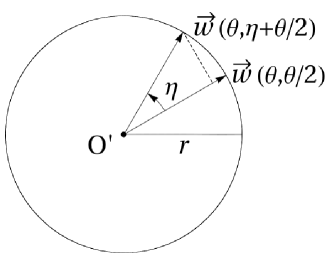
1.4 Rotating a polytope around a face
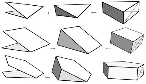
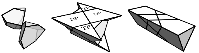
Let be an -polytope in canonically embedded in , and one of its facets (-dimensional faces). The convex hull of and its image by a rotation in of an angle less than and centered at is an -polytope, which will be denoted by , and will be called a polytope obtained from by rotating it around . It can be abstractly defined as
in other words it is obtained by crushing the facet of the product by the projection (see Figure 1)
Note that the boundary of consists of
For example, rotating a pentagon around a side, we get a polytope bounded by two pentagons, two triangles, and two quadrilaterals. In other words, it is obtained by crushing a rectangular face of the pentagonal prism. As is shown in Figure 1 (right), it looks like a dumpling, so it will be called a dumpling. This is called a gyoza in [CY, CYY]. In general, rotating an -gon around a side, we get a polytope bounded by two -gon’s, two triangles, and quadrilaterals; this polytope will also be called a (3-dimensional -) dumpling. A 3-dumpling is a tetrahedron, a 4-dumpling is a triangular prism.
High dimensional ones will be also called dumplings.
2 Veronese arrangements
A hyperplane arrangement in (or ) is said to be Veronese if under a suitable linear change of coordinates, is given by , where
Here are real numbers, and are coordinates on . Note that by proposition 3, if , every arrangement of hyperplanes in general position is Veronese.
Proposition 5
For the curve of degree defined by
the osculating hyperplane at the point is given by .
The curve is often called a Veronese embedding of into (or ). This is the reason for coining Veronese arrangements.
From here to the end of next section, we work in . The binomial theorem tells
so that if is even,
if is odd,
2.1 Chambers cut out by Veronese arrangements
The closure of each connected component of the complement of a hyperplane arrangement is called a chamber. Let a Veronese arrangement be given as in the previous section. Each chamber is given by a system of inequalities
which is often denoted by the sequence
Group action: Since the Veronese arrangement is determined by a sequence of points in arranged in this order, the shift
acts on the set of chambers by
The cyclic group generated by will be denoted by . Note that if the points are so arranged that the transformation is given by a projective one, then the corresponding action on is also projective. Thus we have the well-defined action on the set of chambers as above for any sequence .
2.2 A specific feature of Veronese arrangements
Let a Veronese arrangement of hyperplanes
in be given as in the previous section. If we let tends near to , the intersection pattern does not change, that is, there is no vertex (intersection point of hyperplanes in ) in the slit between the hyperplanes and . More precisely, the hyperplanes and divide the space into two parts, and one of them does not contain any vertex.
This fact gives the following information on the chambers cut out by . If a chamber in the slit between the hyperplanes and does not touch the intersection , then this chamber is the direct product of a chamber of the restricted arrangement and the unit interval. If a chamber in the slit touches the intersection of the two hyperplanes, then (since the hyperplanes are in general position) there is a chamber of the restricted arrangement with a facet included in and the chamber in the slit is the polyhedron obtained from by rotating around .
A polyhedron (of dimension greater than 1) is said to be irreducible if it is not a direct product of two polyhedron nor is obtained from a lower one by rotation described in §1.4. For example, triangles, rectangles, tetrahedra, prisms, cubes and dumplings are reducible, while pentagon is irreducible.
A combinatorial study on Veronese arrangements is made in [CY]. We do not use in this paper the result obtained there. To give a general idea, we just quote one of the results: Consider a Veronese arrangement of hyperplanes in .
-
•
If is odd, then every chamber is a direct product of the unit interval and a chamber of , or is obtained from a chamber of by rotating it around a facet.
-
•
If is even, then there is a unique irreducible chamber. Other chamber is obtained from like the above.
In this paper, for a Veronese arrangement of even dimension, the unique irreducible chamber will be called the central chamber.
3 Six planes in the 3-space
In this case there is no central chamber. The arrangement is Veronese. We are going to choose a particular arrangement so that the action of a group of orientation preserving projective transformations will be geometrically visible.
The elements of the group are given by matrices (up to scalar multiplication) with coefficients . The group is a subgroup of . Notice that is not a group since inverse operation is not always defined. However it is defined up to scalar matrix multiplication, so that the quotient has a group structure.
The group acts on the chambers with four orbits: prisms, tetrahedra, dumplings, cubes. The orbit of a prism together with a cube is a solid torus. The orbit of a dumpling is a second solid torus linked with the first one. The orbit of a tetrahedron is the complementary of the two solid tori. Actually, the union of one of these solid tori and the orbit of a tetrahedron is a solid torus as well.
3.1 Simple observations
3.1.1 Cutting a tetrahedron and a prism
Chambers in the plane bounded by five or less lines are
diangle, triangle, quadrilateral, and pentagon.
Chambers in the space bounded by four or less planes are dihedron, trihedron, tetrahedron; to see further we cut a tetrahedron by a plane. There are two ways to cut (see Figure 2).
If we denote a tetrahedron by , and a (triangular) prism by , then the two cuttings can be presented as
where (triangle) means and share a triangle.
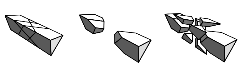
We cut next a prism. There are five ways to cut (see Figure 3).
If we denote a cube by , and a (pentagonal) dumpling by , then the five cuttings can be presented as
The last one will appear again in §4.3.4.
3.1.2 A few facts seen from the above cuttings
Since five planes cut out tetrahedra and prisms, if two chambers cut out by an arrangement of six planes are adjacent along a face, the union is a tetrahedron or a prism. Thus though and have quadrilateral faces, they are not face to face.
When two ’s are face to face along a pentagon, the remaining two pentagons do not share an edge. Since there is one pentagon on each plane (see Introduction), and since the group acts on the arrangement, we conclude that there are six ’s, which are glued to form a solid torus (see §3.4).
3.2 Setting
If we can choose coordinates on and the equations of hyperplanes so nicely that the -action is clearly seen, it would be nice. Though we can not expect this in general, when , there is a very good choice ([Mo] and remark after proposition 6). We work in the real projective space coordinatized by . Our six planes are
where
Note that if we put , then we have
Note also that if we change from to , the new arrangement is the mirror image of the original one.
We often work in the Euclidean 3-space coordinatized by
especially when we speak about distance and/or angle, without saying so explicitly.
3.2.1 A group action and a cubic curve
The six planes admit the transformations
which are of order 3, 2 and 2, respectively. These are given by the projective transformations
where . Note that . In the euclidean space, acts as the -rotation around the axis generated by the vector , and the -rotation about the axis generated by the vector . The transformation exchanges the plane
and the plane at infinity. They generate the orientation preserving projective transformation group
which is a subgroup of of order with center . The relations , and show that is also isomorphic to the dihedral group
Proposition 6
There is no invariant plane by . There are two orbits of order two,
where
There is no orbit of order three.
proof. If is invariant by , it is different from . If, in addition, it is invariant by it is orthogonal (in the euclidean space) to the vector . Such a plane is not invariant by , so that there is no plane invariant by .
Suppose now that belongs to an orbit of order , say , different from . The group acts necessarily trivially on a set of order so that . Then, as above, is orthogonal to the vector and is not invariant by so that . The equation of writes , and the one of writes . Writing that or , we find that .
Now, suppose that belongs to an orbit of order , then the order two elements and act trivially on this orbit, so that , and similarly for and . In particular and, since is a half-turn rotation about the vector , either is orthogonal to the vector or contains the line generated by the vector .
In the first case, is no longer orthogonal to the vector so that , and as well, must contain the line generated by the vector , so that , and then itself, is orthogonal to the vector . Therefore would be invariant, which is impossible.
In the second case, since is not invariant and then not orthogonal to the vector , the plane doesn’t contain the line generated by the vector , and therefore is orthogonal to the vector . We are brought back to the first case.
Each plane intersects the remaining five; they cut out a pentagon, five triangles and five rectangles. See Figures 5, and 4 for and , respectively.
The six planes form a Veronese arrangement in the order:
by which we mean, there is a unique rational cubic curve osculating these six planes in this order. Note that and respect the order, and just reverses the order. Proof goes as follows.
If the regular hexagon (the projective line coordinatized by ) is given by
(here, regular means there is a projective transformation sending to , to , …, to ) then the osculating curve is given by
which osculates the planes at
Remark. The chosen arrangement can be called selfadjoint in the following sense. The dual coordinates of the planes are
For instance the equation of the plane writes . The six planes turn out to be the points
in the dual space coordinatized by . They are on the cubic curve given by
in this order. Indeed we have
The planes supported by three consecutive points
happen to be the original ones:
We sometimes code these six planes as . Then the transformation of above induces a projective transformation of sending mod 6. This generates the cyclic group .
3.2.2 The twenty points
Convention: . Three planes meet at a point; there are of them. They are divided into three -orbits:
where . Note that the distances from the vertices to the origin are either
In the -coding, the three orbits above are represented by
respectively, where stands for .
3.2.3 An invariant quadratic form
While there are many -invariant quadratic forms in , if we ask the zero set passes through the six vertices marked and , then it is (up to scalar multiplication) given by
The surface and the curve do not meet: in fact, substituting the expression of the curve in into , we have .
By identifying the space and its dual, we regard the cubic curve live in our space, that is, the curve is defined by
Then this is the unique rational cubic curve passing through the six points marked and :
This curve is on the surface .
3.2.4 The twenty six chambers
The six planes in cut out
two cubes , twelve prisms , six tetrahedra , six dumplings .
3.2.5 The six planes
For the planes , the intersection with other planes are shown in Figure 4.
Here stand for If the plane , defined by , is coordinatized by , then the dotted curve is the conic (a hyperbola)
For the planes , the intersection with other planes are shown in Figure 5.
If the plane , defined by , is coordinatized by , then the dotted curve is the conic (hyperbola) , and the point is the point where the curve kisses the plane .
3.2.6 Bottom and top
It is convenient to consider the triangle with the three vertices in the plane as the ground floor, and the triangle with the three vertices in the plane at infinity as the ceiling. The planes are orthogonal to the ground. The intersection (lines) of the six planes with the floor and the ceiling are shown in Figure 6. The dotted curves are the intersections with the surface .
3.2.7 Octant chambers
The finite space coordinatized by
is divided by the three planes and into eight chambers. We denote them as
In this section, we see how these chambers are cut by the three planes and . In the chambers and , the happenings are similar, and in the remaining six chambers, similar things happen. Set
If we write these as , they permit the -action
In the chamber : There are four -orbits represented by
Here effective ones are marked by dots. For example, the last one is defined by and ; these three inequalities imply the other ones and . The number of dots corresponds to the number of walls.
As a whole, there are a cube and three and three (see Figure 8). One and another in the opposite chamber are glued along the plane at infinity forming a (full) prism (see Figure 7).
If we cut this chamber by a big sphere centered at the origin, the intersection with the chamber is surrounded by three arcs (), and the arc-triangle is cut by the three lines (). Around a triangle (cube), there are a triangle (), a pentagon (), a triangle (),… (see Figure 23 and Figure 24 left).
In the chamber : There are four -orbits represented by

In the chamber : This chamber does not admit the group action. Since and imply , and so , we have Among the remaining four, there is a unique compact one:
(See Figures 8(right) and 9(left).) The others are
and
One (resp. ) and another (resp. ) in the opposite chamber are glued along the plane at infinity forming a (full) dumpling (see Figure 9).
If we cut this chamber by a big sphere centered at the origin, the chamber is surrounded by three arcs (), and the arc-triangle is cut by the two lines (). There are a triangle (tetrahedron) and two quadrilaterals, which are sections of and (see Figure 23 and Figure 24 right).
In the chamber : Since and imply , and so , we have . Among the remaining four, there is a unique compact one:
The others are
and
3.3 The solid torus made of the two cubes and the twelve prisms
The two cubes kiss at the two vertices and , which are opposite vertices of each cube. Around the two cubes are twelve prisms, forming with the two cubes a solid torus. We explain how they are situated.
3.3.1 The two cubes and the six prisms around
The two cubes and the six prisms around , form in the finite (Euclidean) space an infinitely long triangular cylinder called the big-cylinder and bounded by . It is defined by the inequations (figure 10):
3.3.2 The small cylinder
Considering the planes and defined in proposition 6, we have where is the involution defined in 3.2.1. Let us denote by the heptahedron shown in figure 12 and defined by
We set . The faces of the heptahedron are three triangles, three pentagons and one hexagon. We consider the solid (called the small cylinder) given by the union of the two heptahedrons and the six prisms. It is homeomorphic to a triangular prism by a homeomorphism preserving the generating lines (see figure 13).
3.3.3 The prism torus
The -orbit of one of the six compact prisms around is given by twelve prisms, the six extra ones being located around . Now the image of the small cylinder by , or equivalently, the -orbit of one prism and the heptahedron , form the union of the big cylinder and the six prisms around . These two solid cylinders and are attached by along their bases and therefore form a solid torus. Let us call it the prism torus. Thus, this prism torus is decomposed into sixteenteen cells, four heptahedrons and twelve prisms, on which acts the group .
3.3.4 The boundary of the prism torus
The prism torus consists also of the two cubes and the twelve prisms. Note that this torus is a tubular neighborhood of the projective line joining and . Therefore, as mentioned in the introduction of section 3, the complementary of this torus is a solid torus as well.
The above construction shows that the boundary of the torus consists of the faces of the prisms on the lateral boundary on the small cylinder and their images by . In particular, no face of the cubes belongs to the boundary of the prism torus.
The boundary of the prism torus on each plane consists of two quadrilaterals and two triangles (see figure 13). They are shown more explicitly the pattern below:
The twelve quadrilaterals and the twelve triangles tessellate the boundary torus as below. To indicate the identification, four copies of the plane number 1 are shown in addition. After identification, there are
note that among the twenty vertices, only and are missing.
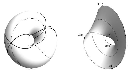
3.4 The solid torus made of the six dumplings
Each of the six dumplings is glued along the two pentagonal faces with two others. The six dumplings form a solid torus; let us call it the dumpling torus. This section is devoted to understand it.
3.4.1 A dumpling
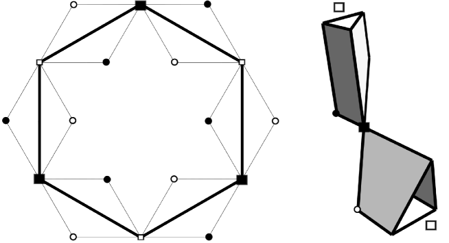
A dumpling has two rectangular faces, two triangular faces, and two pentagonal faces (see Figure 15), which share an edge with two vertices marked white and black squares. This edge will be called a special edge (see Figure 16).
Each dumpling is cut into two by the plane at infinity: the part with two vertices is denoted by , and the other by . They are shown in Figure 9.
3.4.2 The dumpling torus
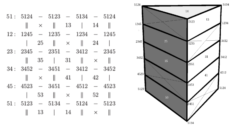
The six dumplings glued along their pentagonal faces form the dumpling torus. Figure 17 shows the six pentagons glued along the special edges forming a circle. In the figure, special edges are shown by thick segments.
Remember that the planes
and the curve lives inside the dumpling torus, and touches six pentagons in this order. In Figure 18, the six dumplings are glued along their pentagonal faces. The smallest pentagon on the top and the biggest one at the bottom are on the plane number 6; they should be identified after turn. The pentagon on the plane 2 is next to the top, and so on. The edges are labeled as 12, 23, …; for example, 12 indicates the intersection of two pentagons on the planes 1 and 2. The edges labeled by two consecutive numbers are the special edges. The special edges form a circle:
One can see in Figure 18, in front, the quadrilateral consisting of two triangles and two rectangles with edges labeled 12 at the top and 61 in the bottom, and segments 31, 41 and 51 are inside; this rectangle together with the pentagon is on the plane 1.
3.4.3 Some curves on the dumpling torus
Trace the edge 51 on this rectangle along non-special edges, and we have the close curve:
Trace the edge 41 on this rectangle along non-special edges, and we have the close curve:
The other edges form a single closed curve:
Boundary of a(ny) pentagon; they will be called later:
The diagonal of the front quadrilateral in Figure 18 connecting crossing the edges and ; this will be called later.
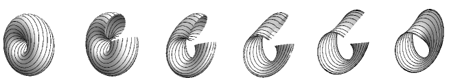
3.4.4 Another description of the dumpling torus
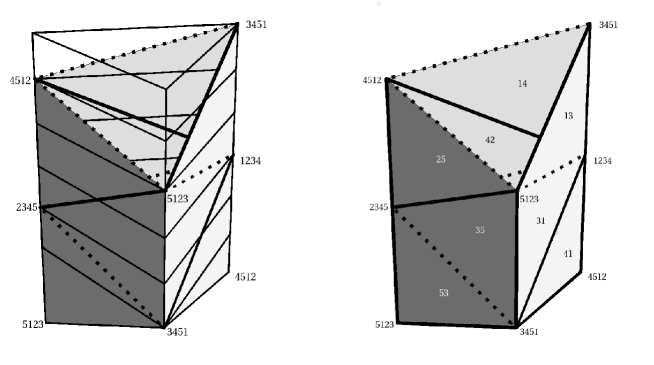
The dumpling torus presented as the pile of dumplings above can be understood also as follows, which may help the understanding: Consider the cylinder made by six copies of a pentagon times the interval , glued along pentagonal faces; the top and the bottom with twist. The side of the cylinder is tessellated by rectangular tiles. Now choose six squares diagonally arranged (thanks to the twist, one can make it consistently) and compress these squares vertically, then you end up with the pile of dumplings above. In Figure 19, it is shown in particular, how the dumpling with pentagonal faces 5 and 6 is made by a pentagon times the interval.
3.4.5 The boundary of the dumpling torus and the line
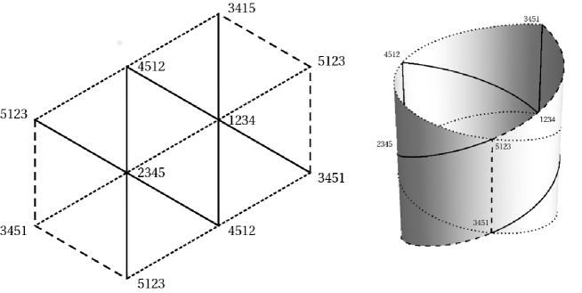
The boundary of the dumpling torus on each plane is shown in Figures 5 and 4, and more explicitly again in Figure 20. It consists of two quadrilaterals and two triangles . This is the front rectangle shown in Figure 18, and a column of Figure 19 left. We show it again below by a diagram which will fit the diagram of the boundary of the prism torus shown in §3.3.4.
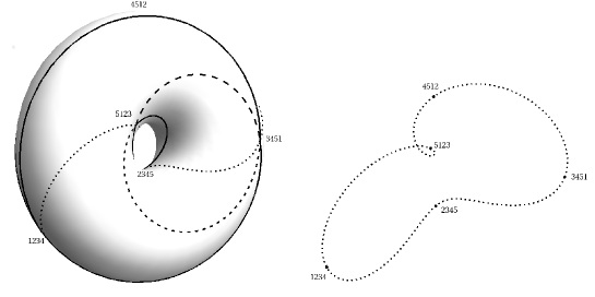
Note that in the left diagram, the two opposite stands for the same vertex; in the right diagram, two opposite stands for the same vertex. The diagonal joining two opposite in the left (in Figure 20 left, the line ) and the diagonal joining two opposite in the right (in Figure 20 right, a vertical line ) are closed curves, which are homotopically equivalent on the boundary of the dumpling torus; Let us call one of them .
We now show the six such forming the boundary of the dumpling torus. The twelve quadrilaterals and the twelve triangles tessellate the boundary torus as below. To indicate the identification, four copies of the plane number 1 are shown. After identification, there are
note that among the twenty vertices, only and are missing.
3.5 Tetrahedra
Let us compare the (tessellated) boundary of the prism torus and that of the dumpling torus. They share the quadrilateral faces. The two solid tori almost fill the space; six tetrahedra are the notches. Each tetrahedron has two triangular faces adjacent to prisms and other two triangular faces adjacent to dumplings:
In Figures 8(right) and 9(left), we see that each tetrahedron has bounded base (triangle ) on the big-cylinder, an infinitely long face on the prism torus, and two infinitely long faces on the dumpling torus; intersection of the last two faces is a special edge. The six tetrahedra form a rosary (see Figure 21(left) for a combinatorial idea).
The curve , introduced in §3.2.3 lives in the union of the six tetrahedra.
3.6 Intersection with a big sphere
The aim of this section is to visualize what happens near the plane at infinity by looking at the intersection with a big sphere.
The sphere at infinity is shown in Figure 22; the plane at infinity (see Figure 6) is obtained by identifying antipodal points. The three circles represent (the intersections with the planes) showing an octahedron, and the three lines represent (the intersections with the planes) . They cut out 24 triangles. Each triangle is a section of a prism or a dumpling. Dotted circles represent (the intersection with) the surface .
A very big sphere is shown in Figure 23. The three circles (showing an octahedron) and the three lines represent as in the previous figure. The triangle appeared at the center is the section of a cube; the other cube situates out of the picture. The six small triangles are the sections of the tetrahedra.
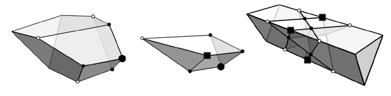
Each prism is the union of two parts and as is shown in Figure 7, glued along the shaded triangle. Now the shaded triangle is thickened; the sections of and with the big sphere are a triangle and a pentagon, respectively. (See Figure 24 left.)
Each dumpling is the union of two parts and as is shown in Figure 9, glued along the shaded triangle. Now the shaded triangle is thickened; the sections of and with the big sphere are both quadrangle. (See Figure 24 right.)
Intersection with the big sphere with the surface is shown in Figure 25; which shows that the surface does not path through any prisms nor cubes, and that the surface can be considered as an approximation of (the boundary of) the prism torus.
4 Seven hyperplanes in the 4-space
Seven hyperplanes in general position in cut out a unique chamber, bounded by the seven hyperplanes, stable under the action of the cyclic group ; let us call it the central chamber CC. This action can be projective if the hyperplanes are well-arranged. The intersection of CC and a hyperplane is a dumpling.
So the boundary of CC is a 3-sphere tessellated by seven dumplings. We would like to know how they are arranged, especially the -action on the tessellation. In [CY], the seven dumplings in is shown (see Figure LABEL:7facebody70), in which the -action can be hardly seen.
We first observe the tessellation. We label the dumplings as so that the dumplings and , modulo 7, share a pentagon, and the group action induces a transformation modulo 7. The special edges form a circle . (Recall that a dumpling is bounded by two pentagons, two triangles and two quadrilaterals, and that the intersection of the two pentagons is called the special edge.) If we remove seven pentagons from the 2-skeleton of the tessellation, it remains a Möbius strip with the curve as the boundary.
We find, in the 2-skeleton, a subskeleton homeomorphic to a disc which bound the curve . This implies that is unknotted, and that is twisted only by
We give another description of the tessellation so that the action of can be seen; we start from a vertical pentagonal prism, horizontally sliced into seven thinner prisms. We collapse vertically the seven rectangular faces diagonally situated on the boundary of the prism; this process changes each thinner prism into a dumpling. Identifying the top and the bottom after a suitable rotation, we get a solid torus made of seven dumplings, so that the solid torus admits a -action. Consider a usual solid torus in our space and put outside of ; the boundary of , which is also the boundary of , is a torus . We collapse by folding the torus into a Möbius strip, which can be identified with , whose boundary can be identified with . We will see that the result, say , of this collapsing is homeomorphic to . In this way, we recover the tessellation of by seven dumplings.
To make our idea and a possible inductive process clear, we start this chapter by studying a chamber bounded by five (as well as six) hyperplanes stable under the action of the cyclic group (resp. ); though such a chamber is not unique, the above statement with obvious modification is still true, if we understand the special edge of as . A 3-dumpling is a tetrahedron, and a 4-dumpling is a prism. After the collapsing process as above, we get the manifolds (resp. ). We prove in detail that is homeomorphic to ; for other cases proof is similar.
4.1 Five hyperplanes in the 4-space
Five hyperplanes in the projective 4-space cut out sixteen 4-simplices. If a hyperplane is at infinity, then the remaining four can be considered as the four coordinate hyperplanes, dividing the space into chambers. The boundary of each 4-simplex is of course made by five tetrahedra. In other words, five tetrahedra are glued together to make a (topological) 3-sphere: around a tetrahedron, glue four tetrahedra along their faces, and further use the valley of each pair of triangles in order to close the pair like a book.
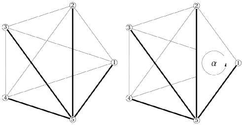
4.1.1 Labeling and a study of 2-skeleton
We study the above tessellation more precisely. Label the five hyperplanes as . Choose one 4-simplex, out of sixteen, and call it CC. We use the convention
The five vertices of CC are:
which are often denoted simply by
respectively. The boundary of CC is made by five tetrahedra:
(Tetrahedron has vertices .) Any two of them share a triangle:
there are ten of them. These tetrahedra tessellate the 3-sphere . We consider the sequence , in this order, and name the intersections of the two consecutive ones as:
(Note that the union of these five triangles form a Möbius strip, but for a while just forget it.) Remove these five triangles from the 2-skeleton of the tessellation. Then five triangles remain, forming another Möbius strip
Its boundary
is an unknotted circle because bounds also the disc
4.1.2 Visualization
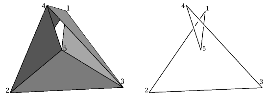
Since the situation is quite simple, we visualize the happenings. Consider a tetrahedron with vertices in our space, and put vertex 5 at the barycenter. The barycentric subdivision of this tetrahedron (which yields ) together with its complementary tetrahedron fills the 3-sphere. Figure 26 shows the 2-skeleton consisting of ten triangles as the union of the Möbius strips and the complementary one. You can find the disc, given in the previous subsection, bounded by the curve . When you make a paper model of the 2-skelton out of Figure 26, be ware that the two Möbius strips have different orientations.
4.1.3 From a solid torus
We would like to give another description, which will prepare the next step where the number of hyperplanes is , in such cases, naive description above would hardly work. We start with a vertical triangular prism, horizontally sliced into five thinner triangular prisms. Its top and the bottom triangles are identified after a rotation; this makes the vertical prism a solid torus. The boundary torus is tessellated by fifteen rectangles. Now collapse vertically five diagonal rectangles. This changes every remaining rectangles into triangles, and the thinner triangular prisms into tetrahedra. Further, use each collapsed edge as a valley of each pair of triangles face-to-face in order to close the pair like a book. This identification makes the solid torus a 3-sphere tessellated by five tetrahedra, recovering the tessellation described in §4.1.1.
A vertical triangular prism horizontally sliced. We show/repeat the above process by using the labels (they correspond the labels of the five hyperplanes ). Consider five triangles labeled by two consecutive numbers: (they correspond the triangle ). The triangle 51, for example, has three vertices with labels
(they correspond the points ). Now operate the group on the labels: mod 5, and we get four other triangles, for example, the triangle 12 has three vertices:
We make a triangular prism by putting the triangle 51 above the triangle 12; the two vertices of 51 having the same labels of the ones of 12 should be put just above each other. In a word this prism is the sandwich made by the two triangles 51 and 12.
In this way, we make five sandwiches and pile them to form a vertical triangular prism. The table in Figure 28 repeats what we described. Each off-diagonal rectangle is labeled by the two numbers common to the four vertices.
Collapsing rectangles. If we identify two points with the same indices as sets, for example, , you find five rectangles with pairwise coincide vertices (marked by ), situated diagonally. We collapse such rectangles vertically to a segment, each called a special edge. Note that a special edge has two ends which are labeled by consecutive numbers: Accordingly all the remaining rectangles become triangles and, the five thin prisms become tetrahedra. But as a whole it still remains to be a cylinder. This collapsing process is described in Figure 29. Here the prisms are hollow so that we can peep inside.
Identifying the top and the bottom to get a solid torus . We identify the top triangle and the bottom triangle of the collapsed vertical prism according to the labels; note that we must twist the triangle by . By the identification we get a solid torus, say ; its meridean is represented by the boundary of a(ny) triangle, in Figure 28, say 51 (or 12, 23,…). Note that it is still an abstract object. The five special edges now form a circle:
We take a vertical line, in Figure 28 (left), with a twist, say,
as a parallel.
The torus and the solid torus . We consider in our space () a usual (unknotted) solid torus, say , and put our solid torus fills outside of , so that the tessellated boundary torus
has par as the meridean, and mer as the parallel. From the description of the vertical prism, we see ten triangles tessellating the torus arranged in a hexagonal way (Figure 30-left).
Note that the triangulated torus above is not a simplicial complex; indeed there are two edges with the same vertices, for example, . Anyway, you can see the curve lies on the torus as a -curve (see Figure 31).
Collapsing the solid torus by folding . On the torus , there are pairs of triangles with the same vertices. We identify these triangles by folding the torus along the curve . This collapses the solid torus ; we prove below that the resulting space, say , is still .
The torus is folded to be a Möbius strip with boundary :
Note that is a simplicial complex. If we use complementary labeling, for example, for , this is exactly the same as we got several pages before. On the hexagonal expression of the torus , this folding is done as closing a book along the diagonal.
The process of collapsing the solid torus onto the Möbius strip can be explicited by the following homotopy parametrized by :
where
and parametrizes the solid torus (Figure 34).
Puffing the Möbius strip to make a torus. The inverse operation of folding the (unknotted) torus to the Möbius strip (with twist) can be described as follows: Consider a Möbius strip being double sheeted like a flat tire folded along . Then puff the tire to be a air-filled tire . It is illustrated in Figure 33 seen from right to left.
A disc bounding . Let us repeat the disc in §4.1.1 bounding , using complementary labeling:
Proof that is homeomorphic to . The collapsing of by folding along and collapsing on is nothing but the gluing of the set of the five tetrahedra tiling in such a way that the tetrahedra facets are identified by pairs. In doing so we must get back in one hand, and, on the other hand, the triangles of the boundary are identified by pairs to get the Möbius strip . The result , is a closed -dimensional manifold since the link of each vertex is homeomorphic to a -sphere, namely the -skeleton of a tetrahedron. For instance the link of the vertex is the union of the four triangles , where 15 for example, is the triangle with vertices and . The -manifold , as a continuous image of , is clearly connected.
Now, computing the fundamental group will prove that is simply connected and therefore, by Poincaré-Perelman theorem, homeomorphic to . Indeed, since is endowed with a structure of simplicial complex, is isomorphic to , where denotes the -skeleton. The group can be described by generators and relators as follows. Firstly, we observe that the -skeleton is the complete graph over the five vertices (using complementary labeling) (Figure 35).
Recall that we can use a maximal tree (that is a tree containing all vertices) to compute the fundamental group . Indeed, to each egde not contained in the tree, we associate in a obvious way a loop based at . The set of these loops is a basis of the free group . Therefore we see that is the free group over the six following generators (still using complementary labeling for the sequence of vertices and chosing as a base point):
Secondly, the relators of are associated with the ten facets coming from the five tetrahedra tiling :
4.2 Six hyperplanes in the 4-space
Six hyperplanes in the projective 4-space cut out six 4-simplices, fifteen prisms of type and ten prisms of type . If a hyperplane is at infinity, then the remaining five bound a simplex. Other chambers touch this simplex along 3-simplices (five ), along 2-simplices (ten ), along 1-simplices (ten ) and along 0-simplex (five ).
Though a prism of type is bounded by six hyperplanes, it does not admit an action of the group . So we consider one of the prisms of type , which is bounded by six prisms (of type ). We study how these six prisms tessellate a 3-sphere.
4.2.1 Labeling and a study of 2-skeleton
Let the six hyperplanes bound a chamber CC of type . The chamber CC has six faces , which form the -orbit of the prism
where . Note that the rectangular face of behind is , and the rectangular face in front below is . 111Using the notation introduced in Chapter 2, CC is represented by , and its boundary consistes of The boundary of consists of (cf. §LABEL:2D) The 2-skeleton of CC consists of six triangles and nine rectangles. Remove the intersections of the two consecutive ones:
(Note that the union of these six rectangles form a cylinder, not a Möbius strip.) Then the remaining six triangles and three rectangles form a Möbius strip
Möbius 6
Its boundary
is an unknotted circle because bounds also the disc
4.2.2 From a solid torus
We start with a vertical rectangular prism, horizontally sliced into six thinner rectangular prisms. Its top and the bottom rectangles are identified after a rotation; this makes the vertical prism a solid torus. The boundary torus is tessellated by 24 rectangles. Now collapse vertically six diagonal rectangles. This changes eighteen rectangles (out of 24) into six segments (forming a circle) and twelve triangles. Accordingly, the six thinner rectangular prisms (actually cubes) into prisms. Next use each collapsed edge as a valley of each pair of triangles face-to-face in order to close the pair like a book, and further identify three pairs of rectangles. This identification changes the solid torus into a 3-sphere tessellated by six prisms.
A vertical rectangular prism horizontally sliced. We show/repeat the above process by using the labels (they correspond the labels of the six hyperplanes ). Consider six rectangles labeled by two consecutive numbers: (they correspond the rectangle ). The rectangle 61, for example, has four vertices with labels
(they correspond the points ). Now operate the group on the labels: mod 6, and we get five other rectangles, for example, the rectangle 12 has three vertices:
We make a rectangular prism by putting the rectangle 61 above the rectangle 12; the two vertices of 61 having the same labels of the ones of 12 should be put just above each other. In a word this prism is the sandwich made by the two rectangles 61 and 12.
In this way, we make six sandwiches and pile them to form a vertical rectangular prism. The following table repeats what we described. Each off-diagonal rectangle is labeled by the two numbers common to the four vertices.
Table of piles 6
Collapsing rectangles. If we identify two points with the same consecutive indices as sets, for exmaple, but , you find six rectangles with pairwise coincide vertices (marked by ), situated diagonally. We collapse such rectangles vertically to a segment, each called a special edge. Note that a special edge has two ends which are labeled by consecutive numbers: Accordingly the remaining rectangles next to the special edges become triangles, and the six thin rectangular prisms become triangular prisms (). But as a whole it still remains to be a cylinder.
Identifying the top and the bottom to get a solid torus . We identify the top rectangle and the bottom rectangle of the collapsed vertical prism according to the labels; note that we must twist the triangle by . By the identification we get a solid torus, say ; its meridean is represented by the boundary of a(ny) rectangle, in Table of piles 6, say 61 (or 12, 23,…). Note that it is still an abstract object. The six special edges now form a circle:
We take a vertical line, in Table of piles 6, with a twist, say,
as a parallel.
The torus and the solid torus . We consider in our space () a usual (unknotted) solid torus, say , and think our solid torus fills outside of , so that the tessellated boundary torus
has par as the meridean, and mer as the parallel. From the description of the vertical prism, we see twelve triangles and six rectangles tessellating the torus arranged in a hexagonal way (identify the opposite sides of the hexagon):
Torus (hexagon) 6
Collapsing the solid torus by folding . We identify two vertices with the same indices as sets. Along each collapsed edge (special edge), there are two triangles with the same vertices; these triangles are folded along the special edge into one triangle. Further there are three pairs of rectangles with the same vertices; they are also identified. Consequently the torus is folded along the curve to be a Möbius strip, which turns out to be the same as the one in the previous subsection (shown as Möbius 6). In this way, we get a space from the solid torus made by six prisms by folding the torus (collapsing ).
Since the curve is unknotted, this folding is done exactly the same as in the previous section. Then is homeomorphic to .
A model. Put three vertices with labels without numeral 6: inside the prism . The Möbius strip above is shown in Figure 37 ([CYY]). From this picture, one can hardly see the action.
4.2.3
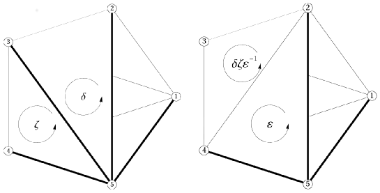
If we remove the sixth hyperplane, then the remaining five hyperplanes bounds a 4-simplex. This process can be described as follows: the prism on the sixth plane reduces to a segment. More precisely, the two triangles of the boundary of the sixth prism reduce to two points, and the prism reduces to a segment connecting these two points. Combinatorial explanation: The prism on the sixth plane with vertices
reduces () to the segment
Note that
Accordingly the other prisms reduce to tetrahedra, for example:
Remark. Consider an -gon in the plane bounded by lines. If you remove the -th line, then you get an -gon. During this process, the sides away from the -th sides do not change. Consider an -hedron in the 3-space bounded by planes. If you remove the -th plane, you get an -hedron. During this process, faces away from the -th face remain unchanged. In the present case, all the prism-faces change into tetrahedra.
4.2.4
If we add the sixth hyperplane to the five hyperplanes, then among the sixteen 4-simplices , some are untouched, some are divided into and (with section ), and some are divided into and (with section .) We will describe the change of into via that of these boundaries: the 3-sphere tessellated by five tetrahedra into that tessellated by six prisms.
As a preparation, we would like to explain this cutting process by using a 1-dimension less model: we truncate a vertex of a polyhedron in 3-space. Let us consider a polyhedron in the 3-space, say for example a tetrahedron bounded by four faces , and cut the vertex by the new plane named 4. The tetrahedron is truncated and is divided into a prism and a small tetrahedron; they share a triangle which should be called 4. Instead of describing this process by 3-dimensional pictures, we express it by 2-dimensional pictures describing the change near the vertex : the plane is divided into three chambers (imagine the letter Y) sharing a unique point representing the vertex 123, which we call the center. The cutting is expressed by a blowing-up at the center, which means inserting a triangle in place of the center point (see Figure 38, first line). Though this is not so honest as 3-dimensional pictures, this is still a fairly honest way to describe the cutting process.
There is a way to make these pictures simpler without loosing any information: We watch only one chamber, say 3, and show the cutting/blowing-up of the center only in the chamber 3 (see Figure 38, second line, right). You see that the terminal figure of marked triangle tells everything.
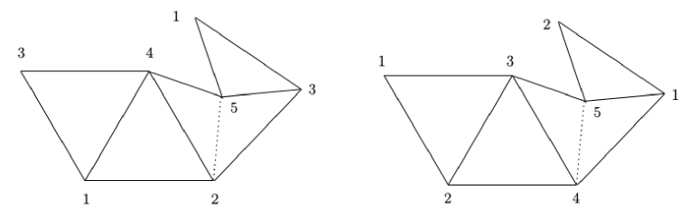
Now we are ready. Label the tetrahedra as as in the previous subsection. We choose the edge joining two vertices 1235 and 1345. Along this edge , there are three tetrahedra and 5. Other than these three, tetrahedron 2 touches the vertex 1235, and tetrahedron 4 touches the vertex 1345. We cut the edge by a new hyperplane 6. The tetrahedron 2 (resp. 4) has vertex 1235 (resp. 1345) as the intersection with ; this versex is cut, and the tetrahedron 2 becomes a prism (see Figure 39).
The tetrahedron 5 (as well as 1 and 3) has the edge ; this edge is cut, and the tetrahedron 5 becomes a prism (see Figures 40 and 3).
The new face 6 is a prism bounded by two triangles labeled 2 and 4, and three rectangles labeled 1, 3 and 5. Recall the above 1-dimension lower process, then the blow-up of the edge to become the prism 6 can be summerized by Figure 41.
In the case of seven or more hyperplanes, we describe the cutting/blow-up process only by this kind of figure.
4.3 Seven hyperplanes in the 4-space
Seven hyperplanes in the projective 4-space cut out a unique chamber CC stable under the action of . It is bounded by the seven dumplings. We study how the seven dumplings tessellate a 3-sphere.
4.3.1 Labeling and a study of 2-skeleton
The central chamber CC has seven faces , which form the -orbit of the dumpling
Note that the pentagonal face of behind is and the pentagon in front is . 222Using the notation introduced in [CY], CC is represented by , and its boundary consistes of The boundary of consists of The 2-skeleton of CC consists of seven pentagons, seven triangles and seven rectangles. Remove the intersections of the two consecutive ones:
(Note that the union of these seven pentagons form a Möbius strip, but for a while just forget it.) Then the remaining seven triangles and seven rectangles form a Möbius strip
Möbius 7
Its boundary
is an unknotted circle because bounds also the disc
4.3.2 From a solid torus
We start with a vertical pentagonal prism, horizontally sliced into seven thinner pentagonal prisms. Its top and the bottom pentagons are identified after a rotation; this makes the vertical prism a solid torus with a tessellation of the lateral boundary into 35 rectangles. Now collapse vertically seven diagonal rectangles. This changes 21 rectangles (out of 35) into seven segments (forming a circle) and fourteen triangles. Accordingly, the seven thinner pentagonal prisms into dumplings. Next use each collapsed edge as a valley of each pair of triangles face-to-face in order to close the pair like a book, and further identify seven pairs of rectangles. This identification changes the solid torus into a sphere tessellated by seven dumplings.
A vertical pentagonal prism horizontally sliced. We show the above process by using the labels of the seven hyperplanes. The boundary of the vertical pentagonal prism; each line, say is a pentagon on the plane . Two pentagons and sandwich a thin pentagonal prism. is the point .
Table of piles 7
Collapsing rectangles. If we identify two points with the same consecutive indices as sets, for exmaple, but , you find seven rectangles with pairwise coincide vertices (marked by ), situated diagonally. We collapse such rectangles vertically to a segment, each called a special edge. Note that a special edge has two ends which are labeled by consecutive numbers: Accordingly the remaining rectangles next to the special edges become triangles, and the seven thin rectangular prisms become dumplings. But as a whole it still remains to be a cylinder.
Identifying the top and the bottom to get a solid torus . We identify the top pentagon and the bottom pentagon of the collapsed vertical prism according to the labels; note that we must twist the triangle by . By the identification we get a solid torus, say ; its meridean is represented by the boundary of a(ny) pentagon, in Table of piles 7, say 71 (or 12, 23,…). Note that it is still an abstract object. The seven special edges now form a circle:
We take a vertical line, in Table of piles 7, with a twist, say,
as a parallel.
The torus and the solid torus . We consider in our space () a usual (unknotted) solid torus, say , and think our solid torus fills outside of . Let us see the boundary torus
has par as the meridean, and mer as the parallel. From the description of the vertical prism, we see fourteen triangles and fourteen rectangles tessellating the torus arranged in a hexagonal way (identify the opposite sides of the hexagon):
Torus (hexagon) 7
Collapsing the solid torus by folding . We identify two vertices with the same indices as sets. Along each collapsed edge (special edge), there are two triangles with the same vertices; these triangles are folded along the special edge into one triangle. Further there are seven pairs of rectangles with the same vertices; they are also identified. Consequently the torus is folded along the curve to be a Möbius strip, which turns out to be the same as the one in the previous subsection (shown as Möbius 7). In this way, we get a space from the solid torus made by six prisms by folding the torus (collapsing ).
Since the curve is unknotted, this folding is done exactly the same as in the previous section. Then is homeomorphic to .
A model. In [CY], the tessellation is shown, as we quote in Figure 42. In the figure, 0 stands for 7, and the edge connecting and is not drawn to avoid complication. Six dumplings are shown; they are packed in a dumpling. The other one is infinitely large. From this diagram, one can hardly see the action. To understand this group action is the motivation of our prism-collapse construction.
4.3.3
If we remove the seventh hyperplane, then the remaining six hyperplanes bounds a hyperhexahedron. This process can be described as follows: the dumpling on the seventh plane reduces to the union of two adjacent segments. More precisely, the two triangles of the boundary of the dumpling reduce to two points, the segment joining the remaining two vertices to a point, and the dumpling to the union of two segments joining the last one to the former ones. Combinatorial explanation: The dumpling on the seventh plane with vertices
reduces to the union of two segments
Note that
Accordingly the other dumplings reduce to prisms (cf. Figure 3), for example,
4.3.4
Let us describe the change of 3-sphere tessellated by six prisms into that by seven dumplings. As we explained in §4.2.4, we express this change – blowing-up a connected union of two edges (of a prism) – by cutting a prism 6 by a hyperplane 7 and dividing the prism into two dumplings, which share the pentagonal face that should be called 6. (See Figure 43).
4.4 hyperplanes in the 4-space
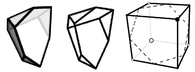
A Veronese arrangement of hyperplanes in the projective 4-space cut out a unique chamber CC, stable under the action of . It is bounded by -dumplings. (An -dumpling is bounded by two -gons, two triangles and rectangles.) The reader is expected to imagine how these -dumplings tessellate a 3-sphere. Here we show a 6-dumpling ():
The central chamber CC has faces , on which acts as mod . The 2-skeleton of CC consists of -gons, triangles and rectangles. Remove the intersections of the two consecutive ones:
Then the remaining triangles and rectangles form a Möbius strip , which the reader can make following the previous sections.
Its boundary
is an unknotted circle because bounds also a disc. To find a disc is not so obvious so we give a hint when (the reader is expected to guess the codes for , and then to guess what happens when )
(Answer: .)
4.4.1 From a solid torus
You start with a vertical -gonal prism, horizontally sliced into thinner -gonal prisms. Its top and the bottom triangles are identified after a rotation. This makes the vertical prism a solid torus; the boundary is tessellated by rectangles.
Now collapse vertically diagonal rectangles. This changes rectangles into segments (special edges) and triangles. Accordingly, the thinner pentagonal prisms deform into -dumplings, forming a solid torus . The special edges make a circle .
We consider in our space () a usual solid torus, say , and think our solid torus fills outside of .
In the tessellation on the boundary torus
each special edge is shared by the two triangles with the same code. The special edge is used as a valley to close the pair of triangles like a book, and further identify pairs of the rectangles. This identification changes the torus into the Möbius strip with boundary , and accordingly collapse the solid torus , and changes the solid torus into a 3-sphere tessellated by -dumplings, recovering the tessellation on .
4.4.2 From hyperplanes to hyperplanes
Consider the central chamber bounded by hyperplanes. If we remove the -th hyperplane, then hyperplanes bound the central chamber bounded by hyperplanes. This process can be described as follows: the -dumpling on the -th plane reduces to connected segments. Combinatorial explanation: The -dumpling on the -th plane with vertices
reduces to the union of segments
Accordingly, the other -dumplings reduce to -dumplings.
4.4.3 From hyperplanes to hyperplanes
Let us describe the change of 3-sphere tessellated by -dumplings into that by -dumplings. As we explained in §4.2.4, we express this change – blowing-up a connected union of edges (of a -dumpling) – by cutting the -dumpling (labeled by ) by the hyperplane (labeled by ) and dividing the -dumpling into two -dumplings, which share the -gonal face which should be labeled by . (See Figure 44).
5 Appendix: Higher dimensional cases
We describe higher dimensional dumplings for odd , and central chambers CCn for even in arrangements of hyperplanes in . Description will be just combinatorial. We start from dimension 0: 0-dimensional central chamber CC0 is a point.
5.1 Review
- D1: 1-dimensional dumpling is a segment, whose boundary consists of two CC0’s.
- CC2: The 2-dimensional central chamber CC2 (usually called a pentagon) is bounded by five ’s. Each share CC0-faces with two ’s.
- D3: Consider the direct product of CC2 and an interval . Choose a boundary component of CC2, and call it . Push down to , to get a dumpling . The crashed is called the special edge of . Accordingly, for a boundary component adjacent to (there are two of them), the rectangle is pushed to become a triangle. For a boundary component non-adjacent to (there are two of them), the rectangle leaves as it is. Thus the boundary of a dumpling consists of two CC2’s and two triangles and two quadrilaterals (The following notation is explained in [CY]):
- CC4: The 4-dimensional central chamber CC4 is bounded by seven ’s. Each shares CC2-faces with two ’s. The 2-skeleton of the -tessellation of minus the seven CC2’s form a Möbius strip with boundary consisting of seven special edges ’s of seven ’s.
On the other hand, we start with a vertical prism with base CC2, horizontally sliced into seven thinner prisms with base CC2. Collapse the seven diagonal ’s on the boundary into seven ’s; this makes each thinner prism a with the said as special one. Identify the top and the bottom CC2 after rotation so that the seven special edges form a circle . In this way, we get a solid torus made of seven ’s.
The (tessellated) boundary torus of is just the double of the (tessellated) Möbius strip branching along .
Fold the boundary torus along the curve to , Then the solid torus changes into the tessellated boundary of CC4.
5.2
- D2k-1: Consider the direct product of CC2k-2 and an interval . Choose a boundary component of CC2k-2, and call it . Push down to , to get a dumpling . The resulting is called the special edge of .
- CC2k: The -dimensional central chamber CC2k is bounded by dumplings . Each shares CC2k-2-faces with two ’s. The ()-skeleton of the -tessellation of minus the chambers CC2k-2 form a CW-complex with boundary ) consisting of special edges of dumplings .
On the other hand, we start with a vertical prism with base CC2k-2, horizontally sliced into thinner prisms with base CC2k-2. Collapse the diagonal on the boundary into dumplings ; this makes each thinner prism a dumpling with the said as special edge. Identify the top and the bottom CC2k-2 after rotation so that the special edges form . In this way, we get a solid torus made of dumplings .
The (tessellated) boundary torus of can be folded along the solid ()-torus (as a hinge) to . Then the solid torus changes into the tessellated boundary of CC2k.
Acknowledgement: The last author is grateful to K. Cho for his help. This collaboration started on 11 March 2011 , the very day of the Fukushima disaster in Japan.
References
- [CY] K. Cho and M. Yoshida, Veronese arrangements of hyperplanes in real projective spaces, Internat J of Math. 23(2012), 1–16.
- [CYY] K. Cho, K. Yada and M. Yoshida, Six points/planes in the 3-space, Kumamoto J of Math. 25(2012), 17–52.
- [Mo] B. Morin, Schwannengesang, 2012.
Francois Apéry
Université de Haute-Alsace
2, rue des Frères Lumière
68093 Mulhouse Cedex
France
francois.apery@uha.fr
Bernard Morin
villa Beausoleil
32, avenue de la Résistance
92370 Chaville
France
Masaaki Yoshida
Kyushu University
Nishi-ku, Fukuoka 819-0395
Japan
myoshida@math.kyushu-u.ac.jp