Complex Faraday and Kerr Rotations in Right and Left Handed Films
Abstract
By studying the rotations of the polarization of light propagating in right and left handed films, with emphasis on the transmission (Faraday effect) and reflections (Kerr effect) of light and through the use of complex values representing the rotations, it can be shown that the real portions of the complex angle of Faraday and Kerr rotations are odd functions with respect to the refractive index n and that the respective imaginary portions of the angles are an even function of n. Multiple reflections within the medium lead to the maximums of the real portions of Faraday and Kerr effects to not coincide with zero ellipticity. It will also be shown that in the thin film case with left handed materials there are large resonant enhancements of the reflected Kerr angle that could be obtained experimentally.
I Introduction
Negative refractive index magneto optical metamaterials (also called left handed materials (LHM)) are a new type of artificial material characterized by having both permittivity and permeability negative VE68 ; SM00 ; NIMM . Despite the fact that even with and , these metamaterials do have negative refractive index (). LHM have multiple uses: they may be used to resolve images beyond the diffraction limit PE00 ; SM04 , act as an electromagnetic cloaks for particular frequencies of light L2006 ; S2006 ; MMCLOAK , enhance the quantum interference Y or yield to slow light propagation P . The presence of negative indices of refraction in one-dimensional (1D) disordered metamaterials strongly suppresses Anderson localization, due to the lack of phase accumulation during wave propagation which thus weakens interference effects necessary for localization AS07 . As a consequence, an unusual behavior of the localization length at long-wavelengths has been observed AS07 ; BA12 ; G15 . This is unlike the well-known quadratic asymptotic behavior for standard isotropic layers (see, e.g. T13 ). It can be seen that the metamaterial configurations have an affect on the magneto-optical transport properties of the electromagnetic waves.
Particularly, the sign of plane polarization rotation angle in a left handed medium (LHM) is opposite to the sign of rotation angle in a right handed medium (RHM). The Faraday and Kerr rotations (FR & KR) are non-reciprocal polarization rotation effects in that the sign of the rotation is always relative to the direction of the magnetic field. This is different in optically active media rotate where the rotation of the polarization is relative to the direction of the wave vector. Thus, the non-reciprocity of the Faraday and Kerr effects allow light to accumulate rotations of the same sign and magnitude for both forward and backward propagation and can be enhanced even further by additional round-trip reflections through the medium.
If we assume no absorption and neglect the influence of the boundaries of the system, then in bulk materials the Faraday rotation angle is at a maximum for a given , , Verdet constant, and length of medium L that light travels within the medium for a constant linear magnetic field. When the reflection within the boundaries is important, the outgoing reflected wave is generally elliptically polarized even without absorption, where the major axis of the ellipse is rotated with respect to the original direction of polarization and the maximum FR (KR) angle does not necessarily coincide with angular frequencies of light at which zero ellipticity can be measured (we will come back to this question in section II).
The real part of the rotation angle describes the change of polarization in linearly polarized light. The imaginary part describes the ellipticity of transmitted or reflected light. Once we know the scattering matrix elements and of a one-dimensional light propagation problem, then the two characteristic parameters of Faraday/Kerr rotation (Real) and Faraday/Kerr ellipticity (Imaginary) of the magneto-optical transmission/reflection measurements can be written in complex form as the real and imaginary parts of a well-defined complex angle and (see Eqs. (6) and (19).
In the present paper, we theoretically consider the Faraday rotation of light passing through a RHM/LHM film of thickness L taking into account the multiple reflections from the boundaries. This exactly solvable simple model is chosen on purpose to present different aspects of RHM and LHM. It will be shown that the real part of the complex angle of Faraday rotation is an odd function with respect to the refractive index n, while the imaginary part of the angle is an even function of n. We have obtained the rotation angle of backscattered light (Kerr effect) from the RHM/LHM film as well. In the limit of ultra thin LHM film under specific circumstances we will see a large resonant enhancement of the reflected KR angle.
The work is organized as follows. In section II we formulate the problem with appropriate analytical expressions for the complex Faraday angle of transmitted light. In section III we analyze the Kerr effect and calculate the real and imaginary angles of reflection.
II Right handed and Left handed dielectric slab
Let us consider a slab: confined to the segment , with a positive surface impedance for either RHM or LHM, and characterized by permittivity and permeability . Both n and z, and therefore and , are frequency dependent complex functions that satisfy certain requirements based on causality. For passive materials, Re(z) and Im(n) must be greater than zero.
The two semi-infinite media outside of the slab are the same and are characterized by the dielectric constant . A linearly polarized electromagnetic plane wave with angular frequency enters the slab from the left at normal incidence. We take the direction of propagation as the x axis, and that of the electric field in the incident wave as the z axis. A weak magnetic field , is applied in the x direction and confined to the slab which causes the direction of linear polarization to rotate as light propagates through the medium. As a consequence, the dielectric tensor develops non-zero off-diagonal elements. Magneto-optic effects are related to the off-diagonal component () , whereas optical properties are related to the diagonal component . The magnitude of the off-diagonal component is two orders of magnitude smaller than that of the diagonal component . The generalized principle of symmetry of kinetic coefficinets implies that . The condition that absorption is absent requires that the tensor should be Hermitian : the diagonal components of the dielectric tensor are even functions of an applied magnetic field, and the off-diagonal components are odd functions and have first-order magnetic field dependence. The dielectric tensor of the slab is given by LL
| (1) |
where is the gyration vector directed on the magnetic-field direction. We absorb the external magnetic field into the gyrotropic vector for our to make our calculations valid for the cases of external magnetic fields and magneto-optic materials.
The components and , and in the film are not constant, where these values depend only upon the coordinate x. As well, when a magnetic field is applied in the x -direction, the off-diagonal elements cause coupling between the and electric field ( and ) components. The linearly polarized incident electromagnetic wave now can be presented as the sum of circularly polarized waves with opposite directions of rotation, which propagate through the slab with a different wave vector . For circularly polarized waves the Maxwell equations have the form LL :
| (2) |
where .
The reflectance and transmittance amplitudes can be obtained using the continuity of the tangential components of the electric (magnetic) fields at the two interfaces, and . Solving the equations with the appropriate boundary conditions at and we obtain for the transmitted waves and
where is the transmission amplitude for right and left circularly polarized light and can be presented in the form LL :
| (3) |
The coefficient of transmission and the phase are given by the following expressions, respectively
| (4) |
| (5) |
It can been proven very generally that there is a linear relation between the real and imaginary parts of or between and . These well known linear Kramers-Kronig relations can be rewritten in terms of localization length and density of states thou . The complex FR angle with the imaginary and real parts is introduced (see, e.g., 1995 )
| (6) |
As is seen from Eq. (6), if , then would be real; this signifies that the wave remains linearly polarized with vector rotated through the angle to the initial direction. In the Faraday geometry, or when a magnetic field is applied parallel to the direction of light propagation, and in the absence of material losses within a thin film (, where R is the reflection coefficient), if: (i) the sample is infinite (no boundaries), (ii) for certain thicknesses total transmission occurs, that is and (iii) The third condition implies that at a certain thicknesses becomes zero (the solutions of the following transcendental equation, ). At these points the transmission coefficient T, in contrast to the two previous cases, is not one and its value decreases with increasing with a saturated value of for tends . This saturated value corresponds exactly to one-quarter wavelength. In the case of a more complex geometry (for example a multi-layered periodic structure in an external magnetic field) it is possible for the Faraday rotation to be real more than three times with a simultaneously zero imaginary portion. If , the light has an elliptical polarization and is not simply linearly polarized. The ratio of the ellipses semi-axis is determined by relation ()
| (7) |
and with an angle between the large axis of the ellipse and the axis, as
| (8) |
For bulk (isotropic) samples or optical devices, where one-way light propagation is important, (see Eq. (5) when ) the result reads
| (9) |
Increasing of the linear polarizations rotation in a small length scale can be done in many different ways: (i) by taking into account the multiple reflections which in a finite layer or in resonant structures can lead to an enhancement of the FR angle in comparison with a single direct pass (for example Fabry-Perot cavities filled with a magneto-optic material FP ), (ii) tuning the optical properties of permittivity , and by the modification of the structure size and shape of the material; varying the composition of alloyed and intermetallic nanostructures. (iii) using metamaterials to tailor the optical properties of the host system met1 (iv) change the dielectric permittivity tensor of a medium with time, etc. The time dependence case may concern both to diagonal and non-diagonal permittivity terms of (see Eq. (1)).
In Ref. met1 the permittivity tensor of a magneto-optical material is tailored by embedded wire meshes. These wires can only tune the diagonal element of the permittivity tensor in terms of topological parameters and material properties and thus, effectively reducing to the value of (creating a near zero epsilon (NZE) metamaterial) NZE . For such frequencies the second term of Eq. (9) becomes zero and in the magneto-optical metamaterial can be enhanced by almost an order met1 . As for the Faraday rotation with time dependent dielectric permittivity tensor, where and is the angular frequency of the gyrotropic vector, it can be shown that the time dependent Faraday rotational angle, besides the standard term (9), contains an extra term which is proportional to time and which increases faster than the stationary term and becomes dominant provided that 1995 .
II.1 Real part of FR in RHM/LHM: Transmission
Let us first consider the FR for transmission from a slab. Since the Faraday effect is typically very small the effective incident indices of refraction and impedance for the two circular polarizations in the first order of g can be presented in the form
where (refractive index of a homogeneous material) and (impedance of a homogeneous material) are calculated when gyration vector is zero. Note, that by replacing we can use the above expressions for LHM.
One can simplify the analysis of and by expanding around the and of the slab in the absence of the magnetic field . Then the Taylor series of and in the neighborhood of & becomes:
| (10) |
| (11) |
Hence,
| (12) |
Evaluating the derivatives and at from Eq.(5) and substituting these expressions into Eq. (12) where, for convenience, we have introduced the new parameter , we get
| (13) |
Eq. (13) is a general expression and valid for any continuous material with arbitrary parameters , and . As expected, is odd in , where in LHM it will change sign of . Below we analyze a few of the limits for these parameters:
When tends to zero () , the above equation reduces to
| (14) |
which coincides with the RHM () thin-film result of Ref. zh .
If , i.e. when light propagates in a homogenous medium, we get
| (15) |
which coincides with the result of Refs. LL ; zh in the thick film limit where , if for RHM (the range of all optical frequencies). At the points , where the ellipticity is zero when , as was mentioned previously, and we get for the real part of FR
| (16) |
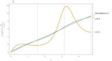
In Fig. 1, we show the FR angle of transmission vs for RHM, for three different values of surface impedance, using Eq. (13): , , and bulk material with no reflections where (dashed line). The angle steadily increases and oscillates around the line (Where is in units ) with certain periodicity of or on the scale . The oscillations in are due to interference effects in the plane-parallel slab and the amplitude of the oscillating part depends on . At we have for FR angle and for () . We were not able to find a closed-form solution analytically for the maximum of , and Eq. (13) and could not calculate the maximum increase of FR angle. However, for the estimated increase we used points , because the maximum value of for each period of oscillation is located very close to that point (see Fig. 1 where the vertical grid line appears). Then the ratio of at to the in a homogeneous media, Eq. (15), reads . For materials with relative impedance (semiconductor with zero extinction coefficient in the near or mid infrared range like tellurium or aluminum gallium arsenide) the ratio is almost 2. In otherwords, multiple reflections increase the overall time the light spends within the system showing an increase in Faraday rotation (1995, ). A similar increase of Faraday rotation was also found in SPIE ; met1 . However, for the composite system (dielectric with metamaterials or super lattice systems) the effective can be reduced up to and the ratio can thus be increased by an order or greater.
II.2 Imaginary part of FR in RHM/LHM: Transmission
Expanding around the and of the slab in the absence of the magnetic field (see Eq. (10)) and using the Taylor series for centered at we can similarly derive the expression for the for the imaginary portion of Faraday rotation as
| (17) |
This is again a general expression and valid for the arbitrary parameters , and . As expected, is even in , and when tends to zero. As it was previously mentioned, becomes 0 at z=1 (no boundaries), at (complete transmission) and at In the two former cases the coefficient of transmission becomes 1 when an external magnetic field is zero. The third case is very different: The transmission coefficient is not 1 and as tends . This saturated value corresponds exactly to one-quarter wavelength.
Note, that in the limit of a small magnetic field , the expression for , Eq. (7), coincides with , that is with Eq. (17).
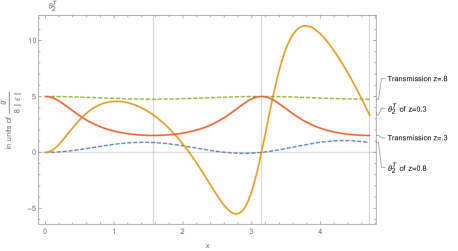
Fig. 2 shows for (solid) and (dashed) the imaginary angles of the FR, Eq. (17), for a RHM () versus . in the interval increases with , reaches a peak value and then drops to become minimum at some point. This pattern repeats as increases.
III Real and Imaginary parts of KR in RHM/LHM: Reflection
When linearly polarized light is reflected from the surface of a magnetized material, the direction of polarization is changed and the light is elliptically polarized. This is the Kerr effect and it is very similar to the Faraday effect except that the Kerr effect refers to the reflection and the Faraday effect refers to the transmission.
Before entering into a more detailed analysis of the complex Kerr effect, let us note that if we ignore the losses then there are some useful results which relate the and which follow already from the general expressions of the scattering matrix elements in terms of the transmission and reflection probabilities and the scattering phases and . Here is the total phase accumulated in a transmission event and are the phases accumulated by a particle which is incident from either face of the material (left or right) which is reflected. The scattering-matrix elements can be written in the form
For a spatially symmetric barrier the phase asymmetry vanishes and one has additionally
And it is clear that for any symmetric structure with no material loses, including the slab we are discussing,
Whereas previously it had been desribed that was the transmission amplitude of the wave, we shall now describe as the reflection amplitude. It can be shown for the slab that the reflection amplitude is given by LL ,
| (18) |
where is defined by Eq. (3).
Using a similar expression for Kerr effects complex reflection angle
| (19) |
where,
| (20) |
where is defined by Eq.(17).
When tends to zero (the thin film approximation), the above expression reduces to
where the unit vector of epsilon has a sign change from RHM to LHM.
As seen from the above expression, is proportional to the extremely small parameter and in RHM, where , it is too difficult to measure . However, the situation is very different for LHM, where and can be of the same order of magnitude for some frequency range (for example and for NZE metamaterials). For these frequencies it can be verified experimentally that a narrow resonantly enhanced reflection angle can be found for the Kerr effect.
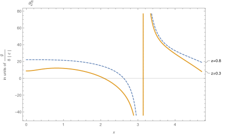
Fig. 3 shows the imaginary angle of the KR, Eq. (20), for two different RHM of different surface impedance versus . at shows a discontinuity. We also note that zeroes for both and coincide and are the solutions to the transcendental equation . At this point there is linearly polarized light for both the reflected and transmitted light.
IV Summary
We study the Faraday and Kerr rotations of light with angular frequency passing through a RHM/LHM film with thickness L while taking into account the multiple reflections from the boundaries. The descriptions of the real portions as the linear angle of rotation and imaginary portions as the ellipticity of the rotation allow us to separate the two distinct phenomena and visualize their maximums and effects within different kinds of mediums. We found that the rotation and ellipticity of the transmitted or reflected light has shown that the real parts of the complex angle of the Faraday and Kerr effects are odd functions with respect to the refractive index n. As well, the imaginary portion of the angle is an even function of n. These odd and even functions are not just the properties of a thin film, but apply just as well to the case of any system of arbitrary length.
For a spatially symmetric film with no material loses the real portion of Faraday and Kerr rotations are equal for RHM and LHM. In the limit of an ultra thin LHM film under specific circumstances a large resonant enhancement of the reflected KR angle could be experimentally obtained. From this it has been shown that with multiple reflections within the medium that the maximums of the real portions of the Faraday and Kerr effects do not coincide with simultaneously zero imaginary portions (figure 2). This means that the maximums of both Faraday and Kerr rotations occur only when the light has some ellipticity, or with non-zero imaginary portions. Taking into account these multiple reflections also shows the resonant enhancement that is now possible with LHM such as the super lattice system, and opens the field of optics to new compositions of materials that can greatly enhance these rotations by an order or more.
References
- (1) Yang, Y. Xu, J. Chen, H. & Zhu, S. Quantum, ”Interference Enhancement with Left-Handed Materials,” Phys. Rev. Lett., American Physical Society, /textbf2008, 100, 043601.
- (2) Willie J. Padilla Dimitri N. Basov, D. R. S. ”Negative Refractive Index Metamaterials,” Materials Today, 2006, 9.
- (3) V. Veselago, The ”Electrodynamics of Substances with Simultaneously Negative Values of and ,” Soviet Physics Uspekhi, 1968, 10.
- (4) E. J. Torres-Herrera, F. M. Izrailev, & N. M. Makarov, ”Non-conventional Anderson localization in a matched quarter stack with metamaterials,” New Journal of Physics, 2013, 15, 055014.
- (5) D. Thouless, ”Electrons in disordered systems and the theory of localization,” Physics Reports, 1974, 13, 93 - 142.
- (6) D. R. Smith, J. B. Pendry, & M. C. K. Wiltshire, ”Metamaterials and Negative Refractive Index,” Science, American Association for the Advancement of Science, 2004, 305, 788-792.
- (7) D. R. Smith, W. J. Padilla, D. C. Vier, S. C. Nemat-Nasser, & S. Schultz, ”Composite Medium with Simultaneously Negative Permeability and Permittivity,” Phys. Rev. Lett., American Physical Society, 2000, 84, 4184-4187.
- (8) Siming Yang Peng Liu, M. Y. Q. W. J. S. & L. Dong, ”From Flexible and Stretchable Meta-Atom to Metamaterial: A Wearable Microwave Meta-Skin with Tunable Frequency Selective and Cloaking Effects,” Scientific Reports, 2016, 6.
- (9) D. Schurig, J. J. Mock, B. J. Justice, S. A. Cummer, J. B. Pendry, A. F. Starr, & D. R. Smith, ”Metamaterial Electromagnetic Cloak at Microwave Frequencies,” Science, American Association for the Advancement of Science, 2006, 314, 977-980.
- (10) M. Sadatgol, M. Rahman, E. Forati, M. Levy, & D. O. Güney, ”Enhanced Faraday rotation in hybrid magneto-optical metamaterial structure of bismuth-substituted-iron-garnet with embedded-gold-wires,” Journal of Applied Physics, 2016, 119.
- (11) J. B. Pendry, ”Negative Refraction Makes a Perfect Lens,” Phys. Rev. Lett., American Physical Soc.iety, 2000, 85, 3966-3969
- (12) N. Papasimakis, & N. I. Zheludev, ”Metamaterial-Induced Transparency:Sharp Fano Resonances and Slow Light” Opt. Photon. News, OSA, 2009, 20, 22-27.
- (13) Margarita I. Sharipova, Alexander I. Musorin, T. V. D. & A. A. Fedyanin, ”Ultrafast dynamics of Faraday rotation in thin films” Proc. SPIE, 2015, 9502, 95020O-95020O-12.
- (14) Lev Davidovich Landau, E. M. L., Press, P. (Ed.) Electrodynamics of Continuous Media Science, 1984.
- (15) U. Leonhardt, ”Optical Conformal Mapping,” Science, American Association for the Advancement of Science, 2006, 312, 1777-1780.
- (16) M. Inoue, K. Nishimura, & T. Fujii, ”Localization and hopping of magnetoelastic waves in highly magnetostrictive strings with random chain structures,” Journal of Applied Physics, 1997, 81, 5692-5692.
- (17) Z. Gevorkian, & V. Gasparian, ”Plasmon-enhanced Faraday rotation in thin films,” Phys. Rev. A, American Physical Society, 2014, 89, 023830.
- (18) V. Gasparian, M. Ortu no, J. Ruiz, & E. Cuevas, ”Faraday Rotation and Complex-Valued Traversal Time for Classical Light Waves,” Phys. Rev. Lett., American Physical Society, 1995, 75, 2312-2315.
- (19) V. E. A. Caligiuri, ”Dielectric singularity in hyperbolic metamaterials: the inversion point of coexisting anisotropies,” Sci. Rep., 2016, 6.
- (20) O. del Barco, & M. Ortu no, ”Localization length of nearly periodic layered metamaterials,” Phys. Rev. A, American Physical Society, 2012, 86, 023846.
- (21) O. del Barco, V. Gasparian, & Z. Gevorkian, ”Localization-length calculations in alternating metamaterial-birefringent disordered layered stacks,” Phys. Rev. A, American Physical Society, 2015, 91, 063822.
- (22) A. A. Asatryan, L. C. Botten, M. A. Byrne, V. D. Freilikher, S. A. Gredeskul, I. V. Shadrivov, R. C. McPhedran, & Y. S. Kivshar, ”Suppression of Anderson Localization in Disordered Metamaterials,” Phys. Rev. Lett., American Physical Society, 2007, 99, 193902.