Increasing Launch Efficiency with the PEGASUS Launcher
Abstract
In the real world application of railguns, the launch efficiency is one of the most important parameters. This efficiency directly relates to the capacity of the electrical energy storage that is needed for the launch. In this study, the rail/armature contact behavior for two different armature technologies was compared. To this end, experiments using aluminum c-shaped armature and copper brush armature type projectiles were performed under same initial conditions. The c-shaped armature type showed a superior behavior with respect to electrical contact to the rails and in acceleration. A 300 g projectile with a c-shaped armature reached a velocity of 3100 m/s and an overall launch efficiency including the power supply of 41%. This is to be compared to 2500 m/s and 23% for the launching of a projectile using a brush armature.
I Introduction
Large caliber railguns are an attractive solution for long range shipboard artillery. They allow large muzzle energies and ranges far in excess of the capability of current deck guns [1, 2]. For a future electrical warship, electric weapons like the railgun and/or the high-energy laser are the logical choice, with respect to capability, integration and economy. A large caliber railgun is a gigawatt launcher with rail currents of several megaamperes. Such an electrical machine requires power close to an order of magnitude above the power generation capability being installed ind current vessels. Ships with the largest installed electrical power are large, modern cruise ships. They are combining several generators to feed the electrical drives and all the other loads. The largest vessels have a total power rating close to or above one-hundred megawatts [4, 3]. In the military domain, the US-Navy recently commissioned the first Zumwalt class destroyer, with 78 MW of installed electrical power [5]. To adopt the required power level for the railgun to the generator power level an intermediate energy storage system is required. Such a system allows a slow charging with lower power and a rapid discharging during firing of the gun. The size of this system is correlated to the muzzle energy divided by the overall efficiency of the launcher system. Even so modern frigates or destroyers are rather large vessels, volume and mass carrying capability are still limited. To maximize the launcher efficiency it is important to reduce electrical losses. For the launcher itself, the most important part is the armature and its contact to the rail surface. The energy losses at this high-speed sliding contact determine to a large extent the ability of the accelerator to convert the energy provided to the launcher into kinetic energy of the payload. Reduced losses at the armature/rail interface will have a beneficial impact on the rail wear and barrel lifetime. In a series of experiment performed at the French-German Research Institute with the PEGASUS railgun installation two different armature types were directly compared. The results of this study clearly favor the widely used c-shaped aluminum armature type.
II PEGASUS Railgun Installation
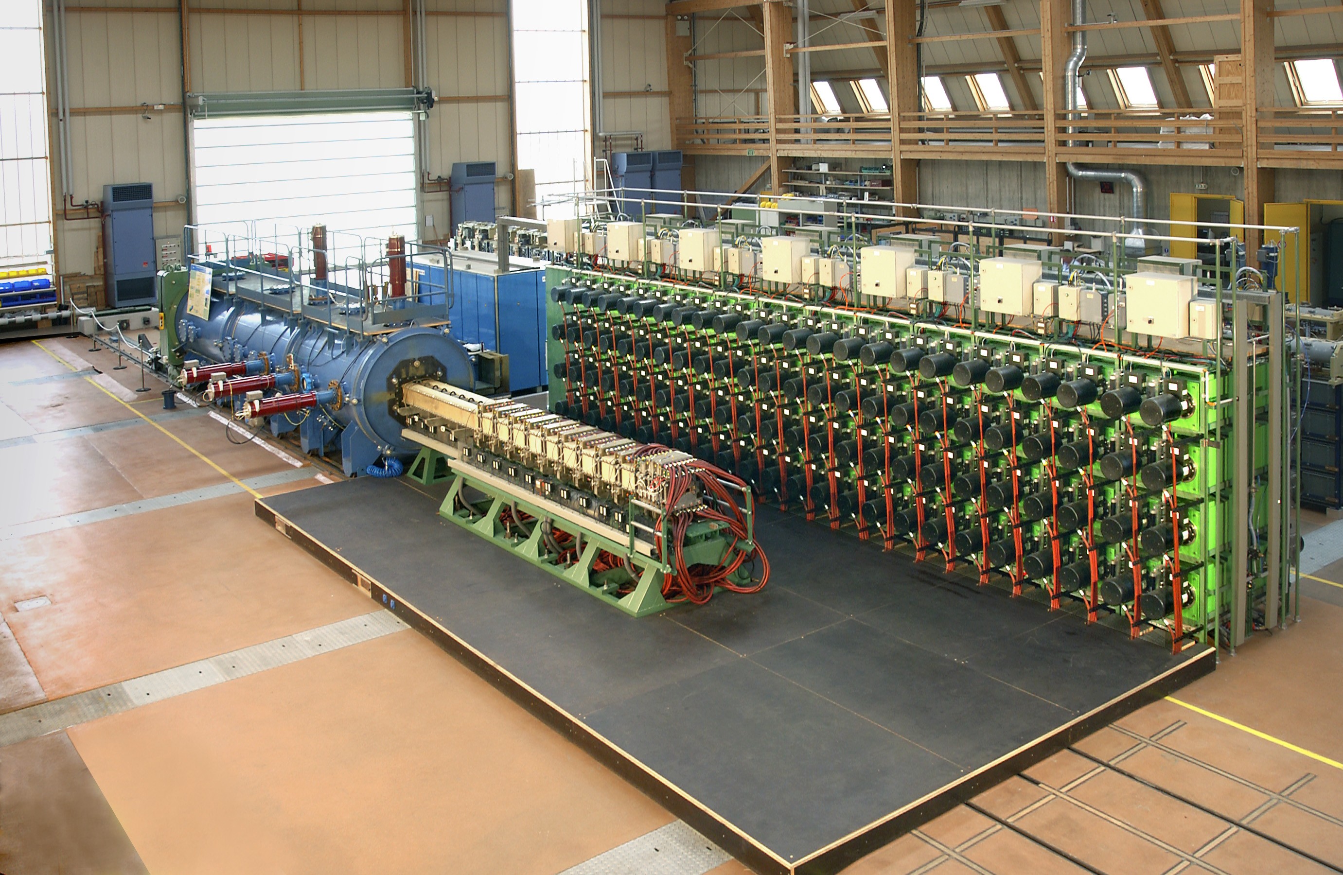
The PEGASUS railgun installation consists out of a railgun barrel, a 10 MJ capacitor based power supply, a 7 m catch tank, a 50 kW capacitor charger and a Faraday cage with the data acquisition and experimental control. Apart from the Faraday cage, the experimental facility is shown in fig. 1. The barrel used in this investigation is a 6 m long, 40 mm square caliber, closed tube with twelve current injection points distributed along the first 3.75 m of acceleration length. This DES (Distributed Energy Supply) scheme allows to follow the armature with the current injection while it propagates down the acceleration length. B-dot sensors installed along the barrel register the passage of the armature. These signals are used to trigger the release of portions of the energy to the different current injection points and to calculate the velocity of the armature. The modularity of the power supply allows to create a current pulse with a nearly flat plateau over much of the acceleration time period, thus allowing for a nearly constant acceleration. As the armature moves down the barrel, the current from current injection points which had been triggered earlier starts to decay and the energy being stored in the magnetic field of this section is used to drive the current through the rest of the barrel. Therefore, in comparison to a breech-fed barrel of the same length, the amount of magnetic energy being stored in the barrel at armature exit is strongly reduced, resulting in a higher launch efficiency [6]. Just before the projectiles leaves the muzzle, an x-ray window in the barrel allows to take a picture of the armature. The catch tank is equipped with different diagnostic devices, most notably 5 flash x-ray tubes, mounts for up to two high speed cameras and several laser barriers. In addition Doppler radar systems installed inside the tank can be used to determine the projectile velocity. These systems are used as an independent means to assess the velocity of the accelerated body. The power supply is composed of 200 capacitor modules with 50 kJ energy capacity, each. The electric circuit attached to the individual capacitors facilitates the transfer of the energy to the gun. Its topology is a typical step-down converter using a thyristor as switch and a crow-bar diode for decoupling of the capacitor. A 28 H coil serves to shape the current pulse from the capacitor. Each module is connected by a 10 m long coaxial cable to the launcher. The 200 capacitor modules are grouped togehter into banks of 16 modules. During a launch these banks are fired in a sequence that is determined by the passage of the armature through the barrel. The rails installed in the gun barrel limit the maximum current to approx. 2 MA.
III Armature Types
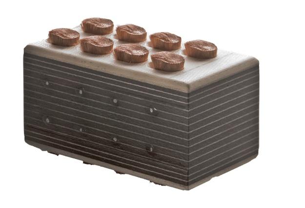
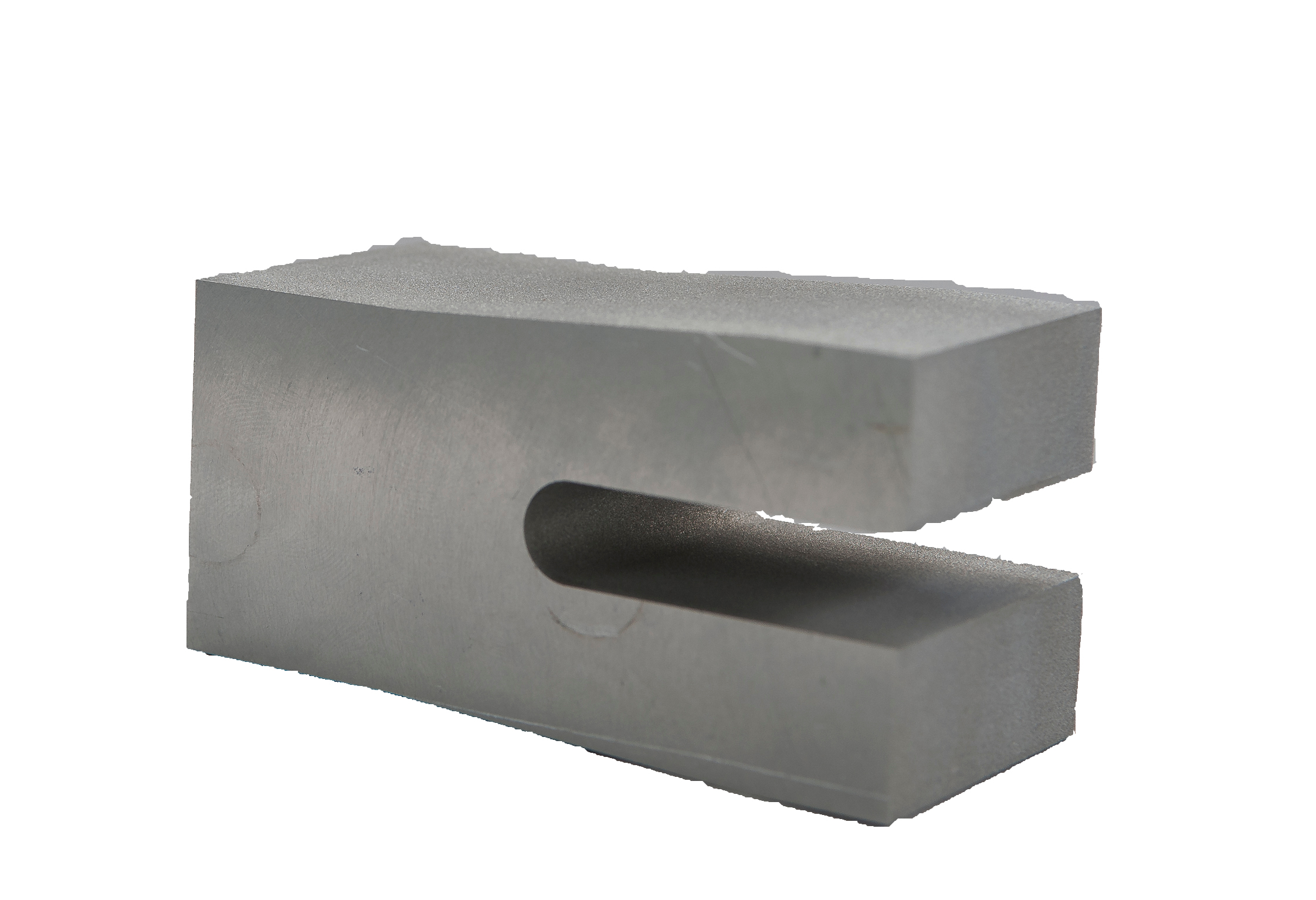
The armature is the key element of the railgun. This sliding short circuit converts electrical into mechanical energy. It has to perform under severe and coupled mechanical, electrothermal and magnetic constraints. Different approaches were taken to find a workable solution that ensures loss-less electrical contact over the full acceleration period, while at the same minimizing the armature mass [7]. Despite of many efforts, it is to be stated, that up-to-today no fully optimal armature technology has yet emerged. One promising approach to solving the armature problem is the metal brush armature, a concept that is extensively investigated at ISL [8, 9, 10]. A representative, simple fiber brush armature is shown in fig. 2. Four pairs of brushes are arranged in an isolating body with an approx. length of 7.5 cm. The body material of the armature shown in this figure is a sandwich made out of layers of glass-fiber and carbon-fiber reinforced plastic (GRP/CRP). The total mass of this armature is 260 g, whereof approx. 50 g is contributed by the copper fiber brushes. To allow for a good initial electrical contact, the brushes are produced and mounted with several millimeters ”overlength”. This reservoir is also used to compensate for material erosion caused by the sliding along the rail surface. A different, simpler approach to solving the high-speed, high-current sliding contact problem is the monolithic c-shaped armature. This type of armature is and was used in many different experiments performed all over the world [11, 12, 13, 14]. An implementation of such an armature as being used at ISL is shown in fig. 3. It is made out of an aluminum alloy and has a mass of 300 g and a length of 80 mm. To ensure sufficient contact pressure at the rail-armature interface the height of the armature at the rear end of the armature arms exceeds the nominal caliber by 2 mm.
IV Experiments
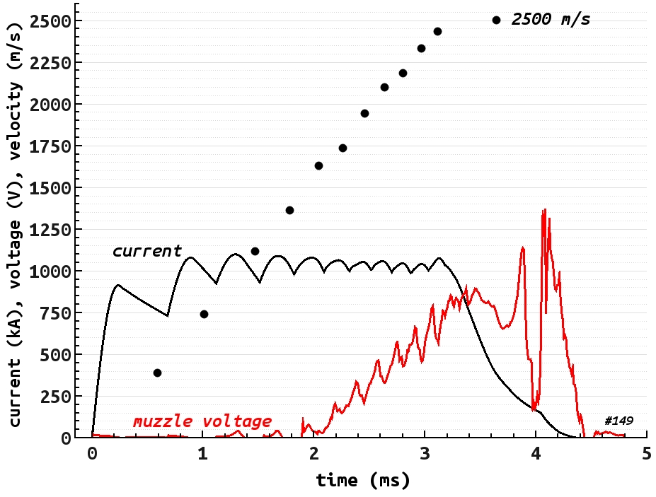
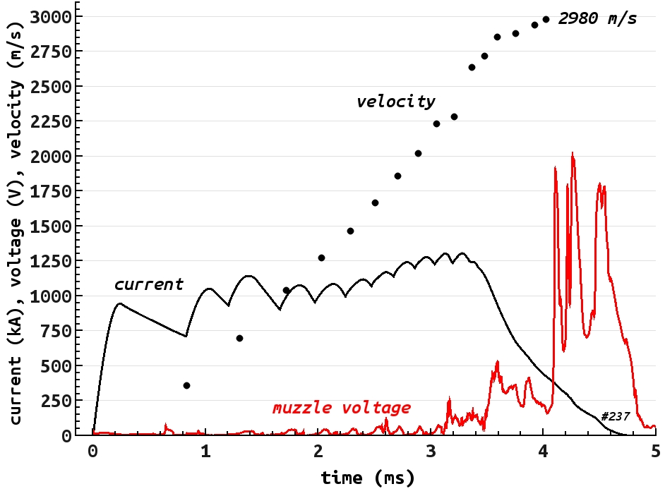
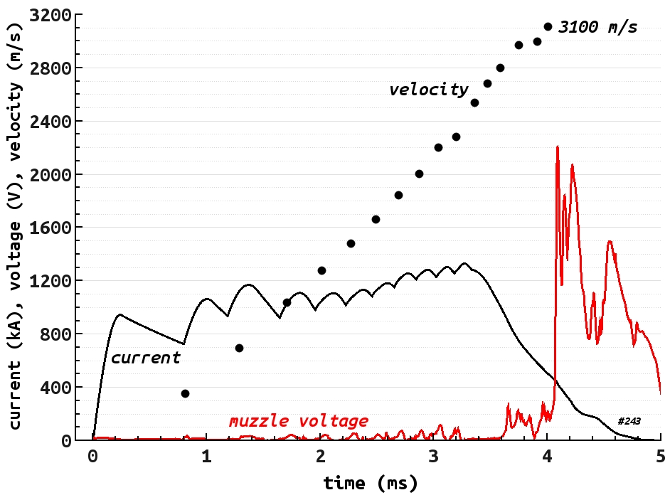
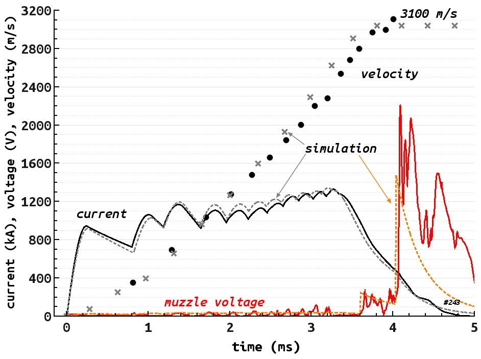
To compare the performance of the two different armature types both were launched at the same energy of 3.6 MJ being stored in the capacitor modules. Results from the launch of the brush armature is shown in fig. 4. The current trace shows the typical behavior of the DES structure of the PEGASUS setup. The different banks of the power supply are triggered by the passage of the armature of the corresponding current injection point of the barrel. Each ”fresh” injection creates a small sub-peak on top of the DC current. Overall, in this launch, the current trace is very close to the preferred rectangular shape, resulting in a constant acceleration of the armature over close to the full barrel length. The current reaches a value of approx. 1–1.1 MA. The contact performance can be interfered from the muzzle voltage measurement, as this value is the voltage drop across the armature/rail interface resistance and the armature resistance. In this shot, the muzzle voltage value is low until approx. 2 ms. Up to this time, the contact is a good metal-to-metal contact and the magnitude of its resistance is well below 0.01 m. After this time, the direct contact between the brush and the rails fail on at least one side of the armature. The short distance in between rail surface and brush tip is bridged by small plasma arcs. The resistance of the plasma is larger than the metal-to-metal contact and the muzzle voltage increases up to approx. 900 V, corresponding to about 1 m. To asses the energy lost at this contact, the current is multiplied with the muzzle voltage and integrated until shot-out of the armature, resulting in a value of 0.83 MJ. This is 23% of the initially stored energy in the capacitors. B-dot sensors, distributed along the barrel are used to determine the time of the passage of the armature. From the known positions and the measured passing times, the velocity of the armature is calculated. As the current is very close to being constant, the acceleration is constant, too. This is reflected in the linear slope of the measured velocity curve. The armature reaches a muzzle velocity of 2.5 km/s and thus an efficiency111Efficiency is here defined as energy stored in the capacitors before the shot divided by the kinetic energy. of 23%. After having discussed the launch using a brush equipped armature, a monolithic c-shaped aluminum armature launch is presented in the following. Figure 5 shows the result: For the first shot using an aluminum armature, the current trace shows nearly exactly the same values as in the previous discussed shot until approx. 2.5 ms, from this time on, the current begins to rise slowly up to 1.3 MA. This increase in current corresponds to the much lower values in muzzle voltage during the later phase of the acceleration. The contact in between the armature and rail surface has a lower resistance as compared to the above described launch of the brush equipped armature and only 0.25 MJ or 7% of the initial energy are lost at the contact resistance. The muzzle velocity of the armature was determined to be 2980 m/s, corresponding to an efficiency of 37%. This is a significant improvement in efficiency to the launch under similar conditions with the brush armature. To confirm this result, the exceptional good contact despite of the usage of worn rails and the excellent overall efficiency, a second shot using an aluminum c-shape armature with similar parameters was performed. In between the first and second shot with this type of armature, the rails of the PEGASUS barrel were replaced and therefore the rail surface conditions for the second shot were better. The results are shown in figure 6. Interpreting the muzzle voltage allows to state, that the rail/armature contact was excellent until 3.6 ms, only to deteriorate slightly after this time until shot-out at 4.1 ms. The energy lost at the contact resistance can be determined to be 120 kJ, less than half of the value of the similar shot described before. With a velocity of 3100 m/s, a launch efficiency of 41% is reached. The parameters and results for the different shots are summarized in table I. Without doubt, the c-shaped aluminum armature in direct comparison to a brush equipped armature, is able to better convert electrical energy into kinetic energy. Despite the large velocity of approx. 3 km/s and the condition of the rails, for both launches the rails were already used from other shots, the monolithic armature performs with excellent contact behavior over the full acceleration length.
| brush | c-shape #1 | c-shape #2 | |
| E | 3.6 MJ | 3.6 MJ | 3.6 MJ |
| mass | 260 g | 300 g | 308 g |
| v | 2500 m/s | 2980 m/s | 3100 m/s |
| E | 0.81 MJ | 1.3 MJ | 1.48 MJ |
| E | 0.83 MJ | 0.25 MJ | 0.12 MJ |
| 23% | 37% | 41% |
V Simulations
To gain further insight a SPICE simulation was performed for one of the experiments with the aluminum c-shaped armature. This allows to further investigate the launch efficiency and importance of the different energy loss processes. In addition, with the electrical circuit being implemented into the simulator, detailed information about values that are not easily accessible in the experiment become available. An important example are the identification of the different contributions to power loss.
V-A Simulating the PEGASUS Railgun
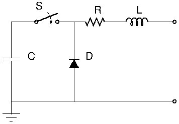
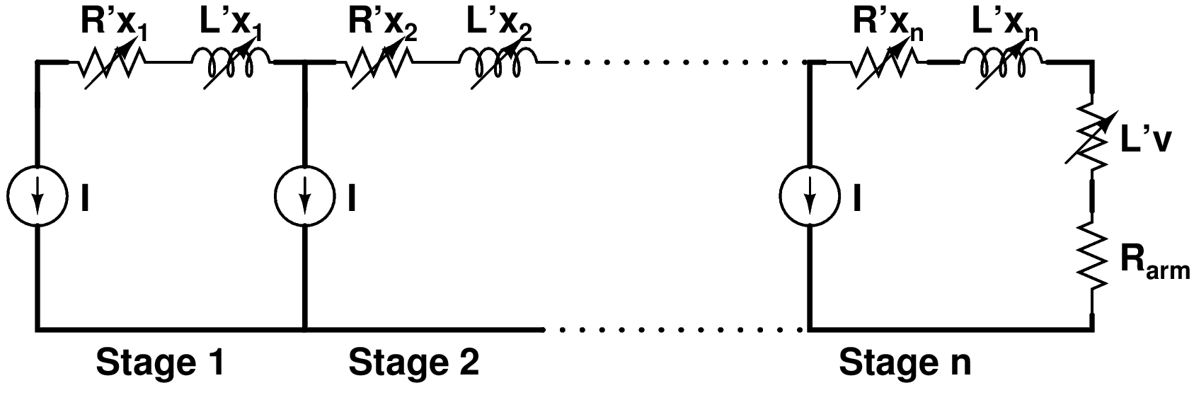
The NGSPICE [15] simulator is used to simulate the electrical circuit of the railgun. Figure 7 shows the circuit of the the power supply unit (PSU) as implemented into NGSPICE. It consists out of a capacitor, a switch, a crow-bar diode, a resistance and an inductor. To simplify the circuit, the resistance and inductance of the cable connecting the module to the launcher are integrated into the resistance and the inductance of the module. In this setup the small difference in resistance and inductance that occurs, once the crowbar diode becomes conducting and the switch and capacitor are disconnected from the current flow is neglected. This simplified circuit was tested against experimental short circuit data and showed good overall accuracy [6]. In figure 8 the schematic representation of the PEGASUS DES railgun is depicted. Several capacitor modules (shown in the figure as current sources) are connected at different positions to the rails. The sub-circuit, including a power supply and the rail section until the next current injection point is called a stage. As the armature propagates through the rail section of a stage, the inductance and resistance grows linearly with the distance traveled up to its maximum value (determined by the length of the stage). This is reflected in the circuit by the variable resistance and inductance , where stands for the path length the armature has traveled within the stage. After the armature has propagated through one stage, it enters the next stage. Once all current injection points are passed, all the capacitor modules are connected in parallel via the rails. In addition to the rail resistance, the resistances L’v and R are taken into account, too. It is important to note, that current injected at different positions, ”sees” different values of resistance and inductance. Thus the DES system is a fairly complex engine, combining currents charging inductances, while at the same time inductances from stages with dropping current inflow convert magnetic energy into electrical current flow.
V-B Simulating the C-shaped Armature Launch
Due to the interplay of the different stages, the DES setup is more difficult to simulate than the simple, breech fed railgun. In figure 9 the results from the simulation for the second launch is compared to the experimental data. The simulated current does agree quite well with the measured, experimental current data. The muzzle voltage is determined by the resistance of the armature including its contacts to the two rails. The value of this resistance is not exactly known during sliding contact. To be able to compare experiment and simulation, the armature and plasma resistance (small bumb after 3.6 ms) in the simulation was adjusted such that the energy loss at the armature until shot-out is the same for both cases. The acceleration and therefore the velocity is well matched between simulation and experiment. Using this simulation, with the main launch parameters being well described by the simulation, it is possible to investigate the acceleration process in more detail.
V-C Power of the Railgun System
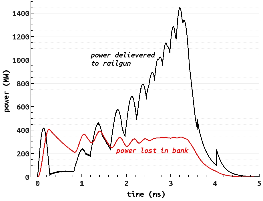
In the simulation, the power being delivered from the individual banks of the PSU to the railgun can be accessed. For every instance in time, the total power supplied to the gun is the sum of these contributions. In figure 10 this power being delivered to the railgun is shown. The trace consists out of 2 parts. First we have a bump of up to 400 MW from start to 0.3 ms, this is followed by a rising slope until 3.1 ms. When the experiments starts, the cables to the railgun and the rails from the breech to the starting position of the armature are current free. Once triggered, the current flows and the volume up to the armature is filled with magnetic energy. During this time, the PSU has to overcome the counter voltage of the inductance from the cables and the rail section until the armature starting position. Only if the current has reached a large enough value to overcome the initial friction of the armature does the acceleration process start. The current increases further until the energy of the corresponding bank is spent. This is marked by the downturn of the power trace up to a time of 0.3 ms. It takes until 0.8 ms for the armature to reach the next injection point. From 0.3 ms to 0.8 ms the acceleration is driven by the decaying magnetic field of the first stage. After the second bank has triggered, the power delivered by the PSU to the gun describes a steeply raising function, reaching a peak value of 1.45 GW at the end of the acceleration process. The main reason for this increasing power is the speed voltage which grows linearly with the velocity and is multiplied by the nearly constant current. Or to phrase the same fact slightly different, the banks are current sources which must overcome a larger voltage with increasing armature velocity, thus the energy in the banks is discharged in smaller time periods. Integrating the power delivered to the terminals of the railgun barrel over time results in the energy being supplied to the railgun. For this shot, this energy amounts to 65% of the initial energy stored in the capacitor banks. The remaining part is spent in the PSU including the cables. To investigate this, the power lost in the bank including the cables is shown in figure 10, too. Apart from the initial acceleration phase, this value is relatively constant at 350 MW. Integrated over time results in the remaining 35% of the initial energy. One consequence of this behavior is, that the relative power losses caused by the components of the PSU becomes smaller, the faster the projectile is. This will result in an increased efficiency for shots with a higher end-velocity.
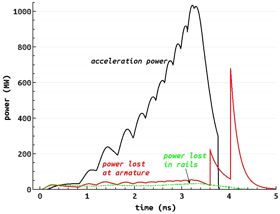
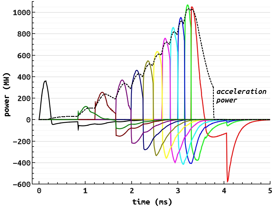
The power that is used to accelerate the armature is calculated as time derivative of the kinetic energy of the armature. In the simulation, the average acceleration power over the full launch period is 375 MW. In figure 11 it is shown, that this power is strongly raising with acceleration time. At shot-out, the power has surpassed 1 GW. This increase is easy to understand. Mechanical power is defined as force times velocity. In this railgun launch the current is approximately constant, so is the acceleration force. This means, that to first order, the acceleration power grows linearly with the velocity. Two smaller contributions to the power loss in the DES launcher are from the voltage drop at the armature (armature resistance and armature/rail surface contact resistance) and the losses from the rail resistance. The DES system reduces the rail losses drastically as compared to a breech feed system (as shown in [6]). Nevertheless a heating level of approx. 30 MW is not negligible with respect for rail temperature increase, especially when considering a scenario which involves the firing of several successive rounds. Comparing figures 10 and 11 shows two things: 1) the power lost in the components of the banks is by a factor of approx. 10 larger than the power lost in the rails. 2) the acceleration power, the armature loss power and rail loss power do not add up to the power delivered to the railgun. The ”missing” power is used to fill the railgun stages with magnetic energy and is stored in the inductance of the rails. In figure 12 the power used to build up the magnetic field in the rail section which correspond to the different stages is shown. It can be seen, that once the armature has propagated into the subsequent stage, the magnetic field in the previous stage decays and the power becomes negative. This means the magnetic field from previous stages is used to drive the current and therefore accelerate the armature through the following stages. The result of this behavior is, that a large part of the gun barrel is already ”emptied” from the magnetic field when the armature leaves the barrel at 4 ms. From the figure one can determine, that only stages 10 to 12 still contribute at shot-out. In an ideal railgun, half of the power delivered to the gun goes into building up the magnetic field and half is converted into kinetic energy of the short-circuit [16]. This is verified by overlaying the acceleration power onto the power needed to build up the magnetic field in figure 12. Owing to an assumed 5% loss due to friction, the acceleration power is slightly smaller than the magnetic field power. But apart from this small deviation, the equipartition between kinetic energy and magnetic energy is clearly seen. Inspecting figure 10 and figure 12, there seems to be a contradiction: when adding up the acceleration power and the power required to build up the magnetic field in figure 12, this value is larger than the power being delivered to the railgun (figure 10). For example at the peak at 3.3 ms about 1.45 GW is being delivered to the gun, but the magnetic field built-up and the acceleration power add to more than 2 GW. This conflict of seemingly missing power is solved, when taking into account the power from the decaying magnetic field, which is the negative part of the curves seen in figure 12. Another detail that can be deduced from this figure, is that for the stages 1 to 5, the energy being available in the banks connected to these stages is not sufficient to fully make use of the length of the stages, resulting in a strong decay of the power level, even so the armature has not yet left the stage.
Finally one more number should be calculated: The specific efficiency of the railgun. Usually electric generators and engines are assigned an efficiency which does not take into account losses from previous stages of power conversion. This number becomes important if the quality and further possibility of optimization has to be judged. For the PEGASUS barrel we can calculate an efficiency specific to this linear motor as:
| (1) |
For our simulation this computes to 67%. Comparing the different subsystems of the railgun, it can be deduced, that the launcher has a better efficiency than the PSU including cables, which has an efficiency of 65%. A further improvement of the overall efficiency could therefore be achieved by reducing the losses associated with the cables from the PSU to the railgun.
VI Summary
In an experimental investigation the behavior of a copper brush equipped armature was compared to an aluminum c-shaped armature type. For this, 3 launches at 3.6 MJ initial energy were performed and current, muzzle voltage and velocity were measured. The main difference in between the behavior of the two armature types was the amount of energy that was lost at the rail/armature interface. For the brush armature this loss amounted to 23% of the initial energy, while the c-shaped aluminum armatures had better contact over the full acceleration period and lost only 7% in the first launch and 3.3% in the second. This change in launch behavior translated in an increase of the shot-out velocity of the projectile from 2500 m/s for the brush armature to 3100 m/s for the c-shaped armature. These velocities were reached with an overall launch efficiency, including the power supply of 23% (brush armature) and 37% and 41% for the two launches with aluminum c-shaped armatures. The experiments performed showed that under the given experimental conditions, the aluminum c-shaped armatures performed much better in converting electrical energy into kinetic energy than a brush armature of about the same mass. To gain further insight into the launch performance of the c-shape armature launch, a SPICE simulation for the c-shape armature launch was carried out. The current, muzzle voltage and velocity of the experiment could be reproduced by the results of the simulation. Using this simulation, insight into the power levels involved in the launch were gained. The PSU delivers a power of up to 1.45 GW, of this a nearly constant power of approx. 350 MW is lost in resistances of the PSU including the cables. The acceleration power is on average 375 MW and peaks a little above 1 GW. The same power is used to build up the magnetic field inside of the DES stages. During the launch the stages which the armature has already left support the acceleration by reconverting the magnetic energy to drive the current through the short-circuit. The power losses from rail and armature resistance are only minor compared to the power used for acceleration. One obvious result of this investigation is, that a further increase in launch efficiency can be accomplished by reducing the PSU and cable losses.
Acknowledgment
This research was supported by the French and German Ministries of Defense.
References
- [1] I. R. McNab, Parameters for an Electromagnetic Naval Railgun, IEEE Transactions on Magnetics, Vol. 37, No. 1, January 2001.
- [2] S. Hundertmark, D. Lancelle, A Scenario for a Future European Shipboard Railgun, IEEE Transactions on Plasma Science, Vol. 43, No. 5, May 2015.
- [3] The Queen Mary 2 cruise ship at https://de.wikipedia.org/wiki/Queen_Mary_2 (accessed 04/11/2016).
- [4] The Oasis of the Seas cruise ship at https://en.wikipedia.org/wiki/MS_Oasis_of_the_Seas (accessed 04/11/2016).
- [5] The Zumwalt class destroyer at https://en.wikipedia.org/wiki/USS_Zumwalt (accessed 12/05/2016)
- [6] S. Hundertmark, Simulating the Difference between a DES and a Simple Railgun using SPICE, accepted for publication in Journal of Electrical Engineering (http://www.jee.ro), Vol. 16, Ed. 2, 2016.
- [7] R. A. Marshall, W. Ying, Railguns: their Science and Technology, China Machine Press, ISBN 7-111-14013-3, 2004.
- [8] J. Wey, P. Lehmann, R. Charon, D. Eckenfels, C. Gauthier, First measurements of current distribution in moving fiber-armatures in railguns, IEEE Transactions on Magnetics, Vol. 35, No. 1, Jan 1999.
- [9] S. Hundertmark, M. Schneider, G. Vincent, Payload Acceleration using a 10-MJ DES Railgun, IEEE Transactions on Plasma Science, Vol. 41, No. 5, May 2013.
- [10] S. Hundertmark, D. Simicic, G. Vincent, Acceleration of Aluminum Booster Projectiles with PEGASUS, IEEE Transactions on Plasma Science, Vol. 43, No. 5, May 2015.
- [11] R. J. Hayes and T. E. Hayden, Experimental results from solid armature tests at the Center for Electromechanics at the University of Texas at Austin [railguns], IEEE Transactions on Magnetics, Vol. 29, No. 1, Jan. 1993.
- [12] T. Watt and F. Stefani, Experimental and computational investigation of root-radius melting in C-shaped solid armatures, IEEE Transactions on Magnetics, Vol. 41, No. 1, Jan. 2005
- [13] F. Wang, M. Li, L. Wang, R. Pan, D. Zhang and C. Ren, The experimental research on the sliding performance of solid armature under different sequential pulse current, 2011 International Conference on Electrical Machines and Systems, Beijing, 2011.
- [14] T. E. James, Why solid armatures fail and how they can be improved, IEEE Transactions on Magnetics, Vol. 39, No. 1, Jan. 2003.
- [15] NGSPICE is a mixed-level/mixed-signal circuit simulator, Homepage: http://ngspice.sourceforge.net/ (accessed 03/24/2016).
- [16] R. A. Marshall, W. Ying, C. Shukang Physics of Electric Launch, Science Press, Beijing, China, ISBN 7-03-012821-4, 2004.