Damped spin-wave excitations in the itinerant antiferromagnet -Fe0.7Mn0.3
Abstract
The collective spin-wave excitations in the antiferromagnetic state of -Fe0.7Mn0.3 were investigated using the inelastic neutron scattering technique. The spin excitations remain isotropic up to the high excitation energy, meV. The excitations gradually become broad and damped above 40 meV. The damping parameter reaches 110(16) meV at meV, which is much larger than that for other metallic compounds, e.g., CaFe2As2 (24 meV), La2-2xSr1+2xMn2O7 ( meV), and Mn90Cu10 (88 meV). In addition, the spin-wave dispersion shows a deviation from the relation above 40 meV. The group velocity above this energy increases to 470(40) meVÅ, which is higher than that at the low energies, meVÅ. These results could suggest that the spin-wave excitations merge with the continuum of the individual particle-hole excitations at 40 meV.
pacs:
75.30.Ds, 75.50.Ee, 75.50.BbI Introduction
There has been a renewed interest in magnetic excitations in itinerant antiferromagnets after the discovery of superconductivity in copper oxides Lee et al. (2006) and iron pnictides/chalcogenides Kamihara et al. (2008). These superconductivities emerge near the antiferromagnetic ordered phases, and it is believed that spin fluctuations play a role in binding Cooper pairs. Mechanism of the spin-wave excitations remains under debate in the iron pnictides/chalcogenides. The spin-wave excitations are highly in-plane anisotropic with a large damping at the high energy region ( meV) of Fe2As2 ( Ba, Sr or Ca) Harriger et al. (2011); Ewings et al. (2011); Diallo et al. (2009). Various mechanisms were proposed to explain the in-plane anisotropy, which are based on local-moment models with electron nematic ordering Fang et al. (2008) and orbital ordering Chen et al. (2010), itinerant models Knolle et al. (2010); Kaneshita and Tohyama (2010); Kovacic et al. (2015), and the combination of itinerant and localized characters Park et al. (2011); Yin et al. (2011). To have a profound understanding of the spin excitations in the superconductors and related compounds, we need some background knowledge about the spin excitations in prototypical itinerant antiferromagnets.
Metallic chromium, -FeMn, -Mn, and -Fe are prototypes of itinerant antiferromagnets. Chromium and -FeMn are gap-type antiferromagnets Asano and Yamashita (1971), as well as iron pnictides Mazin et al. (2008). -Mn and -Fe are band-type antiferromagnets Asano and Yamashita (1971). The gap-type antiferromagnetic states are induced by the nesting of the Fermi surfaces, while the band-type antiferromagnetic states are induced by the interband mixing due to the large spin-dependent perturbation Asano and Yamashita (1971). In itinerant antiferromagnets, the maximum energy of the collective spin-wave excitations is relatively high compared that of Heisenberg magnets Kohgi and Ishikawa (1980), and thus the overall picture of the excitations has not yet been clarified Ishikawa (1978); Endoh and Böni (2006). For example, the dynamic structure of chromium consists of incommensurate excitations below 20 meV Fincher et al. (1981) and commensurate excitations localized at the antiferromagnetic wave vector, which extends up to more than 550 meV Heap et al. (1991); Lowden et al. (1995); Hayden et al. (2000). A recent theoretical study Sugimoto et al. (2013) based on a multi-band Hubbard model predicted that the commensurate excitations merge with the continuum of the individual particle-hole excitations above 600 meV. However, spin excitations above 600 meV have yet to be elucidated experimentally because inelastic neutron scattering experiments are difficult in this high-energy transfer region.
In particular, an experimental understanding of spin-wave damping due to the continuum of the particle-hole excitations is still lacking in itinerant antiferromagnets compared to that in itinerant ferromagnets Ishikawa (1978); Endoh and Böni (2006). To reveal how spin-wave excitations are damped at high energies in the gap-type itinerant antiferromagnets, we focused on -FeMn, whose spin-wave velocity is much smaller than of metallic chromium. The FexMn1-x alloy () is crystallized in a face-centered cubic structure, the so-called -phase. The Fe and Mn ions are located randomly at the origin and face center positions. -FeMn shows the antiferromagnetic transition in the temperature range K, depending on the composition Kouvel and Kasper (1963); Umebayashi and Ishikawa (1966); Endoh and Ishikawa (1971); Ishikawa et al. (1974). Asano et al. Asano and Yamashita (1971) revealed that the magnetic order is a spin-density-wave (SDW) order using a band calculation. The Fermi surfaces show good nesting with for . The magnetic structure is under debate experimentally and theoretically Kawarazaki et al. (1990); Kennedy and Hicks (1987); Bisanti et al. (1987); Hirai and Jo (1985); Sakuma (2000); Ekholm and Abrikosov (2011). The candidates are collinear single-SDW or non-collinear triple-SDW structures. Both Fe and Mn ions have magnetic moments. The average moment size is in the range Kouvel and Kasper (1963); Nathans and Pickart (1964); Ishikawa and Endoh (1967); Endoh and Ishikawa (1971), where is the Bohr magneton. Studies of the spin-wave dispersion up to 56 meV Tajima et al. (1976); Endoh et al. (1973) have reported that the spin-wave excitations follow the relation,
| (1) |
where is the excitation energy and is the distance from the antiferromagnetic zone center . The spin-wave velocity is about meVÅ and the energy gap about meV at room temperature (RT) for Tajima et al. (1976). Endoh et al. Endoh et al. (1973) observed strong damping of the spin-wave excitations at meV, possibly due to particle-hole excitations. However, the dispersion and damping ratios are not known above this energy. Therefore, in this study, we performed inelastic neutron scattering measurements on -FeMn to investigate the spin-wave excitations at high energies. This investigation will enhance our understanding of spin excitations in itinerant antiferromagnets. In addition, the existence of the double- magnetic states has been recently proposed in the tetragonal magnetic phase of hole-doped iron pnictides Wang et al. (2015); Scherer et al. (2016). Spin-wave excitations and damping effects are keys to tell two possible double- states Scherer et al. (2016). This study could offer some insights into the double- states of iron pnictides.
II Experimental details
The composition was selected, because the average moment size is the largest in the -phase. A Fe0.7Mn0.3 crystal was synthesized by a Bridgman type induction furnace. The details have been described elsewhere Endoh and Ishikawa (1971). The mass of the grown single crystal was about 40 g. The antiferromagnetic ordering temperature for this composition is known to be K with the average magnetic moment being 1.97 Ishikawa and Endoh (1967). The crystal orientation was determined using the x-ray Laue method (YXLON MG452, 450 kV/5 mA). Inelastic neutron scattering experiments were performed on the High Resolution Chopper Spectrometer (HRC) Itoh et al. (2011, 2013, 2015) installed at the Materials and Life Science Facility, in the Japan Proton Accelerator Research Complex. DAVE/MSlice Azuah et al. (2009) was used for analyzing the data. The initial neutron energies were set between 33 and 372 meV. The energy resolution was determined using the incoherent elastic scattering of a solid vanadium, while the angular resolution was geometrically estimated. The sample was mounted with a horizontal scattering plane, sealed in an aluminum can under a 4He gas atmosphere, and then set in a closed cycle 4He cryostat. Measurements were performed at K. The lattice parameter was Å at that temperature.
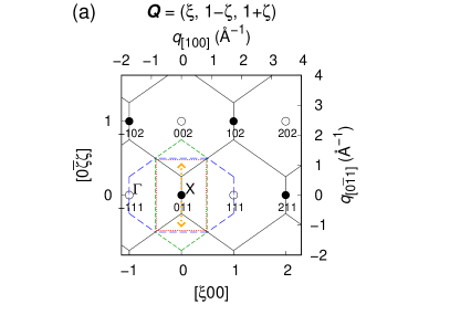
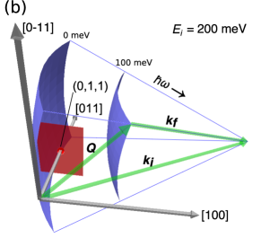
The Brillouin zone for -FeMn is shown in Fig. 1(a). Antiferromagnetic zone centers are located at the symmetry point . All the measurements were performed around the magnetic zone center . Figure 1(b) shows a typical measurement condition for the neutron scattering measurements. By measuring the fixed crystal angle, the scattering intensity is obtained on the blue curved surfaces for each . Thus, of the measured intensity varies on the red rectangle zone. The scattering intensities for constant- and - can be obtained by several measurements with different crystal angles. In this study, measurements with rotating crystal angles were adopted to obtain the map, which is shown in Fig. 2. For the other measurements, fixed angle measurements were adopted due to the limited beam time.
III Results
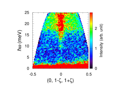
The map around is shown in Fig. 2. The measured position corresponds to the orange dotted arrow in Fig. 1(a). Spin-wave excitations with an energy gap of about 10 meV are found at . The uniform scattering above 15 meV is a background from aluminum polycrystals contained in the instruments and the sample can.
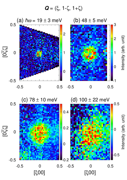
Figures 3(a-d) show the maps through with , 48, 78, and 100 meV, respectively. The measured range corresponds to the red dotted rectangle in Fig. 1(a). The edge of the panel is the zone boundary for the triple-SDW structure. At (a) 19 meV, the magnetic excitations are localized at within reciprocal lattice unit (r.l.u.) in all three directions [100], [110], and [111]. At (b) 48 and (c) 78 meV, the excitations open up in space. Both excitations spread as circles, which indicate that the dispersion is isotropic. At (d) 100 meV, the excitations further spread compared to that at (c) 78 meV, but the spin-wave excitations do not reach the zone boundary even at this high energy. The excitations gradually become broad with increasing .
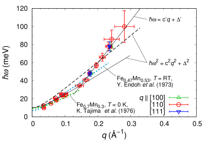
To obtain the dispersion relation quantitatively, the spin-wave excitations around were fitted to double Gaussians in [110]. In addition, to confirm the isotropy, the excitations were fitted in [100] and [111] in the same manner for and 78 meV. For the backgrounds, linear functions were used for [110], while cubic polynomial functions were used for [100] and [111] due to the volatile backgrounds in these directions. Figure 4 shows the dispersion relation obtained by the fitting procedure. At 48 and 78 meV, there is no difference in the peak positions between all the directions within the experimental error, which indicates that the dispersion is isotropic even at 78 meV. This is consistent with the report Endoh et al. (1973) that the dispersion is isotropic in [100] and [110] up to 35 meV. Secondly, we tried to fit the dispersion relation with a function. The energy gap was fixed to meV in the following fitting procedure, which was obtained with the dependence of the local spin susceptibility as described later. The black dashed curve in Fig. 4 shows the fit with Eq. 1, which indicates that the function is unsuited. The dispersion could be fitted with Eq. 1 only below 40 meV. The black solid curve in Fig. 4 shows the fit below 40 meV. The spin-wave velocity is meVÅ. Below this energy, the dispersion is reasonably consistent with those in the previous reports for Fe0.7Mn0.3 [ meVÅ] at K Tajima et al. (1976) and Fe0.47Mn0.53 ( meVÅ) Endoh et al. (1973) at RT, shown by the dotted curves in Fig. 4. Above 40 meV, the gradient of the dispersion relation is considerably larger than that expected from Eq. 1. The linear fit with the function, , above 40 meV yields the group velocity meVÅ.
 The solid lines represent the fits.
To obtain the lifetime of the excitations as a damping parameter , the scattering intensity along [01] through was fitted to convoluted with the instrumental resolution adding a linear background in . In this analysis, the following equation based on the damped harmonic oscillator in was assumed:
| (2) | |||||
| (3) |
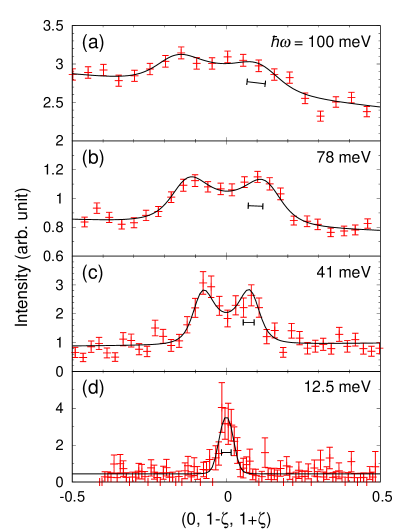
where is the Boltzmann constant. is the dispersion relation. An appropriate should be given to Eq. 3 before the fitting. We note that the data are not fitted well if is assumed to be Eq. 1. Here, is assumed to be the dispersion relation extracted above. The dependence of the magnetic form factor was ignored because of the small variation. This analysis is equivalent to the earlier report Tajima et al. (1976). Figure 5 shows the fitting results for 100, 78, 41, and 12.5 meV. At all energies, the scattering intensities were fitted well with the above model function. The observed peak widths are wider than the resolutions, and therefore, the peak broadening is an essential nature of the observed excitations.
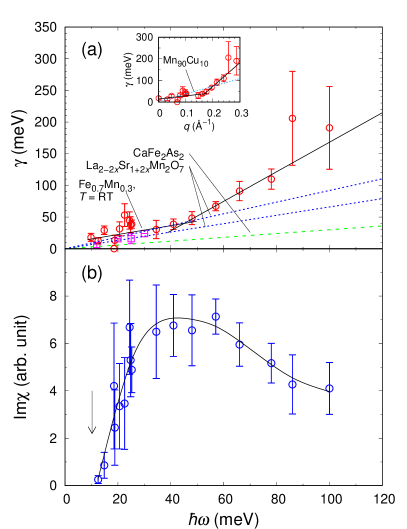
The obtained parameter is shown in Fig. 6(a). below 30 meV is in agreement with the previous report Tajima et al. (1976) at RT. shows steady increase above approximately 40 meV, and reaches 110(16) meV at meV. below 40 meV is similar to that of the metallic compound, the bilayer colossal magnetoresistive manganites La2-2xSr1+2xMn2O7 () Perring et al. (2001), but larger than that of another metallic compound, the parent compound of iron superconductor CaFe2As2 (0.3) Zhao et al. (2009). above 40 meV is much larger than those of both compounds. The inset of Fig. 6(a) shows dependence of . increases steadily above Å-1. In Mn90Cu10, which is a dilute alloy of the band-type itinerant antiferromagnet -Mn, was found to be linear in Fernandez-Baca et al. (1992) as shown by the sky-blue dotted line. is of the form , where meV and meVÅ below 0.8 Å-1 Fernandez-Baca et al. (1992, 1993). An increase in the rate of change of was not observed in these three compounds. Note that, in these reports, is determined in the same manner as this study under the assumption of a damped simple harmonic oscillator.
Next, the local spin susceptibility Im, which is approximately proportional to the integrated intensity, was derived using the following equations,
| (5) | |||||
where the integration was performed within a magnetic Brillouin zone. The energy dependence on , which came from the measurements with the fixed crystal angle, was ignored because the gradient of the dispersion relation is large. is the background function, which was determined using the intensity away from . For example, intensity around was used for the background at . Figure 6(b) shows Im. The energy gap was estimated to be (14 K) meV by linear extrapolation of Im below 15 meV. The result is consistent with the value previously reported Tajima et al. (1976), (0 K) meV, which was derived from the temperature dependence of . Im reaches the maximum value around 40 meV and clearly decreases above 60 meV.
IV Discussion
The high group velocity and isotropic dispersion of the spin-wave excitations in Fe0.7Mn0.3 are common to the commensurate spin excitations in chromium and its dilute alloys. The spin-wave velocity in dilute alloys of chromium is more than 1000 meVÅ Als-Nielsen et al. (1971); Sinha et al. (1977) if the commensurate excitations are assumed to be spin-wave excitations. In pure chromium, width of the commensurate mode remains constant from 350 to 550 meV Lowden et al. (1995). The spin-wave velocities are at least an order of magnitude larger than that in -FeMn. This suggests that the Fermi velocities of the nested bands are smaller in -FeMn than those in chromium and its dilute alloys Fedders and Martin (1966). This is consistent with the large thermal effective electron mass in -FeMn observed in the electronic specific heat measurements Gupta et al. (1964); Hashimoto and Ishikawa (1967). In itinerant magnets, dispersions are isotropic in many cases. However, an anisotropic dispersion may be observed near the zone boundaries if the spin wave remains well defined, as calculated for Fe, Co, and Ni Halilov et al. (1998). The isotropic result will not determine the spin structure of -FeMn. With a localized spin model Jensen and Bak (1981), an isotropic dispersion is expected at low for the triple-SDW spin structure. However, Tajima et al. reported Tajima et al. (1976) that the scattering profiles are inconsistent with those of the calculation. Theoretical works based on itinerant electron models will be needed. Note that Sato and Maki studied Sato and Maki (1976) the spin fluctuations with a two-band model near the transition temperature, but the analysis was performed under the condition of spherical Fermi surfaces.
The energy gap could originate by the spin-orbit interaction. The spin-orbit scenario expects that SDW has an orbital character. The existence of the spin-orbit coupling was suggested by Ishikawa et al. Ishikawa et al. (1973) They found the anisotropy of the critical scattering in -FeMn. The origin of the large energy gap might have a relationship with Weyl fermions. It is suggested that the Berry phase induces the orbital ferromagnetism and anomalous Hall effect for the triple-SDW spin structure in -FeMn when the crystal structure is distorted Shindou and Nagaosa (2001); Fang et al. (2003), and the effect of the Berry phase is observable with inelastic neutron scattering Itoh et al. (2016). Although either ferromagnetism or crystal distortion have not yet been observed in -FeMn, the large energy gap and the anisotropic critical scattering imply the existence of the Berry phase. To elucidate of the origin of the large energy gap in -FeMn, further investigations are required.
It is really strange that the group velocity of the spin wave suddenly increases at 40 meV and that the spin-wave dispersion deviates from Eq. 1. This indicates the existence of other excitations that interact with the spin wave, because the group velocity decreases with energy if the spin wave does not interact. This result strongly suggests that the spin wave merges with the continuum of the individual particle-hole excitations at 40 meV. When a spin wave enters the continuum, an increase in the group velocity is expected for a ferromagnetic electron gas Ishikawa (1978). On the other hand, a magnon-electron interaction will not cause a sudden change. The relatively large is in agreement with the origin of the damping. Im gradually decreases above 60 meV and steadily increases above 40 meV, which indicates that the spin wave gradually damps with increasing in the continuum. A similar dependence of Im and was reported at the boundary of the particle-hole excitations in the weak itinerant ferromagnets MnSi Ishikawa et al. (1977). Note that because the neutron scattering cross section of the particle-hole excitations is quite small, it is difficult to measure the excitations directly. Of course, other scenarios for explaining the excitations cannot be ruled out. The site randomness may be another possibility. The inhomogeneously distributed moments caused by the randomly located Fe and Mn ions Kimball et al. (1963); Ishikawa and Endoh (1967) could disturb propagation of the spin wave. At least, it is unique that the spin-wave excitations show the linear dependent dispersion and broad energy width above 40 meV. A future theoretical study would be very interesting.
If the unique behavior of the spin-wave excitations originates in the interaction with the particle-hole excitations, the similar behavior will be expected also in other itinerant antiferromangets. In chromium and its dilute alloys, the large spin-wave velocity makes it difficult to detect the deviation of the dispersion relation from Eq. 1. Thus, to reveal the influence of particle-hole excitations on the spin wave in Cr, Im is important. The experimental data of Im for the commensurate excitations are controversial. Im reported by Fukuda et al. Fukuda et al. (1996) decreases above 60 meV, the energy scale of which is similar to that of this study. On the other hand, Booth et al. J. G. Booth and S. M. Hayden and P. W. Mitchell and D. McK. Paul and W. G. Stirling (1988) reported that Im is constant between 48 and 120 meV. A precise study on Im in chromium will be required to investigate the spin-wave damping due to particle-hole excitations. For the band-type itinerant antiferromagnets, a spin-wave calculation predicted that the damping is linear in at small due to the decay of the spin-wave excitations into particle-hole pairs Gillan (1973). This theory shows semiqualitative agreement with the experimental results in Mn90Cu10 Fernandez-Baca et al. (1992, 1993). A similar weak damping roughly linear in was observed in -FeMn below 40 meV. This damping will be due to the weak decay into the particle-hole pairs below the continuum and due to the site randomness.
V Summary
Inelastic neutron scattering measurements were performed to investigate high-energy magnetic excitations in Fe0.7Mn0.3. The spin-wave velocity suddenly increases at meV. The local spin susceptibility gradually decreases above 60 meV and the damping parameter increases above 40 meV, which demonstrates that the spin wave gradually damps with increasing the excitation energy. This study could provide an important example of the spin wave damping due to the particle-hole excitations in itinerant antiferromagnets.
Acknowledgements.
The authors are indebted to T. Masuda for providing the x-ray Laue instruments at the Institute for Solid State Physics, the University of Tokyo. The neutron scattering experiment at HRC was approved by the Neutron Scattering Program Advisory Committee of the Institute of Materials Structure Science, High Energy Accelerator Research Organization (Nos. 2014S01, 2015S01).References
- Lee et al. (2006) P. A. Lee, N. Nagaosa, and X.-G. Wen, Rev. Mod. Phys. 78, 17 (2006).
- Kamihara et al. (2008) Y. Kamihara, T. Watanabe, M. Hirano, and H. Hosono, J. Am. Chem. Soc. 130, 3296 (2008).
- Harriger et al. (2011) L. W. Harriger, H. Q. Luo, M. S. Liu, C. Frost, J. P. Hu, M. R. Norman, and P. Dai, Phys. Rev. B 84, 054544 (2011).
- Ewings et al. (2011) R. A. Ewings, T. G. Perring, J. Gillett, S. D. Das, S. E. Sebastian, A. E. Taylor, T. Guidi, and A. T. Boothroyd, Phys. Rev. B 83, 214519 (2011).
- Diallo et al. (2009) S. O. Diallo, V. P. Antropov, T. G. Perring, C. Broholm, J. J. Pulikkotil, N. Ni, S. L. Bud’ko, P. C. Canfield, A. Kreyssig, A. I. Goldman, and R. J. McQueeney, Phys. Rev. Lett. 102, 187206 (2009).
- Fang et al. (2008) C. Fang, H. Yao, W.-F. Tsai, J. P. Hu, and S. A. Kivelson, Phys. Rev. B 77, 224509 (2008).
- Chen et al. (2010) C.-C. Chen, J. Maciejko, A. P. Sorini, B. Moritz, R. R. P. Singh, and T. P. Devereaux, Phys. Rev. B 82, 100504 (2010).
- Knolle et al. (2010) J. Knolle, I. Eremin, A. V. Chubukov, and R. Moessner, Phys. Rev. B 81, 140506 (2010).
- Kaneshita and Tohyama (2010) E. Kaneshita and T. Tohyama, Phys. Rev. B 82, 094441 (2010).
- Kovacic et al. (2015) M. Kovacic, M. H. Christensen, M. N. Gastiasoro, and B. M. Andersen, Phys. Rev. B 91, 064424 (2015).
- Park et al. (2011) H. Park, K. Haule, and G. Kotliar, Phys. Rev. Lett. 107, 137007 (2011).
- Yin et al. (2011) Z. P. Yin, K. Haule, and G. Kotliar, Nat. Phys. 7, 294 (2011).
- Asano and Yamashita (1971) S. Asano and J. Yamashita, J. Phys. Soc. Jpn. 31, 1000 (1971).
- Mazin et al. (2008) I. I. Mazin, D. J. Singh, M. D. Johannes, and M. H. Du, Phys. Rev. Lett. 101, 057003 (2008).
- Kohgi and Ishikawa (1980) M. Kohgi and Y. Ishikawa, J. Phys. Soc. Jpn. 49, 985 (1980).
- Ishikawa (1978) Y. Ishikawa, J. Appl. Phys. 49, 2125 (1978).
- Endoh and Böni (2006) Y. Endoh and P. Böni, J. Phys. Soc. Jpn. 75, 111002 (2006).
- Fincher et al. (1981) C. R. Fincher, G. Shirane, and S. A. Werner, Phys. Rev. B 24, 1312 (1981).
- Heap et al. (1991) R. T. Heap, P. W. Mitchell, A. D. Taylor, and R. Osborn, Physica B 174, 22 (1991).
- Lowden et al. (1995) J. R. Lowden, P. W. Mitchell, S. Itoh, Y. Endoh, and T. G. Perring, J. Magn. Magn. Mater. 140-144, 1971 (1995).
- Hayden et al. (2000) S. M. Hayden, R. Doubble, G. Aeppli, T. G. Perring, and E. Fawcett, Phys. Rev. Lett. 84, 999 (2000).
- Sugimoto et al. (2013) K. Sugimoto, Z. Li, E. Kaneshita, K. Tsutsui, and T. Tohyama, Phys. Rev. B 87, 134418 (2013).
- Kouvel and Kasper (1963) J. S. Kouvel and J. S. Kasper, J. Phys. Chem. Solids 24, 529 (1963).
- Umebayashi and Ishikawa (1966) H. Umebayashi and Y. Ishikawa, J. Phys. Soc. Jpn. 21, 1281 (1966).
- Endoh and Ishikawa (1971) Y. Endoh and Y. Ishikawa, J. Phys. Soc. Jpn. 30, 1614 (1971).
- Ishikawa et al. (1974) Y. Ishikawa, H. Sekine, and K. Yamada, J. Phys. Soc. Jpn. 37, 874 (1974).
- Kawarazaki et al. (1990) S. Kawarazaki, Y. Sasaki, K. Yasuda, T. Mizusaki, and A. Hirai, J. Phys.: Condens. Matter 2, 5747 (1990).
- Kennedy and Hicks (1987) S. J. Kennedy and T. J. Hicks, J. Phys. F: Met. Phys. 17, 1599 (1987).
- Bisanti et al. (1987) P. Bisanti, G. Mazzone, and F. Sacchetti, J. Phys. F: Met. Phys. 17, 1425 (1987).
- Hirai and Jo (1985) K. Hirai and T. Jo, J. Phys. Soc. Jpn. 54, 3567 (1985).
- Sakuma (2000) A. Sakuma, J. Phys. Soc. Jpn. 69, 3072 (2000).
- Ekholm and Abrikosov (2011) M. Ekholm and I. A. Abrikosov, Phys. Rev. B 84, 104423 (2011).
- Nathans and Pickart (1964) R. Nathans and S. J. Pickart, J. Phys. Chem. Solids 25, 183 (1964).
- Ishikawa and Endoh (1967) Y. Ishikawa and Y. Endoh, J. Phys. Soc. Jpn. 23, 205 (1967).
- Tajima et al. (1976) K. Tajima, Y. Ishikawa, Y. Endoh, and Y. Noda, J. Phys. Soc. Jpn. 41, 1195 (1976).
- Endoh et al. (1973) Y. Endoh, G. Shirane, Y. Ishikawa, and K. Tajima, Solid State Comm. 13, 1179 (1973).
- Wang et al. (2015) X. Wang, J. Kang, and R. M. Fernandes, Phys. Rev. B 91, 024401 (2015).
- Scherer et al. (2016) D. D. Scherer, I. Eremin, and B. M. Andersen, Phys. Rev. B 94, 180405 (2016).
- Itoh et al. (2011) S. Itoh, T. Yokoo, S. Satoh, S. Yano, D. Kawana, J. Suzuki, and T. J. Sato, Nucl. Instrum. Methods Phys. Res., Sect. A 631, 90 (2011).
- Itoh et al. (2013) S. Itoh, T. Yokoo, D. Kawana, H. Yoshizawa, T. Masuda, M. Soda, T. J. Sato, S. Satoh, M. Sakaguchi, and S. Muto, J. Phys. Soc. Jpn. 82, SA033 (2013).
- Itoh et al. (2015) S. Itoh, T. Yokoo, T. Masuda, H. Yoshizawa, M. Soda, Y. Ikeda, S. Ibuka, D. Kawana, T. J. Sato, Y. Nambu, K. Kuwahara, S. Yano, J. Akimitsu, Y. Kaneko, Y. Tokura, M. Fujita, M. Hase, K. Iwasa, H. Hiraka, T. Fukuda, K. Ikeuchi, K. Yoshida, T. Yamaguchi, K. Ono, and Y. Endoh, JPS Conf. Proc. 8, 034001 (2015).
- Azuah et al. (2009) R. T. Azuah, L. R. Kneller, Y. Qiu, P. L. W. Tregenna-Piggott, C. M. Brown, J. R. D. Copley, and R. M. Dimeo, J. Res. Natl. Inst. Stan. Technol. 114, 341 (2009).
- Zhao et al. (2009) J. Zhao, D. T. Adroja, D.-X. Yao, R. Bewley, S. Li, X. F. Wang, G. Wu, X. H. Chen, J. Hu, and P. Dai, Nat. Phys. 5, 555 (2009).
- Perring et al. (2001) T. G. Perring, D. T. Adroja, G. Chaboussant, G. Aeppli, T. Kimura, and Y. Tokura, Phys. Rev. Lett. 87, 217201 (2001).
- Fernandez-Baca et al. (1992) J. A. Fernandez-Baca, M. E. Hagen, R. M. Nicklow, Y. Tsunoda, and S. M. Hayden, J. Magn. Magn. Mater. 104-107, 699 (1992).
- Fernandez-Baca et al. (1993) J. A. Fernandez-Baca, M. E. Hagen, R. M. Nicklow, T. G. Perring, and Y. Tsunoda, J. Appl, Phys. 73, 6548 (1993).
- Als-Nielsen et al. (1971) J. Als-Nielsen, J. D. Axe, and G. Shirane, J. Appl. Phys. 42, 1666 (1971).
- Sinha et al. (1977) S. K. Sinha, G. R. Kline, C. Stassis, N. Chesser, and N. Wakabayashi, Phys. Rev. B 15, 1415 (1977).
- Fedders and Martin (1966) P. A. Fedders and P. C. Martin, Phys. Rev. 143, 245 (1966).
- Gupta et al. (1964) R. P. Gupta, C. H. Cheng, and P. A. Beck, J. Phys. Chem. Solids 25, 73 (1964).
- Hashimoto and Ishikawa (1967) T. Hashimoto and Y. Ishikawa, J. Phys. Soc. Jpn. 23, 213 (1967).
- Halilov et al. (1998) S. V. Halilov, H. Eschrig, A. Y. Perlov, and P. M. Oppeneer, Phys. Rev. B 58, 293 (1998).
- Jensen and Bak (1981) J. Jensen and P. Bak, Phys. Rev. B 23, 6180 (1981).
- Sato and Maki (1976) H. Sato and K. Maki, Prog. Theor. Phys. 55, 319 (1976).
- Ishikawa et al. (1973) Y. Ishikawa, Y. Endoh, and S. Ikeda, J. Phys. Soc. Jpn. 35, 1616 (1973).
- Shindou and Nagaosa (2001) R. Shindou and N. Nagaosa, Phys. Rev. Lett. 87, 116801 (2001).
- Fang et al. (2003) Z. Fang, N. Nagaosa, K. S. Takahashi, A. Asamitsu, R. Mathieu, T. Ogasawara, H. Yamada, M. Kawasaki, Y. Tokura, and K. Terakura, Science 302, 92 (2003).
- Itoh et al. (2016) S. Itoh, Y. Endoh, T. Yokoo, S. Ibuka, J.-G. Park, Y. Kaneko, K. S. Takahashi, Y. Tokura, and N. Nagaosa, Nat. Commun. 7, 11788 (2016).
- Ishikawa et al. (1977) Y. Ishikawa, G. Shirane, J. A. Tarvin, and M. Kohgi, Phys. Rev. B 16, 4956 (1977).
- Kimball et al. (1963) C. Kimball, W. D. Gerber, and A. Arrott, J. Appl. Phys. 34, 1046 (1963).
- Fukuda et al. (1996) T. Fukuda, Y. Endoh, K. Yamada, M. Takeda, S. Itoh, M. Arai, and T. Otomo, J. Phys. Soc. Jpn. 65, 1418 (1996).
- J. G. Booth and S. M. Hayden and P. W. Mitchell and D. McK. Paul and W. G. Stirling (1988) J. G. Booth and S. M. Hayden and P. W. Mitchell and D. McK. Paul and W. G. Stirling, J. Phys. 49, C8-221 (1988).
- Gillan (1973) M. J. Gillan, J. Phys. F: Metal Phys. 3, 1874 (1973).