Anisotropic Pauli Spin Blockade of Holes in a GaAs Double Quantum Dot
Abstract
Electrically defined semiconductor quantum dots are attractive systems for spin manipulation and quantum information processing. Heavy-holes in both Si and GaAs are promising candidates for all-electrical spin manipulation, owing to the weak hyperfine interaction and strong spin-orbit interaction. However, it has only recently become possible to make stable quantum dots in these systems, mainly due to difficulties in device fabrication and stability. Here we present electrical transport measurements on holes in a gate-defined double quantum dot in a heterostructure. We observe clear Pauli spin blockade and demonstrate that the lifting of this spin blockade by an external magnetic field is highly anisotropic. Numerical calculations of heavy-hole transport through a double quantum dot in the presence of strong spin-orbit coupling shows quantitative agreement with experimental results and suggests that the observed anisotropy can be explained by both the anisotropic effective hole g-factor and the surface Dresselhaus spin-orbit interaction.
Present Address: Department of Electronic and Electrical Engineering, The University of Sheffield, Mappin Street, Sheffield, S1 3JD, United Kingdom.
This document is the unedited Author’s version of a Submitted Work that was subsequently accepted for publication in Nano Letters, copyright © American Chemical Society after peer review. To access the final edited and published work see http://pubs.acs.org/doi/full/10.1021/acs.nanolett.6b03752.
Recently, all-electrical control of single electron spins has been demonstrated in electron systems with strong spin-orbit coupling using electric dipole spin resonance (EDSR) techniques 1, 2. Utilizing the coupling between spin and orbital states, an oscillating electric field can effectively rotate the electron spin coherently 3. However, most electron systems with spin-orbit coupling also have a significant hyperfine interaction with the nuclei in the host crystal 4, 5, 6. This electron-nuclear spin interaction causes unavoidable spin dephasing, and is the dominant factor limiting the spin lifetimes 7. Valence-band holes also have strong spin-orbit coupling, but have much weaker hyperfine interaction with nuclear spins due to the p-orbital symmetry of their Bloch wavefunction 8, 9, 10, 11. Therefore, hole spins have drawn significant attention recently as a possible solution to improve the spin lifetimes for all-electrical spin manipulation. Nonetheless, understanding of spin properties of holes in quantum dots is still limited, and to date there have been few studies of spin-dependent electrical transport in hole quantum dots 12, 13, 14. Because of the larger effective mass of holes compared to electrons, hole quantum dots need to have much smaller dimensions to observe transport through orbital states in the few-hole limit. One approach is to use nanowire-based few-hole quantum dots 13, 12, but these have light-hole ground states. In contrast, quantum dots formed by surface gates on a 2D heterostructure should have heavy-hole characteristics. In addition, surface-gate-defined lateral quantum dots are more amenable to scale-up to multiple dots for complex qubit operations 15, 16.
Pauli spin blockade is a simple and effective tool for detecting spin dependent transport in an all-electrical measurement, and forms the basis of many advanced spin manipulation and quantum information processing experiments. Even though spin blockade has been widely observed in spin-1/2 (electron and light-hole) systems 17, to the best of our knowledge, it has not been demonstrated in GaAs-based spin-3/2 heavy-hole systems. In this paper, we report the observation of Pauli spin blockade of holes, for the first time, in electrical transport measurements of a gate-defined double quantum dot on a GaAs/AlxGa1-xAs heterostructure. By applying an external magnetic field in different directions, we study the anisotropic lifting of this spin blockade due to spin-orbit coupling.
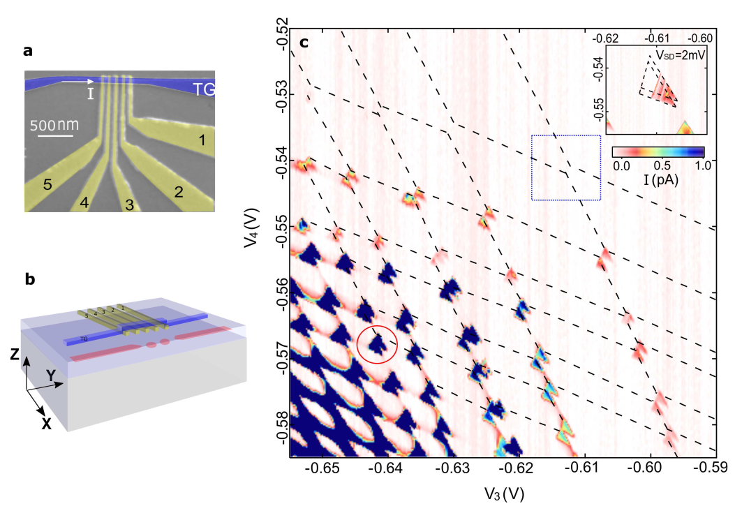
The operation of a few-hole double quantum dot. To reach the few-hole limit we use a quantum dot device with the double-layer-gate design 18 shown in Figs 1(a) and (b). The operation of the double dot is demonstrated by the charge stability diagram shown in Fig 1(c). The size of the honeycombs increases rapidly as gate biases V3 and V4 are made more positive, which suggests the dots are in the few-hole regime. The measured addition energy of E meV for the second hole in both dots is also comparable to measurements with the same device in a single-dot configuration. For the last row of bias triangles the current is very small due to imbalanced tunnel barriers. We plot in the inset of Fig 1(c) the last observable pair of bias triangles with V mV. The strong suppression of ISD in the base of these triangles explains why they were not visible with V mV.
Pauli spin blockade. Signatures of Pauli spin blockade are observed in several pairs of bias triangles with different hole occupations, and here we focus on the bias triangles highlighted by the red circle in Fig 1(c). Figs 2(a) and (b) show a zoom-in of the region around these bias triangles for positive and negative VSD. Comparing the two figures, the top and bottom pairs of bias triangles look very similar, whereas the current through the base of the middle pair of bias triangles (highlighted by the black arrows) is strongly suppressed in the positive-bias direction but flows freely in the negative-bias direction. This is a characteristic signature of Pauli spin blockade, as illustrated in the schematics in Fig 2(c) and (d). Current is suppressed in the positive-bias direction as transport through the only energetically allowed S(0, 2) singlet state is blocked when a T(1, 1) triplet state is occupied. The bias at which Pauli spin blockade is lifted gives the singlet-triplet splitting 150 eV.
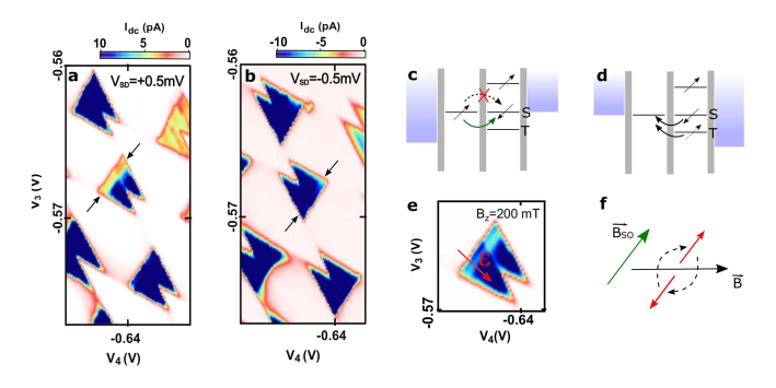
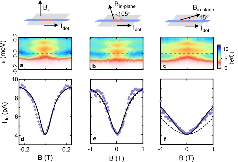
In addition to the dependence of ISD on bias direction, another signature of Pauli spin blockade is the effect of a magnetic field. As shown in Fig 2(e), applying a small perpendicular magnetic field of B mT almost fully recovers the current through the spin blocked region. In GaAs hole systems, the strong spin-orbit interaction (SOI) leads to hybridization of the triplet and the singlet states, which allows the previously forbidden transition and lifts the spin blockade at finite B. In the simple physical picture shown in Fig 2(f), spins are oriented along the intrinsic effective spin-orbit field direction , so that an external magnetic field applied perpendicular to causes the spin to precess around . This rotates the spin and enables spin-flip tunnelling to lift the spin blockade. The detailed response of the leakage current induced by SOI is shown in Fig 3(a) as a function of detuning and Bz, and a linecut at zero-detuning is plotted in Fig 3(d). The current in the spin-blocked region increases monotonically as the field increases, until it reaches the value of the non-blocked case.
A more interesting situation is when an in-plane magnetic field is applied, since the orientation of always points in the plane of charge motion and depends strongly on the nature of the dominant SOI. For a heavy-hole system, Rashba SOI creates an effective perpendicular to , which can be simply considered as the current direction or the double-dot axis. On the other hand, if Dresselhaus SOI is dominant, depends on the crystalline orientation and is parallel to for heavy-holes in (100) GaAs (see Supplementary information S3). Therefore, to gain more information about the SOI in our device, we plot in Figs 3(b) and (c) the leakage current when an in-plane magnetic field is applied along two orthogonal directions. Even though a similar zero-field dip is observed for both cases, the widths of the dip are dramatically different. A full recovery of the spin-blocked current occurs at T when the field is roughly perpendicular to the double-dot axis, whereas when the magnetic field is applied roughly parallel to the double-dot axis, no saturation of dot current is observed up to 1 T.
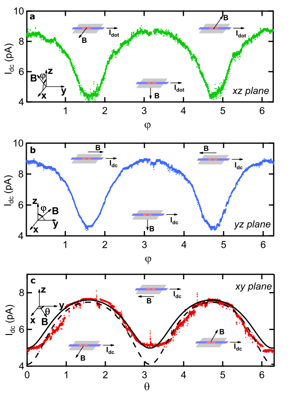
To systematically investigate the anisotropy of the lifting of spin blockade, a fixed magnetic field is rotated in the , and planes, while monitoring the current through the double dot in the spin-blocked regime. Figs 4(a) and Fig 4(b) show the leakage current at zero-detuning as a fixed magnetic field T is rotated in the and planes, and Fig 4(c) shows what happens when the magnetic field is rotated in the plane (using a slightly larger field of 0.5 T).
As most theoretical studies of Pauli spin blockade have focussed on spin-1/2 electrons 19, 6, to understand the anisotropy observed in our system, we follow the approach in Ref. 19 and calculate heavy-hole transport through a double quantum dot in the presence of strong SOI. We start with a Hamiltonian including Zeeman, Dresselhaus and Rashba SOI terms. Assuming heavy-hole light-hole mixing is small enough to be considered as a perturbation, we numerically evaluate the spin-conserving and spin-flipping tunnelling matrix elements between all (1, 1) states and the (0, 2) singlet. The resulting current through the double dot is dependent on both the hole g-factor (through the Zeeman effect) and the orientation of the external magnetic field relative to 20 (see Supplementary information S1 and S2). The measured current can be modelled with an interdot tunnel coupling eV, a ratio between spin-flipping and spin-conserving tunnelling processes, and a spin relaxation rate MHz, which is comparable to previous double-dot measurements 6, 14. The calculated current shows good qualitative agreement with the measurement, as depicted by the black lines in Figs 3(d) and (e). A small discrepancy between the calculation and the experiment appears when the magnetic field is almost parallel to the double-dot axis, shown by the dashed lines in Fig 3(f) and Fig 4(c). This small discrepancy can be accounted for by including a B-dependent spin relaxation process (B2) due to piezoelectric phonon coupling 21, 8, 22 (see Supplementary information S4). Fitting the data (solid line in Fig 3(f)) yields a B2-dependent spin relaxation rate of GHz at T. This implies a rather strong hole-phonon coupling, consistent with previous measurement of holes in GaAs 23. Note that SO-assisted relaxation due to phonon coupling is only visible when is aligned along the double-dot axis, as it only enhances the leakage current when the tunnelling rate induced by SOI is slow.
From the theoretical simulations the extreme anisotropy of the leakage current in Fig 4 can be understood as arising from two processes: firstly, when the magnetic field is tilted out-of-plane the Zeeman splitting between triplets increases dramatically due to the highly anisotropic heavy-hole g-factor in GaAs heterostructures 24, 25, which causes the anisotropic leakage current in Figs 4(a) and (b). Secondly, when the magnetic field is varied in-plane (Fig 4(c)), the relative orientation of with respect to changes, which affects the efficiency of the spin-flip tunnelling process. One extreme case is when is aligned with . In this case, no spin-flip tunnelling can be induced by SOI, so spin blockade persists and the current remains suppressed. Surprisingly, the minimum current of our device is observed when is applied the double-dot axis, which indicates that is parallel to the dot current. This result is very different from measurements on electron systems with strong SOI, where the suppression of current is observed when is applied to the double-dot axis 26. Our result is also distinct from previous studies of light-holes in nanowire dots, where no strong dependence of the current on the orientation of was observed 12. The difference in the orientation of between electrons, light-holes and heavy-holes highlights the fundamental differences between spin-1/2 and spin-3/2 systems. One possible explanation for the orientation of observed here is that the Dresselhaus SOI is much stronger than the Rashba SOI. This could be caused by the surface Dresselhaus SOI, which has been shown to be much larger than bulk Dresselhaus at a heterointerface 27. Alternatively, the orientation of could also be varied by transport through higher orbital excited states in elliptical quantum dots, although these should be energetically suppressed and in this case there would be no reason why should be aligned with the double-dot axis.
In conclusion, we present measurements of hole spin blockade in a double quantum dot. We observe a large increase in the leakage current when an external magnetic field is applied, which suggests the lifting of spin blockade due to SOI. By varying the magnetic field orientation, we demonstrate the anisotropic behaviour of the lifting of spin blockade. Intriguingly this anisotropy is very different to that observed for both electrons and light-holes. Numerical calculations yield quantitative agreement with experimental results, and suggest that the observed anisotropy can be due to a combination of the anisotropic hole g-factor and the Dresselhaus SOI.
Acknowledgements
This work was funded by the Australian Research Council under the DP and DECRA schemes, and the EPSRC (UK). Devices were made at the NSW node of the Australian National Fabrication Facility. We thank O. Sushkov, D. Miserev, M. V. Durnev, L. E. Golub and A. Sachrajda for helpful discussions.
References
References
- 1 Nadj-Perge, S.; Frolov, S. M.; Bakkers, E. P. A. M.; Kouwenhoven, L. P. Nature 2010, 468, 1084 – 1087
- 2 van den Berg, J. W. G.; Nadj-Perge, S.; Pribiag, V. S.; Plissard, S. R.; Bakkers, E. P. A. M.; Frolov, S. M.; Kouwenhoven, L. P. Phys. Rev. Lett. 2013, 110, 066806
- 3 Flindt, C.; Sørensen, A. S.; Flensberg, K. Phys. Rev. Lett. 2006, 97, 240501
- 4 Pfund, A.; Shorubalko, I.; Ensslin, K.; Leturcq, R. Phys. Rev. Lett. 2007, 99, 036801
- 5 Schroer, M. D.; Petersson, K. D.; Jung, M.; Petta, J. R. Phys. Rev. Lett. 2011, 107, 176811
- 6 Nadj-Perge, S.; Frolov, S. M.; van Tilburg, J. W. W.; Danon, J.; Nazarov, Y. V.; Algra, R.; Bakkers, E. P. A. M.; Kouwenhoven, L. P. Phys. Rev. B 2010, 81, 201305(R)
- 7 Jouravlev, O. N.; Nazarov, Y. V. Phys. Rev. Lett. 2006, 96, 176804
- 8 Bulaev, D. V.; Loss, D. Phys. Rev. Lett. 2005, 95, 076805
- 9 Fischer, J.; Coish, W. A.; Bulaev, D. V.; Loss, D. Phys. Rev. B 2008, 78, 155329
- 10 Fischer, J.; Loss, D. Phys. Rev. Lett. 2010, 105, 266603
- 11 Chekhovich, E. A.; Makhonin, M. N.; Tartakovskii, A. I.; Yacoby, A.; Bluhm, H.; Nowack, K. C.; Vandersypen, L. M. K. Nat Mater 2013, 12, 494 – 504
- 12 Pribiag, V. S.; Nadj-Perge, S.; Frolov, S. M.; van den Berg, J. W. G.; van Weperen, I.; Plissard, S. R.; Bakkers, E. P. A. M.; Kouwenhoven, L. P. Nat Nanotechnol 2013, 8, 170 – 174
- 13 Higginbotham, A. P.; Larsen, T. W.; Yao, J.; Yan, H.; Lieber, C. M.; Marcus, C. M.; Kuemmeth, F. Nano Lett. 2014, 14, 3582 – 3586
- 14 Li, R.; Hudson, F. E.; Dzurak, A. S.; Hamilton, A. R. Nano Lett. 2015, 15, 7314 – 7318
- 15 Takakura, T.; Noiri, A.; Obata, T.; Otsuka, T.; Yoneda, J.; Yoshida, K.; Tarucha, S. Appl. Phys. Lett. 2014, 104, 113109
- 16 Ward, D. R.; Kim, D.; Savage, D. E.; Lagally, M. G.; Foote, R. H.; Friesen, M.; Coppersmith, S. N.; Eriksson, M. A. arXiv:1604.07956 2016,
- 17 Hanson, R.; Kouwenhoven, L. P.; Petta, J. R.; Tarucha, S.; Vandersypen, L. M. K. Rev. Mod. Phys. 2007, 79, 1217–1265
- 18 Wang, D. Q.; Hamilton, A. R.; Farrer, I.; Ritchie, D. A.; Klochan, O. Nanotechnology 2016, 27, 334001
- 19 Danon, J.; Nazarov, Y. V. Phys. Rev. B 2009, 80, 041301R
- 20 Hung, J.-T.; Marcellina, E.; Wang, B.; Hamilton, A. R.; Culcer, D. arXiv:1610.02119 2016,
- 21 Baruffa, F.; Stano, P.; Fabian, J. Phys. Rev. Lett. 2010, 104, 126401
- 22 Bulaev, D. V.; Loss, D. Phys. Rev. Lett. 2007, 98, 097202
- 23 Gao, X. P. A.; Boebinger, G. S.; Mills, A. P.; Ramirez, A. P.; Pfeiffer, L. N.; West, K. W. Phys. Rev. Lett. 2005, 94, 086402
- 24 Winkler, R. Springer-Verlag Berlin Heidelberg 2003,
- 25 Simion, G. E.; Lyanda-Geller, Y. B. Phys. Rev. B 2014, 90, 195410
- 26 Nadj-Perge, S.; Pribiag, V. S.; van den Berg, J. W. G.; Zuo, K.; Plissard, S. R.; Bakkers, E. P. A. M.; Frolov, S. M.; Kouwenhoven, L. P. Phys. Rev. Lett. 2012, 108, 166801
- 27 Durnev, M. V.; Glazov, M. M.; Ivchenko, E. L. Phys. Rev. B 2014, 89, 075430