Domain wall profiles in Co/Irn/Pt(111) ultrathin films: influence of the Dzyaloshinskii-Moriya interaction
Abstract
We perform a study of domain walls in Co/Irn/Pt(111) () films by a combined approach of first-principles calculations and spin dynamics simulations. We determine the tensorial exchange interactions and the magnetic anisotropies for the Co overlayer in both FCC and HCP geometries, depending on the number of Ir buffer layers. We find strong ferromagnetic nearest-neighbor isotropic exchange interactions between the Co atoms and an out-of-plane magnetic anisotropy for the films in FCC geometry. Our simulations show that the magnetic domain walls are of Néel type, and their rotational sense (chirality) is changed upon the insertion of an Ir buffer layer as compared to the pristine Co/Pt(111) system. Our spin dynamics simulations indicate a twisting of the spins with respect to the planar domain wall profile on the triangular lattice. We discuss this domain wall twisting using symmetry arguments and in terms of an appropriate micromagnetic continuum model considering extra energy terms compared to the available literature.
I Introduction
Effective spin models are widely used to investigate the magnetic properties of solids. The breaking of inversion symmetry in noncentrosymmetric crystals, at surfaces or interfaces and the presence of the spin–orbit coupling lead to the appearance of an anisotropic exchange term beyond the isotropic Heisenberg interaction, which is known as the Dzyaloshinskii-Moriya (DM) interactionDzyaloshinsky (1958); Moriya (1960). In collinear ferromagnetic systems, this type of interaction provides domain walls (DWs) with a chiral characterThiaville et al. (2012); Ryu et al. (2013); Chen et al. (2013a, b); von Bergmann et al. (2014); Tetienne et al. (2015), plays a key role in DW dynamicsMoore et al. (2008); Je et al. (2013); Emori et al. (2013); Lo Conte et al. (2015), and leads to the stabilization of isolated chiral skyrmionsBogdanov and Hubert (1994a); Nagaosa and Tokura (2013); Rohart and Thiaville (2013); Romming et al. (2013). It may also cause the formation of noncollinear magnetic statesvon Bergmann et al. (2014); Honolka et al. (2009) such as spin spiralsBode et al. (2007); Meckler et al. (2009) and condensated skyrmionic phasesRößler et al. (2006); Mühlbauer et al. (2009); Yu et al. (2010); Heinze et al. (2011); Romming et al. (2013); Simon et al. (2014). Furthermore, the DM interaction induces an asymmetry in the spin wave spectrum of thin ferromagnetic filmsUdvardi and Szunyogh (2009); Cortés-Ortuño and Landeros (2013). Based on this asymmetry, recently extensive experimental efforts have been directed towards the measurement of the interfacial DM interaction by using inelastic light scatteringBelmeguenai et al. (2015); Cho et al. (2015); Kim et al. (2015), highly resolved spin-polarized electron energy lossZakeri et al. (2010) or propagating spin wave spectroscopyLee et al. (2016).
The current-driven motion of domain walls is mainly investigated in ultrathin films and multilayers, paving the way for future applications in spintronic and logic devicesAllwood et al. (2005); Parkin et al. (2008). In these systems, heavy nonmagnetic elements provide the strong spin–orbit coupling necessary for the appearance of the DM interaction in the adjacent magnetic layers. Using the micromagnetic energy functional determined by DzyaloshinskiiDzyaloshinsky (1965), it has been demonstratedBogdanov and Hubert (1994b); Heide et al. (2008); Thiaville et al. (2012) that the DM interaction prefers a cycloidal or Néel-type rotation of spins within a domain wall in the symmetry class to which the majority of these systems belong. The rotational plane of domain walls is determined by the competition between the DM interaction and the magnetostatic dipolar interaction preferring a helical or Bloch-type rotationThiaville et al. (2012), while the right- or left-handed chirality is determined by the sign of the DM interaction. Recently a significant research effort has been devoted to examine the connection between the nonmagnetic material composition and the sign and magnitude of the DM interaction, both based on experimental observationsRyu et al. (2013, 2014); Chen et al. (2013a); Lee et al. (2016); Hrabec et al. (2014) and first-principles electronic structure calculationsYang et al. (2015). In Ref. Hrabec et al. (2014), Pt/Co/Pt and Pt/Co/Ir/Pt multilayers with different Ir thicknesses were studied using a field-driven domain wall creep-based method. It was demonstrated that due to the insertion of the Ir layer, the chirality of the Néel wall reversed from right-handed to left-handed, which was attributed to the sign change of the effective DM interaction.
Motivated by the experimental study in Ref. Hrabec et al. (2014), in this work we investigate the magnetic properties of Co/Pt(111) and Co/Irn/Pt(111) () films. We use first-principles electronic structure calculation methods to determine the parameters in a spin model where the coupling between the spins is described by an exchange interaction tensorUdvardi et al. (2003), and perform atomistic spin dynamics calculations in order to determine the domain wall profiles. We give direct evidence of the relationship between the homochirality of the Néel DWs and the calculated DM vectors, confirming the reversal of the DW chirality by inserting the Ir layer between the Co monolayer and the Pt substrate. Moreover, we observe that the presence of the Ir layers weakens the ferromagnetic exchange coupling between the neighboring Co atoms and increases the magnetic anisotropy, thus the DWs become more narrow. We also observe a small twisting of the spins in the DW, leading to a non-coplanar DW profile. Using symmetry arguments we attribute the appearance of this twisting to the out-of-plane components of the DM vectors and a specific term appearing in the symmetric off-diagonal part of the interaction tensors. We explain how the appearance of the twisting depends on the DW normal vector direction, and construct an appropriate micromagnetic continuum model, where the direction and shape of the twisting depends on the coefficients corresponding to the out-of-plane component of the DM vector and the symmetric off-diagonal interaction.
II Computational method
We performed self-consistent electronic structure calculations for the Co/Irn/Pt(111) () ultrathin films in terms of relativistic screened Korringa–Kohn–Rostoker (SKKR) methodSzunyogh et al. (1994); Zeller et al. (1995). We used the local spin density approximation parametrized by Vosko et al.Vosko et al. (1980) and the atomic sphere approximation with an angular momentum cutoff of . The system consisted of Pt and Ir atomic layers (), a Co monolayer and monolayers of vacuum (empty spheres) between the semi-infinite Pt substrate and semi-infinite vacuum. For modeling the geometry of the thin films we used the value for the in-plane lattice constant of the Pt surface, and we optimized the distance between the layers in terms of VASP calculationsKresse and Furthmüller (1996a, b); Hafner (2008) for both FCC and HCP stackings of the Co overlayer. We found an inward relaxation of the Co overlayer between 11 and 14% relative to the Pt-Pt bulk interlayer distance, depending on the number of Ir buffer layers. These inward layer relaxations were used in the self-consistent SKKR calculations, and the Wigner–Seitz radii of the Co, Ir, and top Pt layers were modified according to the relaxations.
We described the localized magnetic moments in the Co layer in terms of a generalized classical Heisenberg model of the form
| (1) |
where denotes the spin unit vector at site , is the exchange coupling tensorUdvardi et al. (2003), and is the on-site anisotropy matrix. The corresponding parameters of the spin model in Eq. (1) were determined by combining the SKKR method with the relativistic torque techniqueUdvardi et al. (2003); Ebert and Mankovsky (2009), based on calculating the energy costs of infinitesimal rotations around ferromagnetic states oriented along different crystallographic directions. We considered the out-of-plane ferromagnetic state and orientations along three nonparallel in-plane nearest-neighbor directions, sufficient for reproducing the symmetry of the system in the interaction tensors. The energy integrals were performed by sampling 16 points on a semicircle contour in the upper complex semi-plane. We have calculated the interactions with neighbors within a radius of , for a total of 90 neighbors.
The interaction tensor may be decomposed as
| (2) |
i.e. into an isotropic, an antisymmetric and a traceless symmetric part. The first term represents the scalar Heisenberg couplings between the magnetic moments, with . The three components of the antisymmetric part of the exchange tensor can be identified with the DM vector , defined as
| (3) |
The traceless symmetric part contains five components in the general case; its diagonal terms induce an energy difference between the uniformly magnetized states along the out-of-plane () and in-plane () directions, , which we will refer to as the two-site magnetic anisotropy. In the symmetry class, the on-site anisotropy tensor may be described by a single parameter,
| (4) |
The total magnetic anisotropy energy (MAE) of the system can be expressed as a sum of the on-site and two-site contributions, .
In order to determine the equilibrium DW profile, we performed spin dynamics simulations by numerically solving the deterministic Landau–Lifshitz–Gilbert equationLandau and Lifshitz (1935); Gilbert (1956),
| (5) |
with the Gilbert damping parameter and , where is the gyromagnetic ratio (, and standing for the electron factor, absolute charge, and mass). The spin model parameters from Eq. (1) enter into the effective field , which governs the time evolution of the spins. The spin magnetic moment was determined from the electronic structure calculations, taking values between and depending on the number of Ir layers and FCC or HCP stacking.
III Results and discussion
III.1 Spin model parameters
Figure 1 displays the calculated isotropic exchange constants between the Co atoms as a function of the interatomic distance for FCC and HCP stackings, for different numbers of Ir buffer layers.
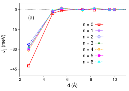
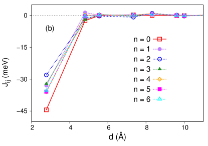
Because of the sign convention of Eq. (1), the negative sign of the isotropic exchange parameter means ferromagnetic (FM) coupling, while the positive sign refers to antiferromagnetic (AFM) interaction. For both types of stacking, the nearest-neighbor (NN) interactions are strongly FM; for larger interatomic distances the interactions are mostly negligible due to the rapid decay. The NN coupling is the strongest for Co/Pt(111), and in FCC and HCP stacking, respectively. The presence of Ir layers considerably reduces the NN coupling, which is almost independent of the number of buffer layers for FCC stacking (between and ), while in the case of the HCP stacking this range is somewhat wider (between and ).
We have summarized the on-site, two-site, and total magnetic anisotropies for the Co monolayer in Table 1, considering both types of stacking.
| FCC | HCP | |||||
|---|---|---|---|---|---|---|
| MAE | MAE | |||||
| 0 | 0.40 | -0.20 | 0.20 | 0.46 | 0.10 | 0.57 |
| 1 | 1.02 | 1.63 | 2.64 | 1.17 | 1.41 | 2.58 |
| 2 | 0.77 | 1.01 | 1.77 | 0.31 | -0.38 | -0.06 |
| 3 | 0.31 | 0.60 | 0.91 | -0.06 | -0.87 | -0.93 |
| 4 | 0.82 | 0.56 | 1.39 | 0.70 | 0.02 | 0.72 |
| 5 | 0.87 | 1.66 | 2.53 | 0.81 | 0.36 | 1.17 |
| 6 | 0.75 | 1.71 | 2.46 | 0.57 | 0.25 | 0.82 |
With our definition the positive sign of the on-site and two-site magnetic anisotropies corresponds to an easy axis along the out-of-plane () direction. It can be seen from Table 1 that most of the samples have an out-of-plane easy axis. For FCC stacking, the Ir buffer layer clearly enhances the magnetic anisotropy, which seems to saturate at around for larger . For HCP stacking, an Ir monolayer also remarkably increases the perpendicular MAE. In the case of two and three Ir atomic layers we, however, observe easy-plane anisotropy, while for thicker Ir layers it is again of easy-axis type. This oscillation of the sign of the MAE is similar to the effect recently found in Mn/Wm/Con/W multilayersNandy et al. (2016), and can most likely be attributed to interface-induced Friedel oscillations.
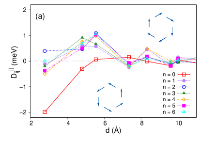
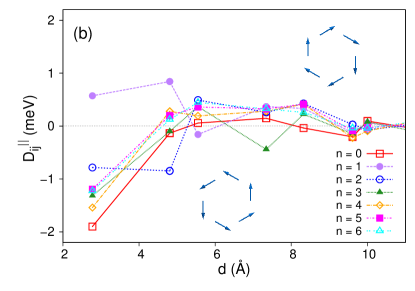
Next we investigate the in-plane component of the DM vectors, , between the Co atoms for FCC and HCP stacking geometries, since this component is related to the strength of the scalar DM interaction in micromagnetic models, see Ref. Yang et al. (2015) and Appendix A. The sign of corresponds to the rotational direction of the DM vectors in a given shell of neighbors as illustrated in Fig. 2. In case of Co/Pt(111), for the NN‘s with the value of for the FCC stacking and for the HCP stacking are the most significant, and they rotate in counter-clockwise direction. For Co/Irn/Pt(111) () layers with FCC stacking geometry the magnitude of the NN in-plane DM vectors is much smaller than for Co/Pt(111), and for the second and third neighbors dominate with a clockwise rotational direction, denoted by a positive sign in Fig. 2(a). This clearly implies a sign change of the effective scalar DM interaction when adding Ir layers between the Pt and Co layers, similarly to the recent experimentalHrabec et al. (2014) as well as theoretical findingsYang et al. (2015). In case of HCP stacking geometry (see Fig. 2(b)), for Co/Ir1/Pt(111) the first- and second-neighbor in-plane DM vectors dominate with approximately the same magnitude and rotating in a clock-wise direction, i.e. the sign change of the scalar DM interaction is present. For thicker Ir layers, the NN with relatively large magnitude turns to counter-clockwise direction, while the magnitude and direction of show an oscillating behavior against both the distance between the Co atoms and the number of Ir layers.
From the calculated spin model parameters, it can be concluded that the magnetic anisotropy and the DM vectors strongly depend on the stacking geometry. We attribute the high sensitivity of the interactions induced by spin–orbit coupling to the different hybridization between the electronic states of the Co monolayer and the adjacent Ir layer for the different stackings. Similar effects related to the stacking geometry have been reported experimentally for a Mn monolayer on Ag(111)Gao et al. (2008) or Fe/Ir(111)von Bergmann et al. (2015), and computationally for Cr/Au(111)Balogh et al. (2014) or for Pd/Fe/Ir(111)Dupé et al. (2014). Since in the FCC geometry the system is perpendicularly magnetized regardless of the thickness of the Ir buffer layer, which corresponds to the experimental situationHrabec et al. (2014), in the next sections we focus on the domain wall formation in the Co/Pt(111) and Co/Irn/Pt(111) films only in case of FCC stacking.
III.2 Domain wall formation and chirality
By using the spin model parameters obtained from first principles, we performed spin dynamics simulations for determining the equilibrium DW profiles in the system. We have used a lattice consisting of spins, and set the normal vector of the DW along the direction connecting two NN sites on a triangular lattice, which will correspond to the axis of the coordinate system. The perpendicular direction connecting next-nearest neighbors and falling in the symmetry plane of the system will be denoted by . During the simulations we fixed the spins along the and out-of-plane directions at the two edges of the lattice in the direction, and periodic boundary conditions have been applied along the perpendicular direction. We have initialized a system in a non-optimized DW configuration, and minimized the energy by numerically solving Eq. (5) with high damping, .
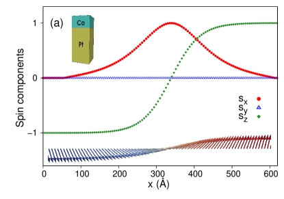
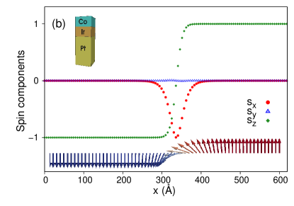
The simulated DW profiles are shown for Co/Pt(111) and Co/Ir1/Pt(111) films for the FCC stacking of the Co layer in Fig. 3. The DWs are visibly of Néel type, since the magnitude of the in-plane component parallel to the propagation direction increases from at the edge of the sample to at the center of the wall (), while the component remains close to zero, indicating a rotation in the plane. It is known from micromagnetic theoryLandau and Lifshitz (1935); Heide et al. (2008) that the DW width is proportional to , where the exchange stiffness is connected to the Heisenberg exchange in our description, while the anisotropy constant corresponds to the MAE. This explains why the width of the DW significantly decreases with the addition of the Ir buffer layer: the NN Heisenberg exchange interaction weakens (see Fig. 1), while the MAE increases (see Table 1).
It can also be seen in Fig. 3 that the rotational sense of the Néel DW switches from left-handed in Co/Pt(111) to right-handed in Co/Ir1/Pt(111), indicated by the sign change of the spin component with a fixed sign of . This is connected to the sign of the in-plane component of the DM vectors in Fig. 2: negative and positive signs prefer left- and right-handed rotations, respectively. In the experimental observations of Ref. Hrabec et al. (2014), the rotational sense of the DWs switched from right-handed to left-handed when the Ir buffer layer was introduced between the Co layer and the Pt layer on top of it. The chirality is in agreement with our calculations if we take into account that we have introduced the Ir buffer layer below the Co layer, because swapping the up and down directions also switches the notion of left- and right-handed rotationsHeide et al. (2008). Our simulations confirmed that by further increasing the number of Ir layers the right-handed DW chirality is preserved, and the DW width is less sensitive to this change. Again these observations are in agreement with the arguments given above and the model parameters discussed in Sec. III.1.
We also performed the simulations by including the magnetostatic dipolar interaction in Eq. (1). We have included dipolar coupling between neighbors within a radius of , which accounts for about of the total strength of this long-ranged interaction in the considered monolayer system. One effect of the dipolar interaction was decreasing the MAE values listed in Table 1 by approximately ; however, this does not switch between easy-axis and easy-plane anisotropy in any of the considered cases. Furthermore, it is known from the literatureBogdanov and Hubert (1994a); Thiaville et al. (2012) that the rotational plane of the DW assumes an intermediate state between Bloch- and Néel-type rotation if the dipolar interaction is present in the system and the in-plane component of the DM interaction is weaker than a threshold value. However, we have confirmed with simulations that in the considered systems the DM interaction is about ten times stronger than this threshold. Overall, it can be concluded that the dipolar interaction only slightly modifies the DW width in the system, therefore, it can safely be neglected.
III.3 Atomistic simulations of domain wall twisting
From the spin dynamics simulations we observed that the DW profile does not perfectly coincide with a planar Néel wall if the DW normal vector is along the NN direction. As demonstrated in Fig. 4, the spin component is also finite within the wall, and analogously to the component it changes sign in the middle of the DW. In the following we will refer this modulation of the DW as twisting of the spins. As illustrated in Fig. 4, the magnitude and also the exact shape of the twisting depends on the number of Ir buffer layers. However, even in the case of Co/Ir4/Pt where the largest twisting occurs, its peak value corresponds to only about 1% of the total length of the spin vectors.
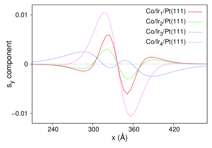
Note that this twisting is different from the rotation of the complete DW from the Néel-type towards the Bloch-type, which could occur due to the presence of the dipolar interaction as discussed at the end of Sec. III.2. In this case the component of the spin vectors would have a local maximum in the middle of the wall instead of a node. Furthermore, there is apparently no threshold value of the parameters for the occurrence of the twisting, in contrast to the rotation. Finally, we also observed that the twisting completely disappears if the normal vector of the DW is along the next-nearest-neighbor () direction, which would not happen in the case of rotation.
By considering symmetry arguments in the atomistic model it can be explained why the twisting occurs for DWs with normal vector along the direction, but not for ones with normal vector along the perpendicular direction. Considering a Néel DW with normal vector along the axis, the system may gain energy from tilting the spins towards the direction due to the and components of the interaction tensor in Eq. (1). As mentioned in Sec. II, the antisymmetric part of the tensor may be reformulated in the DM vector in Eq. (3). Analogously, from the symmetric part of the off-diagonal components we construct the in-plane vectors
| (6) |
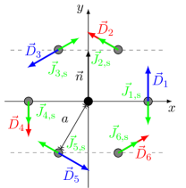
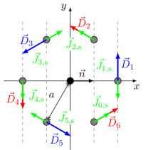
The DM vector transforms as an axial vector, while transforms as a two-dimensional polar vector under the planar symmetry operations. For the NNs these vectors are illustrated in Fig. 5. Due to the symmetry rules formulated by MoriyaMoriya (1960), the DM vector must be perpendicular to the lattice vector connecting the NNs; however, it may have an out-of-plane component, the sign of which is illustrated by red and blue colors in Fig. 5. Note that the out-of-plane component of the DM vectors is allowed specifically for surfaces in cubic systems with symmetry, but it disappears for or surfaces with and symmetriesCrépieux and Lacroix (1998). Since the component of the DM vector is connected to the tensor element, it may lead to a twisting of the spins. The staggered lines in Fig. 5 connect neighbors which are parallel to each other in the DW, for which the out-of-plane components of the DM vector appear additively in the energy expression. If the DW normal vector is in a symmetry plane (along the next-nearest-neighbor direction, Fig. 5(a)), the components exactly cancel, and no twisting occurs. However, the components are of the same sign for equivalent neighbors if the DW normal vector is along the NN direction (Fig. 5(b)).
Similarly, it can be shown that the vectors must be perpendicular to the NN lattice vectors. The twisting is caused by their components which is perpendicular to the normal vector of the Néel DW, corresponding to when the normal vector is along the direction and to for the normal vector along the direction. Similarly to the out-of-plane components of the DM vectors, the components of cancel for equivalent neighbors if the DW normal vector is along the direction (Fig. 5(a)), but they may lead to a twisting for DWs with normal vectors along the direction (Fig. 5(b)).
III.4 Continuum model of domain wall twisting
In order to get further insight into the formation of the twisting of DWs, we employed a micromagnetic model, where the magnetization is represented by the vector field with . The appropriate form of the micromagnetic functional containing exchange stiffness, magnetic anisotropy and (in-plane) DM interaction is known from the literatureDzyaloshinsky (1965); Heide et al. (2008). However, this model has to be extended by terms responsible for the observed twisting in the atomistic model, namely the out-of-plane component of the DM vector and the vector. The derivation of the appropriate functional in the two-dimensional plane based on symmetry considerations is given in Appendix A; here we restrict ourselves to the description of a DW with normal vector along the direction, which is perpendicular to the mirror plane of the system with symmetry. In this case, the energy expression simplifies to a one-dimensional integral,
| (7) |
where denotes differentiation with respect to the variable . corresponds to the exchange stiffness, to the linear Lifshitz invariant or DM interaction, and to the anisotropy. Note that although the equivalent of the component of the DM vector is antisymmetric in the spin components as expected, it only appears in a term proportional to the third derivative of the field . Finally, the appropriate form of the off-diagonal tensor elements appearing in the vector is analogous to the exchange stiffness.
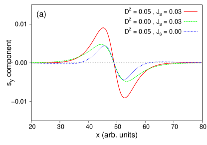
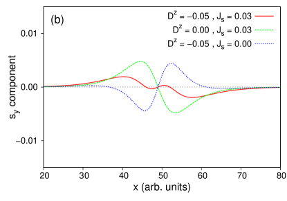
We have determined the equilibrium domain wall profile by rewriting Eq. (7) into spherical coordinates for the spin field, and numerically solving the Euler–Lagrange equations with the boundary conditions corresponding to a Néel DW – see Appendix B for the derivation. The twisting obtained from the numerical solution for specific parameter sets is illustrated in Fig. 6, by using dimensionless ferromagnetic coupling , easy-axis anisotropy , and DM interaction , the latter being responsible for fixing the right-handed Néel rotation of the DW observed in the spin dynamics simulations for Co/Irn/Pt(111). In the absence of the and terms, it is known that all domain wall profiles are equivalent under an appropriate rescaling of the length unitHeide et al. (2008). This is no longer the case here; it can be seen in Fig. 6 that if is finite, then the component changes sign in the middle of the DW, while for further sign changes may occur away from the center. If the sign of and is the same (Fig. 6(a) solid curve), the two types of twisting add up, for a net effect that is similar to the one observed for Co/Ir4/Pt(111) in Fig. 4. For different signs (Fig. 6(b) solid curve), it is possible that the twisting almost disappears around the middle of the DW, similarly to the case of Co/Ir3/Pt(111) in Fig. 4. It should be noted that further DW twisting shapes may be obtained by modifying the ratio of and besides their sign.
IV Conclusion
In summary, we examined the Co/Irn/Pt () ultrathin films by a combined approach of first-principles calculations and spin dynamics simulations. We determined the Co-Co magnetic exchange interaction tensors between different pairs of neighbors and the magnetic anisotropies for FCC and HCP growth of the Co overlayer, depending on the number of the Ir buffer layers. We found strong nearest-neighbor ferromagnetic isotropic exchange interactions in the Co layer and an easy-axis out-of-plane anisotropy for the films in FCC geometry, independent from their thickness. Our simulations have proven that the system prefers Néel walls over Bloch walls and, in agreement with related experimentsHrabec et al. (2014), the chirality of the Néel walls switches from left-handed to right-handed when the Ir layer is inserted between the Co monolayer and the Pt substrate. Both facts were uniquely attributed to the in-plane components of the Dzyaloshinskii-Moriya vectors, emphasizing that nearest-neighbor in-plane DM vectors dominate in the Co/Pt(111) system, whereas for Co/Irn/Pt(111) the second- and third-neighbor in-plane DM vectors are the largest ones. Furthermore, we have found that the width of domain walls is significantly smaller in the presence of the Ir buffer layers, owing to the decreased ferromagnetic isotropic exchange interactions and the increased magnetic anisotropy energy.
We also demonstrated the existence of a twisted domain wall profile, where the spins are not perfectly coplanar as in the ideal Néel wall. This effect was attributed to the out-of-plane component of the Dzyaloshinskii-Moriya vectors, which are not forbidden by symmetry in the triangular lattice on the surfaces of cubic lattices, and to the vectors constructed from the symmetric off-diagonal part of the interaction tensor. Based on symmetry arguments we have shown that the twisting must disappear if the normal vector of the DW is within the mirror plane of the system, but it is present for arbitrarily small values of these specific interaction coefficients if the normal vector is perpendicular to the mirror plane. We managed to qualitatively reproduce the different twisting lineshapes observed for different numbers of Ir buffer layers by constructing an appropriate micromagnetic model containing the out-of-plane component of the Dzyaloshinskii-Moriya vectors and the vectors.
Acknowledgements.
Financial support of the National Research, Development and Innovation Office of Hungary under Projects No. K115575 and No. PD120917 is gratefully acknowledged. K.P. acknowledges the SASPRO Fellowship of the Slovak Academy of Sciences (Project No. 1239/02/01).Appendix A Construction of the continuum model
In this Appendix we derive the energy functional Eq. (7) used for the description of twisted DWs by starting from the atomistic model. First we consider the exchange interaction tensor between two NNs displaced along the axis. In the symmetry class of the system, mirror planes connect next-nearest neighbors, and they go through the center of the line connecting the NNs, see Fig. 5(b). Mirroring the system switches the spins and and also transforms them as axial vectors. Due to this symmetry, both the and vectors must lie in the mirror plane. This simplifies the form of the interaction tensor to
| (11) |
which has 6 independent components. The possible rotations do not decrease the number of independent components further. The interaction tensors with the other 5 nearest neighbors can be obtained by performing the necessary symmetry operations.
For constructing the continuum model, one has to replace the spin vectors by the field , expand the spins at the neighboring lattice sites in Taylor series,
| (12) |
then perform the summation over the NNs. For every independent component in Eq. (11), we truncated the Taylor series at the first nonvanishing finite derivative. This leads to the energy expression
| (13) |
where the notation denotes that the energy densities are expressed for a two-dimensional system. The final form of Eq. (7) is obtained after simplifying Eq. (13) to one spatial dimension, where it is assumed that the spins are parallel when the integration is performed along the direction.
The first term in Eq. (13), corresponding to the exchange stiffness, reads
| (14) |
which is obtained from the isotropic exchange interactions or the related coefficient in Eq. (11). Note that denotes ferromagnetic coupling in this expression.
The anisotropy term is
| (15) |
which contains contributions from the on-site anisotropy term Eq. (4), as well as the leading-order corrections from the coefficients and ; see the two-site magnetic anisotropy defined in Sec. II. We mention that , known as the compass anisotropyNussinov and van den Brink (2015), also leads to a term that prefers Bloch DWs for when it is expanded up to second-order spatial derivatives. This is analogous to the role of the magnetostatic dipolar interaction; however, as it was discussed in Sec. III.2 the rotation of the DW from Néel-type towards Bloch-type is a threshold effect, and we have not observed it during the simulations. Therefore, we have not included the term related to in the energy functionals Eq. (7) and Eq. (11), used for the description of the DW twisting.
The DM interaction or linear Lifshitz invariant reads
| (16) |
and it is obtained from the in-plane components of the DM vectors .
Since Eq. (16) is the only expression containing first-order derivatives allowed in the symmetry classBogdanov and Yablonskiĭ (1989), the out-of-plane component of the DM vectors may only show up in the form of higher-order derivatives. The leading contribution is
| (17) |
The last term in Eq. (13) reads
| (18) |
which contains the contributions from the interaction coefficients in the discrete model.
The following symmetry argument proves why during the twisting a node of the spin component appears at the center of the DW. As it can be seen in Fig. 3, the out-of-plane component of the spins is an odd function of the distance from the center of the wall, corresponding to a function in the ideal caseLandau and Lifshitz (1935). On the other hand, the in-plane component is an even function, ideally . The system may gain energy from in Eq. (17) or in Eq. (18) if the energy densities are even functions, since integrating over an odd function yields zero. In both cases this means that the component must be an odd function, in agreement with the simulational observations. Such a twisting is energetically preferable for an arbitrarily small value of these interaction coefficients, in contrast to the rotation towards the direction of the Bloch-type DW; this can be demonstrated by constructing the Euler–Lagrange equations (27)-(28) given in Appendix B below.
From Eqs. (17)-(18) it can also be seen why the twisting disappears for Néel-type DWs with normal vector along the direction. The term Eq. (17) exactly cancels when the normal vector of the wall is along the direction. In the case of , it will still contain only the and spin components as in Eq. (7). Consequently, it can only induce a twisting if originally the spins in the domain wall lie in the plane, which corresponds to a Bloch DW with normal vector along the direction. For completeness, we mention that also induces a twisting for Bloch DWs with normal vector along the direction, but the term only induces a twisting for Néel-type DWs oriented in this direction; for a summary see Table 2.
| normal vector | Bloch wall | Néel wall | Bloch wall | Néel wall |
|---|---|---|---|---|
| yes | yes | no | yes | |
| no | no | yes | no | |
Appendix B Euler–Lagrange equations
In order to determine the domain wall profile from Eq. (7), we represented the spin field in spherical coordinates,
| (19) |
where the different energy contributions may be expressed as
| (20) |
| (21) |
| (22) |
| (23) |
| (24) |
The equilibrium domain wall profile can be determined by solving the Euler–Lagrange equations corresponding to Eq. (7) using the general formulas
| (25) | ||||
| (26) |
appropriate for higher-order derivatives. This yields
| (27) | |||
| (28) |
The Euler–Lagrange equations were solved with the boundary conditions describing the right-rotating cycloidal Néel domain wall observed in the simulations in the presence of the Ir buffer layers, see Fig. 3(b). These correspond to as and as . By looking at the Euler–Lagrange equations it can clearly be seen that the perfect Néel shape cannot be an equilibrium solution for any finite value of or , and a twisting will occur.
References
- Dzyaloshinsky (1958) I. Dzyaloshinsky, J. Phys. Chem. Solids 4, 241 (1958).
- Moriya (1960) T. Moriya, Phys. Rev. Lett. 4, 228 (1960).
- Thiaville et al. (2012) A. Thiaville, S. Rohart, E. Jué, V. Cros, and A. Fert, Europhys. Lett. 100, 57002 (2012).
- Ryu et al. (2013) K.-S. Ryu, L. Thomas, S.-H. Yang, and S. Parkin, Nat. Nanotech. 8, 527 (2013).
- Chen et al. (2013a) G. Chen, T. Ma, A. T. N’Diaye, H. Kwon, C. Won, Y. Wu, and A. K. Schmid, Nat. Commun. 4, 2671 (2013a).
- Chen et al. (2013b) G. Chen, J. Zhu, A. Quesada, J. Li, A. T. N’Diaye, Y. Huo, T. P. Ma, Y. Chen, H. Y. Kwon, C. Won, Z. Q. Qiu, A. K. Schmid, and Y. Z. Wu, Phys. Rev. Lett. 110, 177204 (2013b).
- von Bergmann et al. (2014) K. von Bergmann, A. Kubetzka, O. Pietzsch, and R. Wiesendanger, J. Phys.: Condens. Matter 26, 394002 (2014).
- Tetienne et al. (2015) J.-P. Tetienne, T. Hingant, L. J. Martínez, S. Rohart, A. Thiaville, L. H. Diez, K. Garcia, J.-P. Adam, J.-V. Kim, J.-F. Roch, I. M. Miron, G. Gaudin, L. Vila, B. Ocker, D. Ravelosona, and V. Jacques, Nat. Commun. 6, 6733 (2015).
- Moore et al. (2008) T. A. Moore, I. M. Miron, G. Gaudin, G. Serret, S. Auffret, B. Rodmacq, A. Schuhl, S. Pizzini, J. Vogel, and M. Bonfim, Appl. Phys. Lett. 93, 262504 (2008).
- Je et al. (2013) S.-G. Je, D.-H. Kim, S.-C. Yoo, B.-C. Min, K.-J. Lee, and S.-B. Choe, Phys. Rev. B 88, 214401 (2013).
- Emori et al. (2013) S. Emori, U. Bauer, S.-M. Ahn, E. Martinez, and G. S. D. Beach, Nat. Mater. 12, 611 (2013).
- Lo Conte et al. (2015) R. Lo Conte, E. Martinez, A. Hrabec, A. Lamperti, T. Schulz, L. Nasi, L. Lazzarini, R. Mantovan, F. Maccherozzi, S. S. Dhesi, B. Ocker, C. H. Marrows, T. A. Moore, and M. Kläui, Phys. Rev. B 91, 014433 (2015).
- Bogdanov and Hubert (1994a) A. Bogdanov and A. Hubert, Phys. Stat. Sol. B 186, 527 (1994a).
- Nagaosa and Tokura (2013) N. Nagaosa and Y. Tokura, Nat. Nanotech. 8, 899 (2013).
- Rohart and Thiaville (2013) S. Rohart and A. Thiaville, Phys. Rev. B 88, 184422 (2013).
- Romming et al. (2013) N. Romming, C. Hanneken, M. Menzel, J. E. Bickel, B. Wolter, K. von Bergmann, A. Kubetzka, and R. Wiesendanger, Science 341, 636 (2013).
- Honolka et al. (2009) J. Honolka, T. Y. Lee, K. Kuhnke, A. Enders, R. Skomski, S. Bornemann, S. Mankovsky, J. Minár, J. Staunton, H. Ebert, M. Hessler, K. Fauth, G. Schütz, A. Buchsbaum, M. Schmid, P. Varga, and K. Kern, Phys. Rev. Lett. 102, 067207 (2009).
- Bode et al. (2007) M. Bode, M. Heide, K. von Bergmann, P. Ferriani, S. Heinze, G. Bihlmayer, A. Kubetzka, O. Pietzsch, S. Blügel, and R. Wiesendanger, Nature 447, 190 (2007).
- Meckler et al. (2009) S. Meckler, N. Mikuszeit, A. Preßler, E. Y. Vedmedenko, O. Pietzsch, and R. Wiesendanger, Phys. Rev. Lett. 103, 157201 (2009).
- Rößler et al. (2006) U. K. Rößler, A. N. Bogdanov, and C. Pfleiderer, Nature 442, 797 (2006).
- Mühlbauer et al. (2009) S. Mühlbauer, B. Binz, F. Jonietz, C. Pfleiderer, A. Rosch, A. Neubauer, R. Georgii, and P. Boni, Science 323, 915 (2009).
- Yu et al. (2010) X. Z. Yu, Y. Onose, N. Kanazawa, J. H. Park, J. H. Han, Y. Matsui, N. Nagaosa, and Y. Tokura, Nature 465, 901 (2010).
- Heinze et al. (2011) S. Heinze, K. von Bergmann, M. Menzel, J. Brede, A. Kubetzka, R. Wiesendanger, G. Bihlmayer, and S. Blügel, Nat. Phys. 7, 713 (2011).
- Simon et al. (2014) E. Simon, K. Palotás, L. Rózsa, L. Udvardi, and L. Szunyogh, Phys. Rev. B 90, 094410 (2014).
- Udvardi and Szunyogh (2009) L. Udvardi and L. Szunyogh, Phys. Rev. Lett. 102, 207204 (2009).
- Cortés-Ortuño and Landeros (2013) D. Cortés-Ortuño and P. Landeros, J. Phys.: Condens. Matter 25, 156001 (2013).
- Belmeguenai et al. (2015) M. Belmeguenai, J.-P. Adam, Y. Roussigné, S. Eimer, T. Devolder, J.-V. Kim, S. M. Cherif, A. Stashkevich, and A. Thiaville, Phys. Rev. B 91, 180405 (2015).
- Cho et al. (2015) J. Cho, N.-H. Kim, S. Lee, J.-S. Kim, R. Lavrijsen, A. Solignac, Y. Yin, D.-S. Han, N. J. J. van Hoof, H. J. M. Swagten, B. Koopmans, and C.-Y. You, Nat. Commun. 6, 7635 (2015).
- Kim et al. (2015) N.-H. Kim, D.-S. Han, J. Jung, J. Cho, J.-S. Kim, H. J. M. Swagten, and C.-Y. You, Appl. Phys. Lett. 107, 142408 (2015).
- Zakeri et al. (2010) K. Zakeri, Y. Zhang, J. Prokop, T.-H. Chuang, N. Sakr, W. X. Tang, and J. Kirschner, Phys. Rev. Lett. 104, 137203 (2010).
- Lee et al. (2016) J. M. Lee, C. Jang, B.-C. Min, S.-W. Lee, K.-J. Lee, and J. Chang, Nano Lett. 16, 62 (2016).
- Allwood et al. (2005) D. A. Allwood, G. Xiong, C. C. Faulkner, D. Atkinson, D. Petit, and R. P. Cowburn, Science 309, 1688 (2005).
- Parkin et al. (2008) S. S. P. Parkin, M. Hayashi, and L. Thomas, Science 320, 190 (2008).
- Dzyaloshinsky (1965) I. E. Dzyaloshinsky, Sov. Phys. JETP 20, 665 (1965).
- Bogdanov and Hubert (1994b) A. Bogdanov and A. Hubert, J. Magn. Magn. Mater. 138, 255 (1994b).
- Heide et al. (2008) M. Heide, G. Bihlmayer, and S. Blügel, Phys. Rev. B 78, 140403 (2008).
- Ryu et al. (2014) K.-S. Ryu, S.-H. Yang, L. Thomas, and S. S. P. Parkin, Nat. Commun. 5, 3910 (2014).
- Hrabec et al. (2014) A. Hrabec, N. A. Porter, A. Wells, M. J. Benitez, G. Burnell, S. McVitie, D. McGrouther, T. A. Moore, and C. H. Marrows, Phys. Rev. B 90, 020402 (2014).
- Yang et al. (2015) H. Yang, A. Thiaville, S. Rohart, A. Fert, and M. Chshiev, Phys. Rev. Lett. 115, 267210 (2015).
- Udvardi et al. (2003) L. Udvardi, L. Szunyogh, K. Palotás, and P. Weinberger, Phys. Rev. B 68, 104436 (2003).
- Szunyogh et al. (1994) L. Szunyogh, B. Újfalussy, P. Weinberger, and J. Kollár, Phys. Rev. B 49, 2721 (1994).
- Zeller et al. (1995) R. Zeller, P. H. Dederichs, B. Újfalussy, L. Szunyogh, and P. Weinberger, Phys. Rev. B 52, 8807 (1995).
- Vosko et al. (1980) S. H. Vosko, L. Wilk, and M. Nusair, Can. J. Phys. 58, 1200 (1980).
- Kresse and Furthmüller (1996a) G. Kresse and J. Furthmüller, Comput. Mater. Sci. 6, 15 (1996a).
- Kresse and Furthmüller (1996b) G. Kresse and J. Furthmüller, Phys. Rev. B 54, 11169 (1996b).
- Hafner (2008) J. Hafner, J. Comput. Chem. 29, 2044 (2008).
- Ebert and Mankovsky (2009) H. Ebert and S. Mankovsky, Phys. Rev. B 79, 045209 (2009).
- Landau and Lifshitz (1935) L. Landau and E. Lifshitz, Phys. Z. Sowjetunion 8, 153 (1935).
- Gilbert (1956) T. L. Gilbert, Ph.D. thesis (Illinois Institute of Technology, 1956).
- Nandy et al. (2016) A. K. Nandy, N. S. Kiselev, and S. Blügel, Phys. Rev. Lett. 116, 177202 (2016).
- Gao et al. (2008) C. L. Gao, W. Wulfhekel, and J. Kirschner, Phys. Rev. Lett. 101, 267205 (2008).
- von Bergmann et al. (2015) K. von Bergmann, M. Menzel, A. Kubetzka, and R. Wiesendanger, Nano Lett. 15, 3280 (2015).
- Balogh et al. (2014) L. Balogh, L. Udvardi, and L. Szunyogh, J. Phys.: Condens. Matter 26, 436001 (2014).
- Dupé et al. (2014) B. Dupé, M. Hoffmann, C. Paillard, and S. Heinze, Nat. Commun. 5, 4030 (2014).
- Crépieux and Lacroix (1998) A. Crépieux and C. Lacroix, J. Magn. Magn. Mater. 182, 341 (1998).
- Nussinov and van den Brink (2015) Z. Nussinov and J. van den Brink, Rev. Mod. Phys. 87, 1 (2015).
- Bogdanov and Yablonskiĭ (1989) A. N. Bogdanov and D. A. Yablonskiĭ, Sov. Phys. JETP 68, 101 (1989).