An Efficient Partial Sums Generator for Constituent Code based Successive Cancellation Decoding of Polar Codes
Abstract
This paper proposes the architecture of partial sum generator for constituent codes based polar code decoder. Constituent codes based polar code decoder has the advantage of low latency. However, no purposefully designed partial sum generator design exists that can yield desired timing for the decoder. We first derive the mathematical presentation with the partial sums set which is corresponding to each constituent codes. From this, we concoct a shift-register based partial sum generator. Next, the overall architecture and design details are described, and the overhead compared with conventional partial sum generator is evaluated. Finally, the implementation results with both ASIC and FPGA technology and relevant discussions are presented.
I Introduction
Recently, polar code [1] has received increasing attentions because it is the first code which provably achieves the channel capacity. Its low-complexity encoding and decoding schemes make it very promising for practical application. There are three widely known algorithms for polar codes decoding. E. Arikan in [1] presents a successive cancellation (SC) algorithm which can successively accomplish decoding with recursive cancellation. I. Tal [2] makes the SC algorithm more competitive by exploring more paths among the codewords tree; this method is referred as list successive cancellation (LSC). Also, N. Hussami et al. in [3] shows that the belief propagation (BP) can be applied as decoding algorithm.
Although many efforts have been made for BP decoder [4], [5] and [6], the BP decoding still suffers from the problem of high computing complexity. Thus, SC and LSC attract more studies especially on their hardware architecture [7] [8] [9] [10] [11] [12]. SC decoding is based on the feedback, which is also called partial sum, from decoded codewords. A partial sum generator (PSG) is needed for each SC decoder. The partial sum needs to be calculated at the same clock cycle when the codewords are determined. Thus, the calculation of partial sum is on the critical path of the decoding and can affect the maximum frequency of the decoder. Some works have been done for a good PSG design. C. Leroux [7] proposed an indicator function based PSG (IF-PSG). C. Zhang [8] proposed a PSG with feedback part (FB-PSG). J. Lin [13] proposed a hybrid PSG for LSC. G. Berhault proposed a shift-register-based PSG (SR-PSG) [14] [15], which is able to increase the timing performance and reduce the hardware complexity. Y. Fan [16] proposed a similar architecture with SR-PSG however with higher level simplification.
Both SC and LSC suffer from the long latency problem. The constituent code based decoding has been studied recently since it is capable of significantly reducing decoding latency [17] [18] [19]. All the aforementioned PSGs are capable of increasing the timing performance of SC decoder. However, none of them has considered the constituent codes based decoding. Since introducing the concept of constituent codes into decoding processing can significantly reduce the latency, it is reasonable and necessary to design a constituent-codes-compatible PSG. In this paper, we propose an efficient PSG for constituent code based SC decoding, and this is the first architecture of PSG for constituent code based SC decoder. First, we derive the mathematical presentation for constituent based PSG. This derivation is based on the SR-PSG for conventional SC decoder. Next, the overall hardware architecture and design details are proposed. The timing and hardware complexity are evaluated as well. Finally, the implementation result are presented. This architecture is implemented with both VLSI and FPGA technology. The relevant discussions are also mentioned as well.
This paper is organized as follows. The relative background is reviewed in section II. In following, the proposed design including the mathematical derivation are described in section III. After that, the implementation results and reverent discussions are presented in section IV. Finally, this paper is concluded in section V.
II Background
II-A Polar Code
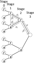
As introduced by E. Arikan [1], we can construct polar code by successively performing channel polarization. Fig. 1a shows an example of the construction of 8-bit polar code. Mathematically, polar codes are linear block codes of length . The coded codeword is computed by where , and is the -th Kronecker power of . Each row of is corresponding to an equivalent polarizing channel. For an polar code, bits that carry source information in are called information bits. They are transmitted via the most reliable channels. While the rest bits, called frozen bits, are set to zeros and are placed at the least reliable channels.
Polar codes can be decoded by recursively applying successive cancellation to estimate from the channel output and the previously estimated bits . This method is referred as successive cancellation (SC) decoding. Actually, SC decoding can be regarded as a binary tree traversal as described in Fig. 1b. The number of bits of one node in stage is equal to . stands for the soft reliability value, typically is log-likelihood ratio (LLR). Each left and right child nodes can calculate the LLR for current node via and functions, respectively [7]. However, in order to solve function, a feedback from left child of the same parent node is needed. This kind of feedback is called partial sum. At stage 0, of a frozen node is always zero, and for information bit its value is calculated by threshold detection of the soft reliability according to
| (1) |
At intermediate stages, can be recursively calculated by
| (2) |

II-B Constituent codes based SC decoding
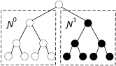
SC decoding generally suffers from the high latency due to its inherent serial property. The processing of obtaining the partial sum from each node significantly constrains the decoding speed. Thus, in order to reduce the latency caused by partial sum calculation, constituent code based SC decoding has been proposed [17], [18]. By finding some certain patterns in the source code, some part of the codeword and their corresponding partial sums can be estimated immediately without traversal. This method significantly reduces the partial-sum-constrained latency. , , and are the four commonest constituent code.
and only contain either frozen bits or information bits, respectively. For codes, we can set the corresponding partial sums to immediately. For node, the partial sums can be directly determined via threshold detection Eq. (1). and contain both frozen bits and information bits. In the codes, only the first bit is frozen. It makes the length constituent codes as a rate single parity check (SPC) code. This kind of code can be decoded by performing parity check with the least reliable bit. Typically it is the one with the minimum absolute value of LLR. In the codes, only the last bit is information bit. In this case, all the corresponding partial sums should be the same since they all are the reflection of the last information bit. Thus, the decoding algorithm starts by summing all input LLRs and the partial sums are calculated by performing the hard detection to the final summary. Fig. 2 shows an example of how constituent code can simplify the SC decoding tree. According to T. Che’s implementation of constituent code based SC decoder [19], the latency of length constituent code can be reduced from to 1, 1, and for , , and codes, respectively. In order to further optimize the performance constituent codes based decoder, a specific designed PSG for it is very necessary.
II-C Shift-register-based partial sums generator
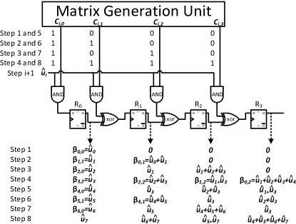
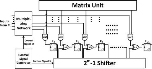
Among all the aforementioned PSGs design, shift-register-based PSG (SR-PSG) has a better performance in terms of both the timing and hardware complexity. For length polar code decoder, it consists of registers and some other simple combination logic. Along with the estimation of each , the registers perform shift calculation and the partial sums can be obtained from their corresponding register. Its architecture is illustrated in Fig. 3. This architecture is built according to the following rule:
| (3) |
where and stand for and - operation, respectively. In Fig. 3, means the th register, means the th estimated bit. means the th partial sum in stage . means the th row and th column in the generate matrix . The matrix generation unit is able to generate with very simple logic. The SC decoder consists of many basic computation parts called processing unit (PU). Each partial sum needs to be feed into the corresponding PU. The shift register based architecture can guarantee that all partial sum required by a PU are all generated in the same register, which can avoid any extra routing logic in the circuit.
Such architecture is able to receive the estimated bit and update the corresponding partial sum by every valid cycle, which is highly consistent with SC decoding processing. However, this architecture is not suitable for constituent codes based SC decoder since some partial sums are obtained directly instead of calculating from estimated bits. Thus, a PSG for constituent codes based SC decoder should have the capability to generate the new partial sums from either the directly got intermediate partial sums or the estimated bits, and to maintain the coherence of them.
III Proposed Design
In this section, we first derive the mathematical presentation of constituent code based partial sum from Eq. (3). Then, the overall hardware architecture and subsequent design details are presented.
III-A Mathematical Presentation


For a length constituent code, its corresponding estimated bits and partial sums are denoted as and , respectively. All the are obtained at the same time. For those bits that do not belong to any constituent codes, we still have to calculate their corresponding partial sums accroding to Eq. (3). Thus, if we still want to keep consistency between directly calculated intermediate partial sums and the one-by-one-estimated bits, we need to derive the mathematical presentation with from Eq. (3).
For and , according to Eq. (3), we have
| (4) | ||||
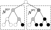
As we know, is the element of generation matrix which is the Kronecker power of . Combine this property with our observation on the matrix, we conduct the following rule which is also noted in Fig. 4a.
| (5) |
According to the definition of generation matrix and concept of constituent code, when , the right part of Eq. (5) is equal to a all vector, and when the right part of Eq. (5) is equal to the th column in the generation matrix for length polar code. According to the definition of partial sum and Eq. (2), we get
| (6) |
where .
Now we apply the above observation back to Eq (4). We define the vector and for . We also define the vectors and . Then, we have
| (7) | ||||
For the consistent with Eq. (3), we rewrite Eq. (7) as follow:
| (8) |
where stands for the bit-wise operation.
For , similar to Eq. (4), we have
| (9) |
According to the definition of and constituent codes, we can conduct that for any length constituent codes, the first columns of its corresponding rows in should also be a generation matrix for length polar code. As described in Fig. 4b, the diagonal cycle shift is same as each correspond column, and consider the is a lower triangular matrix, we get
| (10) | ||||
Thus, Eq. (9) can be rewritten as:
| (11) | ||||
Thus, combining Eq. (11) and Eq. (8), we derive the mathematical presentation for partial sum of constituent based polar decoder as follow:
| (12) |
III-B Proposed architecture
According to Eq (12), the shift-register constituent-code based partial sum generator (SR-CB-PSG) is proposed as in Fig. 5. Compared with Fig. 3, there are three differences. The first difference is the input. For SR-PSG, only current estimated bit is sent into, which means the input is only from the from stage . However, for SR-CB-PSG, the inputs are from s of any stage, depending on the length of constituent code. Thus, a multiplexing networking is needed to route all the inputs values to the right registers. The second difference is the shift function. According to Eq (12), instead of just shifting by one bit, the shifter should have the capability to shift -bit where is the length of constituent code. According to the definition of constituent code, should be the any power of . Thus, A specific design -bit shifter is proposed. The control signals for both the muxing networking and shifter are from the with simple logic. The last difference is matrix generation unit. For each constituent code, its corresponding should be the th row of the generation matrix, where is the index of the last bit in the constituent code. Due to the irregularity of the constituent code, it’s unnecessary to build an online generator for that. Thus, a pre-calculated ROM is placed. It is a trade-off between design complexity and hardware resource. It can be replaced by a re-configurable memory device like RAM for flexibility.
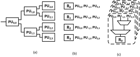
Fig. 6 shows an example of partial sum routing for 8 bit constituent code based polar code. We can see each register has specific corresponding PU from each stage. They need the multiplexing networking to route the partial sums to the each right register. For length polar code, there are stages in the decoder and registers in the SR-CB-PSG. If the multiplexing networking is built from the basic 2-bit MUX, each register is assigned an identical MUXs networking made by MUXs. All the networkings share the same control signal. According to its architecture, the control signals are the direct binary mapping of its stage index. In total, MUXs are needed. Since the multiplexer networking needs to wait each PU finish computing to get the valid inputs, it is on the critical path of the decoder. Thus, it causes additional delay, where is the delay for a single MUX.
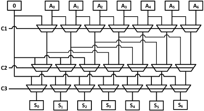
For the shifter, we proposed a barrel-shifter-based architecture. For length polar code, . The shifter performs logic right shift. For , where is the index of the register and is the length of the current constituent code, zeros are added to the left. For , we do shift. Those behaviors satisfy the first and second in Eq (12).
Fig. 7 shows an example of shifter for 16-bit polar code decoder. All the MUXs in the same row can shall the same control signal. Those signals are generated by a , where for length polar code. For length polar code, there are MUXs are needed for the shifter. Since the shifter can start shift data without waiting to finish computing, it is not on the critical path. Thus, it should not deteriorate the timing performance of the decoder at all.
IV Implementation results and discussions
To the best of our knowledge, the proposed design is the first PSG design especially design for constituent codes based SC decoder. Thus, there is no reference design we can directly compare with. In this section, we list all the results we have and presents some relevant discussions.
| Critical Path | |
| SR-PSG[14] | |
| Proposed |
Table I shows the critical path comparison between proposed PSG and the PSG in [14]. We can tell the delay overhead comes from the muxing network. Ideally, the maximum frequency of constituent codes based SC decoder is lower than that of conventional SC decoder. However, after taking the latency reduction into account, as shown in Table II, constituent codes based SC decoder is able to achieve much higher throughput. The conventional SC decoder is referred from [9] which is the lowest latency conventional SC decoder to the best of out knowledge.
| code rate | |||||
| 0.2 | 0.35 | 0.5 | 0.65 | 0.8 | |
| latency of conventional [9] | 767 | ||||
| latency of constituent code based | 263 | 298 | 266 | 200 | 160 |
| reduction() | 65.7 | 61.1 | 65.3 | 73.9 | 79.1 |
Table III shows the resource consumption estimation of proposed SR-CB-PSG for length polar code decoder and the comparison with other two conventional PSG. The most resource consumption part is the since it used in both multiplexer networking and shifter. The estimation for the ROM size is based on the average calculation since the decoding latency changes along with the code rate.
The proposed design can be targeted on either ASIC or FPGA. We synthesized both with Nangate FreePDK 45nm process and on Xilinx Kintex-7 FPGA KC705 Evaluation board. Table IV shows the hardware resource of SR-CB-PSG for 1024 code length polar code decoder on both of them.
| XC7K325T-2FFG900C FPGA | nangate 45nm | ||
| Hardware Resource | slice LUTs | slice REGs | area |
Noticeably, the architecture we discussed in this paper is based on the consideration for the worst case, which is that the maximum length of constituent codes could be . However, for practical application, the maximum length of constituent is fix for certain code rate and usually cannot approach . For those case, the logic of both the multiplexer networking and shifter could be even simpler, which will result in a better timing and silicon area performance.
V Conclusion
This paper proposed an efficient PSG hardware design for constituent code based SC decoder. Conventional PSG is not compatible with the constituent code based SC decoder. This is because that the conventional one is only capable of taking estimated bit one by one but the constituent code based decoder is generated the intermediate partial sum directly. To solve this problem, we first derive the mathematical presentation for constituent code based PSG from the SR-PSG for conventional SC decoder. Then, the overall hardware architecture and design details are proposed. Finally, the implementation result with both VLSI and FPGA technology are presented, and the relevant discussions are carried out.
References
- [1] E. Arikan, “Channel polarization: A method for constructing capacity-achieving codes for symmetric binary-input memoryless channels,” Information Theory, IEEE Transactions on, vol. 55, no. 7, pp. 3051–3073, 2009.
- [2] I. Tal and A. Vardy, “List decoding of polar codes,” in Information Theory Proceedings (ISIT), 2011 IEEE International Symposium on. IEEE, 2011, pp. 1–5.
- [3] N. Hussami, S. B. Korada, and R. Urbanke, “Performance of polar codes for channel and source coding,” in Information Theory, 2009. ISIT 2009. IEEE International Symposium on. IEEE, 2009, pp. 1488–1492.
- [4] J. Xu, T. Che, and G. Choi, “Xj-bp: Express journey belief propagation decoding for polar codes,” in 2015 IEEE Global Communications Conference (GLOBECOM). IEEE, 2015, pp. 1–6.
- [5] B. Yuan and K. K. Parhi, “Architecture optimizations for bp polar decoders,” in Acoustics, Speech and Signal Processing (ICASSP), 2013 IEEE International Conference on. IEEE, 2013, pp. 2654–2658.
- [6] J. Lin, J. Sha, L. Li, C. Xiong, Z. Yan, and Z. Wang, “A high throughput belief propagation decoder architecture for polar codes,” in Circuits and Systems (ISCAS), 2016 IEEE International Symposium on. IEEE, 2016, pp. 153–156.
- [7] C. Leroux, A. J. Raymond, G. Sarkis, and W. J. Gross, “A semi-parallel successive-cancellation decoder for polar codes,” Signal Processing, IEEE Transactions on, vol. 61, no. 2, pp. 289–299, 2013.
- [8] C. Zhang and K. Parhi, “Low-latency sequential and overlapped architectures for successive cancellation polar decoder,” Signal Processing, IEEE Transactions on, vol. 61, no. 10, pp. 2429–2441, 2013.
- [9] B. Yuan and K. K. Parhi, “Low-latency successive-cancellation polar decoder architectures using 2-bit decoding,” IEEE Transactions on Circuits and Systems I: Regular Papers, vol. 61, no. 4, pp. 1241–1254, April 2014.
- [10] T. Che, J. Xu, and G. Choi, “Overlapped list successive cancellation approach for hardware efficient polar code decoder,” arXiv preprint arXiv:1511.00577, 2015.
- [11] A. Balatsoukas-Stimming, A. J. Raymond, W. J. Gross, and A. Burg, “Hardware architecture for list successive cancellation decoding of polar codes,” Circuits and Systems II: Express Briefs, IEEE Transactions on, vol. 61, no. 8, pp. 609–613, 2014.
- [12] A. Balatsoukas-Stimming, M. Bastani Parizi, and A. Burg, “Llr-based successive cancellation list decoding of polar codes,” in Acoustics, Speech and Signal Processing (ICASSP), 2014 IEEE International Conference on. Ieee, 2014, pp. 3903–3907.
- [13] J. Lin and Z. Yan, “A hybrid partial sum computation unit architecture for list decoders of polar codes,” in 2015 IEEE International Conference on Acoustics, Speech and Signal Processing (ICASSP). IEEE, 2015, pp. 1076–1080.
- [14] G. Berhault, C. Leroux, C. Jego, and D. Dallet, “Partial sums generation architecture for successive cancellation decoding of polar codes,” in SiPS 2013 Proceedings. IEEE, 2013, pp. 407–412.
- [15] ——, “Partial sums computation in polar codes decoding,” in 2015 IEEE International Symposium on Circuits and Systems (ISCAS). IEEE, 2015, pp. 826–829.
- [16] Y. Fan and C.-y. Tsui, “An efficient partial-sum network architecture for semi-parallel polar codes decoder implementation,” IEEE Transactions on Signal Processing, vol. 62, no. 12, pp. 3165–3179, 2014.
- [17] A. Alamdar-Yazdi and F. R. Kschischang, “A simplified successive-cancellation decoder for polar codes,” IEEE communications letters, vol. 15, no. 12, pp. 1378–1380, 2011.
- [18] G. Sarkis, P. Giard, A. Vardy, C. Thibeault, and W. J. Gross, “Fast polar decoders: Algorithm and implementation,” Selected Areas in Communications, IEEE Journal on, vol. 32, no. 5, pp. 946–957, 2014.
- [19] T. Che, J. Xu, and G. Choi, “Tc: Throughput centric successive cancellation decoder hardware implementation for polar codes,” in 2016 IEEE International Conference on Acoustics, Speech and Signal Processing (ICASSP). IEEE, 2016, pp. 991–995.