Leaky Wires: Information Leakage and Covert Communication Between FPGA Long Wires
Abstract.
Field-Programmable Gate Arrays (FPGAs) are integrated circuits that implement reconfigurable hardware. They are used in modern systems, creating specialized, highly-optimized integrated circuits without the need to design and manufacture dedicated chips. As the capacity of FPGAs grows, it is increasingly common for designers to incorporate implementations of algorithms and protocols from a range of third-party sources. The monolithic nature of FPGAs means that all on-chip circuits, including third party black-box designs, must share common on-chip infrastructure, such as routing resources. In this paper, we observe that a “long” routing wire carrying a logical 1 reduces the propagation delay of other adjacent but unconnected long wires in the FPGA interconnect, thereby leaking information about its state. We exploit this effect and propose a communication channel that can be used for both covert transmissions between circuits, and for exfiltration of secrets from the chip. We show that the effect is measurable for both static and dynamic signals, and that it can be detected using very small on-board circuits. In our prototype, we are able to correctly infer the logical state of an adjacent long wire over 99% of the time, even without error correction, and for signals that are maintained for as little as 82us. Using a Manchester encoding scheme, our channel bandwidth is as high as 6kbps. We characterize the channel in detail and show that it is measurable even when multiple competing circuits are present and can be replicated on different generations and families of Xilinx devices (Virtex 5, Virtex 6, and Artix 7). Finally, we propose countermeasures that can be deployed by systems and tools designers to reduce the impact of this information leakage.
See title-page.pdf
1. Introduction
The ever-increasing size and sophistication of FPGAs make them an ideal platform for System-on-Chip integration. FPGAs are often used in high-bandwidth, low-latency applications, providing functionality such as network card replacement, or massively parallel computation. Besides permeating distributed systems and critical infrastructure, FPGA chips are also integrated in end-products, ranging from consumer electronics to medical and scientific equipment. As a result, protecting their security is a necessary step to ensure that their computations are performed in a trustworthy manner.
The high cost of design and development has led to an increase in outsourcing, making it common to have designs from different contractors on the same FPGA chip. Such designs often include protocol and data structure implementations, or more sophisticated circuits, like radio front-ends or soft processors. This practice raises concerns about the malicious inclusion of circuits (cores) that have additional backdoor functionality. The cores can be functionally validated before being included in the overall design, but such static analysis cannot always detect covert channels (Huffmire et al., 2008). It is therefore important to identify and protect against such channels.
In this paper, we show that the value driven onto certain types of FPGA routing resources, called “long” wires, influences the delay of nearby wires, even when the driven value remains constant. This distinguishes our approach from prior work which depends on fast-changing signals (Gag et al., 2012; Kelly et al., 2015; Zhang and Tehranipoor, 2011), and thus local voltage drops or inductive crosstalk. Specifically, we find that if a long wire carries a logical 1, the delay of nearby long lines will be slightly lower than when it carries a logical 0. This difference in delay allows cores sharing the same reconfigurable FPGA fabric to communicate, even when they are not directly connected.
We demonstrate the phenomenon by building a transmitter and receiver, which are unconnected, and only use adjacent long wires to communicate. The receiver is a three-stage Ring Oscillator (RO), whose routing uses a long wire between two of its stages. The transmitter drives a long wire adjacent to that of the RO. When the transmitting wire carries a logical 1, the routing delay of the RO long wire decreases, thereby increasing the RO frequency. We detect these minor frequency changes by counting the number of the RO signal transitions during a fixed time interval. This mechanism can be used either for covert communication, or for the exfiltration of fast-changing dynamic signals.
We conduct extensive experiments on three Xilinx FPGA families and show that the phenomenon is independent of the device used, the location and orientation of the transmitter and receiver, and the pattern of transmission. We perform all tests on stock prototyping boards without modifications, and show that the phenomenon can be detected even in the presence of environmental noise and with only small circuits internal to the FPGA. Finally, we propose new defense mechanisms which can be implemented by systems and tools designers to reduce the impact of this information leakage.
2. Background
Field-Programmable Gate Arrays (FPGAs) are integrated circuits that implement reconfigurable hardware. At a basic level, they consist of blocks of configurable lookup tables (LUTs), which can be used to represent the truth table of combinatorial functions. They also include registers to store data, as well as programmable routing, which determines how the LUTs and registers are interconnected. FPGAs can thus be used to represent all computable functions, including emulating sophisticated circuits such as entire CPUs.
The Xilinx FPGAs used in our experiments internally have a grid layout, whose fundamental building block is called a Configurable Logic Block (CLB). It is composed of two slices, each of which contains four LUTs and registers. Each CLB has an associated switch matrix, which contains resources to connect elements within a CLB, and enables CLBs to communicate with each other. There are multiple types of such communication wires, which have different orientations and lengths. In this paper we focus on a specific type of routing resource, called a long. Longs are a wire type used to efficiently communicate between CLBs that are far apart, and can be vertical (connecting elements with the same coordinate), or horizontal (same coordinate). We have observed the phenomenon in both types of wires, but for brevity we limit our discussion to vertical longs, or VLONGs. Due to the FPGA’s routing topology, additional shorter wires are often needed to connect certain elements via long wires. We will refer to these wires as “local routing”.
Usually, the details of how logic elements are placed and signals are routed are transparent to the circuit designers. Designers define their desired logic, but the conversion to a physical implementation is handled by the manufacturer tools. Compiler directives for the manual routing of signals are available, but these are often only used if the exact routing impacts functionality. In the absence of manual directives, the tools may elect to use any wire, including longs, to carry a given signal in the circuit, without alerting designers.
That said, user-designed circuits often share the FPGA with third-party implementations of various protocols, data structures, and algorithms. These licensed designs, called Intellectual Property (IP) cores or blocks, often come in a pre-routed black-box format, to eliminate the variability of on-the-fly routing and attain a known clock frequency. As a result, the routing of these blocks is opaque to circuit designers, and blocks created by different parties can use routing resources in the same channel of long wires. As our paper shows, this use of nearby long wires can enable malicious circuits to communicate covertly, or extract information from other cores.
Ring Oscillators (ROs) are a type of circuit which consists of an odd number of NOT gates, chained together in a ring formation (i.e., the output of the last gate is fed back as input to the first gate). ROs form a bi-stable loop, whose output oscillates between 1 and 0 (true and false). The frequency of oscillation depends on the number of stages in the RO, the delay between the stages, as well as voltage, temperature, and small variations in the manufacturing process (Hajimiri et al., 1999). ROs in FPGAs are used as temperature monitors (Zick and Hayes, 2012), True Random Number Generators (TRNGs) (Vasyltsov et al., 2008), and Physically-Unclonable Functions (PUFs)s (Maiti et al., 2010), while in this paper we present a way to use them to detect the logic state of nearby wires.
3. System and Adversary Model
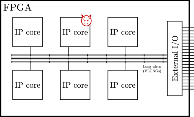
FPGA designs contain IP cores sourced from third-parties, and some of these cores may contain unwanted functionality, as shown in Figure 1. These third-party IP cores can be distributed as fully-specified, pre-placed and pre-routed elements (“macros”) to meet timing constraints (e.g., DDR controllers) and reduce compilation time, with the macro repositioned at specific intervals where the logic and routing fabric is self-similar (Korf et al., 2011; Lavin et al., 2013; Lavin et al., 2010, 2011).
As FPGAs often process highly-sensitive information (e.g., cryptographic keys), it is essential to ensure that data does not leak to unauthorized third-parties. In this paper, we focus on malicious IP cores which aim to infer information about the state of nearby (but physically-unconnected) logic. The adversary can thus insert one or more IP cores into the design, but these cores are not directly connected. The adversary can also define the internal placement and routing of his own blocks and force his cores to use specific routing resources that can compromise the integrity of a reverse-engineered target IP block. Note that directly connecting to the target IP block would result in a logical error in the compilation flow, but merely using adjacent wires does not raise such errors. We discuss how the adversary can accomplish his goals in Section 3.2.
The adversary does not have physical access to the board, and can thus not alter the environmental conditions or physically modify the FPGA board in any way. There is also no temperature control beyond the standard heatsink and fan already mounted on the FPGA, and we do not add any special voltage regulation, or shielding to the chip or the connected wires. Such modifications reduce noise and improve the stability of measurements (Lecomte et al., 2015; Moradi, 2014; Sun et al., 2011; Zick and Hayes, 2012), and would thus make it easier for the adversary to achieve his goals.
In this paper, we show that by using long wires, an adversary can infer the nearby state of blocks he does not control, or establish covert communication between two co-operating IP cores under his control, even in the presence of power and temperature fluctuations. We provide further motivation and applications of the capabilities offered by this new source of information leakage in Section 3.1.
3.1. Motivation
With increased outsourcing, Hardware Trojans (HTs) have become a common-place security threat for FPGAs (Chakraborty et al., 2013; Tehranipoor and Koushanfar, 2010). Adversarial IP cores can thus eavesdrop on nearby cores and attempt to extract information about their state. As designs are often tested to detect HTs and other security threats (Kelly et al., 2015; Lecomte et al., 2015; Zhang and Tehranipoor, 2011), we thus assume that the IP cores provide legitimate functionality that is needed by the user, and that they do not contain additional logic which would make them easy to detect. Indeed, the transmitter and receiver we present have dual use, hiding their malicious functionality in their routing, not their actual combinatorial and sequential logic. As a result, unlike conventional backdoors, our IP cores would pass timing/netlist/bitfile verification, since they do not require additional gates, presenting a bigger challenge to designers.
Multi-user setups present further threats beyond a malicious core eavesdropping on signals not under the adversary’s control. Intel Xeon and other CPUs with integrated FPGAs bring FPGAs closer to a traditional server model, while FPGAs in cloud environments (e.g., Amazon EC2 F1 instances) are also becoming increasingly available. Although these are currently allocated on a per-user basis, we can expect that they will eventually become sharable commodity resources, since FPGAs already allow for partial reconfiguration, and designs exist where different processors have access to and can re-configure the same FPGA chip (Smith and Ventrone, 2011).
An additional threat arises when IP cores of different security guarantees are integrated on the same design (Huffmire et al., 2008; Iakymchuk et al., 2011; Shila et al., 2015). For example, an adversary implementing the FM radio core on a phone SoC would want to eavesdrop on the Trusted Platform Module’s (TPM) AES encryption operations to recover its key. As sensitive cores are highly scrutinized, an adversary who has also implemented the TPM would want to establish a covert channel to transfer the key using an inconspicuous transmitter.
3.2. Influencing Placement and Routing
A potential issue with pre-placed and pre-routed IP cores is that they are specific to an FPGA generation (but can be used in different devices within the same family). As we show in Section 7.2, however, the phenomenon we present persists across 3 generations of Xilinx chips. As a result, an adversary can provide an IP generation wizard that provides different routing for different families, and dynamically choose the placement of the IP cores. In fact, as we show in Section 8, the location of the actual logic and wires is not important, so the adversary merely needs to ensure that the transmitter and the receiver use long wires which are adjacent.
If the adversary only pre-routes but does not pre-place his cores, he can still succeed, even if he leaves the absolute placement of his cores to the routing tools. Assume the FPGA has long wires, the transmitted signal can be recovered from nearby wires, the receiver uses longs, and the transmitter uses longs. Then, the probability that at least one segment of the transmitter is adjacent to a segment of the receiver is , assuming the tools place the two cores at random. For the FPGA boards we have used, (equal to the number of CLBs) and , so with , an adversary has a 0.42% chance of success. Since tools do not pick locations at random or spread the logic, the probability of success is higher in practice. The adversary can also increase this probability by accessing relatively unique elements such as Block RAM (BRAM), DSP blocks, or embedded processors on the FPGA fabric. For example, the devices we used have less than 150 DSP slices and 300 BRAM blocks, so accessing them reduces the number of possible placements for the attacker’s cores.
A more powerful adversary can instead subvert the compilation tools themselves, which is a common threat model for FPGAs (Huffmire et al., 2008; Krieg et al., 2016). Note that, as before, since the final netlist itself is often verified post-synthesis and -routing, the adversary still does not desire to include additional logic in the design, but just affect the routing/placement of his malicious cores. Finally, in co-located multi-user instances, the adversary is the user, so he can always choose the location of his own cores, without the need to rely on the above.
4. Channel Overview
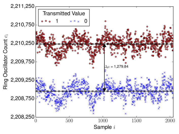
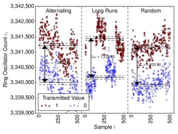
Our channel exploits the fact that the delay of long wires depends on the logical state of nearby wires, even when the signals they are carrying are static. We find that when the transmitting wire carries a 1, the delay of the nearby receiving wire is lower, which results in a higher number of ring oscillator (RO) counts. This is a distinct mechanism from prior research, which depends on the switching activity of nearby circuits, which decreases RO frequency (Kelly et al., 2015; Zhang and Tehranipoor, 2011), as we also independently verify in Section 6.3.
This dependence on the logical state of the transmitter is shown in Figure 2. The red dots and blue x’s are RO counts when the transmitter wire carries a logical 1 or 0 respectively. The difference between the counts when transmitting 1s and 0s is clear, even under local fluctuations due to environmental and other conditions: even when the absolute frequencies of the ring oscillator change, the difference between the two frequencies remains the same.
In order to characterize the efficacy and quality of the communication channel in detail, we perform a number of experiments, the setup of which is detailed in Section 5. We first show in Section 6 that the strength of the effect does not depend on the transmission pattern, by measuring the effect of an alternating sequence of 0s and 1s, as well as that of long runs of 0s and 1s, and of pseudo-random bits. We illustrate that even for fast-changing dynamic signals, an eavesdropping attacker can obtain the fraction of 1s and 0s, i.e., the Hamming weight on the transmitting wire.
We then show that longer measurement periods and overlaps make it easier to distinguish between different bits in Section 7. The strength of the effect changes based on the receiver and transmitter lengths, and this dependence exists across generations of devices, but with a different magnitude. We also demonstrate that the absolute location and orientation of the transmitter and receiver do not change the magnitude of the effect in Section 8.
Finally, we show in Section 9 that the channel remains strong, even if significant computation is happening elsewhere on the device simultaneously, showing that the channel can be used in a realistic environment. We demonstrate that for the transmitted information to be detectable, the transmitter and receiver wires need to be adjacent, but where exactly and in what direction the overlap occurs is not significant. This indicates that it may be difficult for designers to protect themselves from eavesdropping, or detect intentional malicious transmissions.
Overall, we show that the channel is stable across FPGA generations, devices, and locations within a device. It is also high-bandwidth, and can be used to implement both covert communications and eavesdropping attacks, without tapping into existing signals, and with minimal resources, as we explain in Section 10.
5. Experimental Setup
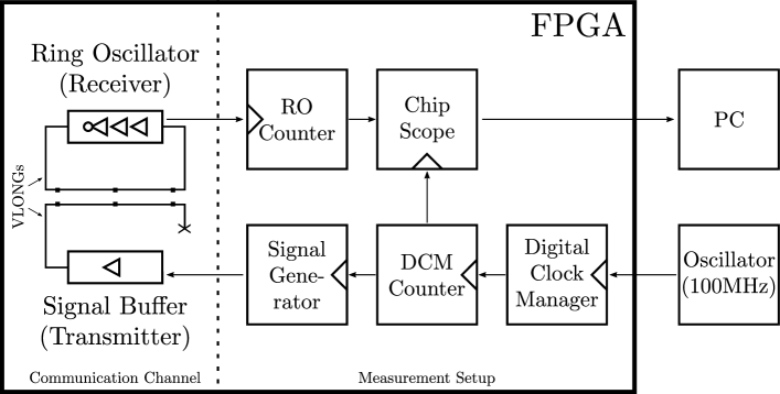
In order to test the properties identified in Section 4, we need to determine the factors we wish to vary, keeping the rest of the setup fixed. This distinction naturally divides our experimental setup into two parts, as shown in Figure 3. The communication channel circuit contains just the transmitter and the Ring Oscillator receiver. The measurement half works independently of any specific channel implementation, generating the transmitted signal, sampling the RO counter, and transferring the data to a PC for analysis.
The bulk of our experiments are conducted on three Virtex 5 XUPV5-LX110T (ML509) evaluations boards. The boards include a heatsink and a fan, but we do not otherwise control for temperature, and we also do not modify the board in any way (e.g., by bypassing the voltage regulator) in accordance with our threat model. Each experiment is run on every device 5 times, collecting 2048 data points per run, and results are reported at the 99% confidence level.
5.1. Transmitter and Receiver
To illustrate the information leakage, our setup employs a minimal transmitting circuit: the transmitter consists of a buffer LUT that drives one or more long-wire segments connected end-to-end. We use the term transmitter for brevity and because in the controlled experiments we choose the value on the long wire, but the conclusions we draw are valid whether transmissions are intentional or not. The receiving circuit also uses long wires that are adjacent to the transmitter’s wire segments. To measure the delay of the receiver’s long wire segment(s), we include it as part of a three-stage ring oscillator. As in (Sun et al., 2011), the oscillator contains one inverter (NOT gate) and two buffer stages. The wire’s delay directly influences the frequency of oscillation, which we estimate by feeding the output of one of the RO stages to a counter in our measurement setup.
5.2. Measurement Setup
The measurement component generates the signals to be transmitted and measures the RO frequency. A new trigger event is produced every clock ticks. At every trigger, the RO counter is read and reset, and a new value is presented to the transmitter. For most experiments, the signal generator simply alternates between 0s and 1s, but we change the pattern in Section 6 to show the generality of the channel.
The 100MHz system clock is driven by a Digital Clock Manager (DCM) to ensure clock quality. For the majority of our experiments, we fix (corresponding to clock ticks, or ), but vary in Section 7.1 to explore the accuracy vs. time trade-offs. The sampled data is transferred to a PC for analysis through Xilinx’s ChipScope Integrated Logic Analyzer (ILA) core.
Unlike the circuit described above, the measurement logic is not hand-placed or hand-routed, due to the large number of experiments performed. Although the measurement logic could influence the RO frequency (Merli et al., 2010), we repeat our experiments on multiple locations, control for other patterns, and average over relatively lengthy periods of time. Thus, we believe that any effects of the measurement circuitry would influence the transmission of both zeros and ones equally, a hypothesis we confirm in Section 9 by observing that the channel is only affected by adjacent wires.
5.3. Relative Count Difference
When a clock of frequency is sampled every ticks and a ring oscillator of frequency driving a counter measures ticks, then , with an appropriate quantization error due to the unsynchronized nature of the RO and the system clock. Thus,
| (1) |
where and represent the count and respective frequency when the transmitter has value . As a result, the relative change of frequency can be approximated just by the measured counts, irrespective of the measurement and clock periods.
In the basic setup, the transmitter alternates between sending zeros and ones. We denote the -th sampled count as , so the pair always corresponds to different transmitted values. For the sake of notation clarity, we will assume that corresponds to a transmitted and we will be using the quantity
to indicate the relative frequency change between a transmitted one and zero. will denote the average of over all measurement pairs . We discuss different transmission patterns in Section 6 and how to exploit the measurements in Section 10.
6. Transmitter Patterns
In this section we show that the phenomenon observed does not fundamentally depend upon the pattern of transmissions, i.e., that only the values carried by the wire during the period of measurement matter, and not the values that precede or follow it. We first show this for relatively constant signals (Section 6.1), and then for highly dynamic ones (Section 6.2). Finally, we compare our results to those produced by switching activity, which is traditionally discussed in the context of Hardware Trojan detection (Section 6.3).
6.1. Constant Signals
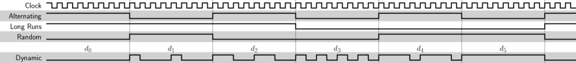
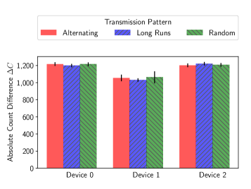
In the default setup, we use a slowly alternating signal, where the transmitted value changes every sampling period. This pattern is denoted by in Figure 4. In this experiment, the transmitted value still remains constant within a given measurement period, and we sample the ring oscillator at the same default rate (every ), but change how the signal generator chooses the next value to be transmitted. The first additional pattern we test greatly slows down the alternation speed of the transmitted signal. This pattern maintains the same value for 128 consecutive triggers—in essence, testing the effects of long sequences of zeros and ones. The second setup employs a Linear Feedback Shift Register, which produces a pseudo-random pattern of zeros and ones, and is denoted by in Figure 4.
The results of this test are shown in Figure 5, with a sample of the data in Figure 5(a), and a comparison across devices in Figure 5(b). The RO counts remain significantly higher when transmitting a 1 versus a 0, and the average count difference remains identical, with almost no variability among the patterns. We deduce that the pattern of transmission has no persistent effect on the delay of nearby wires, allowing the channel to be used without having to ensure a balanced distribution of transmitted values.
6.2. Dynamic Patterns
To show that the dominating factor in the observed phenomenon is the duration for which the transmitter remains at a logical 1, and not the switching activity of the circuit, we try various dynamic patterns. As a result, even if a signal is not sufficiently long-lived, the attacker can still deduce the signal’s Hamming Weight (HW), and thus eavesdrop on signals he does not control. We explain in Section 10.2 how to use this property to recover cryptographic keys through repeated measurements.
The dynamic patterns used are denoted by in the timing diagram of Figure 4. During each sampling period, we loop the transmitter quickly through a 4-bit pattern at 100MHz. We test six different 4-bit patterns, only updating the looped pattern at each new sampling period. For example, for the pattern 1100 ( in Figure 4), the transmitter would stay high for two 100 MHz clock ticks, then low for two clock ticks, then back to high for 2 ticks, etc., until the end of the sampling period. The six 4-bit patterns used are: , , , , , and . These patterns respectively have a HW of , , , , , and %, while their switching frequencies are , , , , , and respectively.
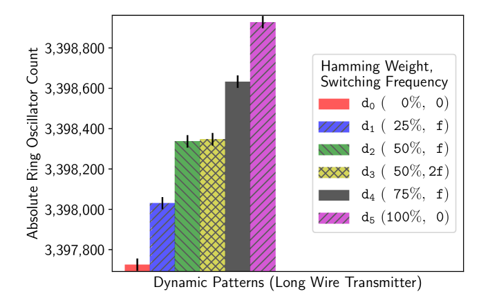
Figure 6 shows the average count of the ring oscillator for each of pattern . We see that the RO frequency increases with the Hamming Weight, so that . However, the frequency is otherwise unaffected by the switching transmission activity: the Kolmogorov-Smirnov test suggests that there is no statistically significant difference between the two distributions for and . Note that the receiver would not able to distinguish between patterns and as a result (or more generally, any patterns with the same Hamming Weight), but we explain how to overcome this limitation in Section 10.2.
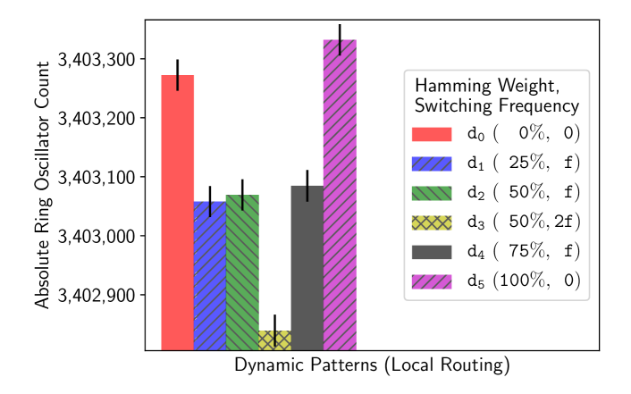
6.3. Local Routing
In this section, we show that when the two circuits do not have overlapping long wires, switching activity decreases the oscillation frequency of the RO. This reproduces the results reported by prior research on Hardware Trojan detection (Kelly et al., 2015; Zhang and Tehranipoor, 2011) and also allows us to sanity-check our measurement setup. To test this dependence on the long wire overlap, we remove the transmitter using long wires, and replace it with a buffer of consecutive LUTs packed into CLBs, using only local intra- and inter-CLB routing. We then drive the same 6 dynamic patterns from Section 6.2 through the buffer, and measure the results in Figure 7. We can clearly see that the ordering of the patterns exactly mirrors their relative switching activity, with the RO counts corresponding to decreasing with increased switching activity: . The difference between the patterns with the same switching activity , , is not significant according to the Kolmogorov-Smirnov test, but the count is slightly higher for compared to , which have no switching activity. This suggests that the phenomenon we have identified and which reduces delay may be present for shorter wires as well, but is considerably weaker, and requires much bigger circuits. Overall, we can conclude that when the transmitter does not use longs which overlap with the receiver and generates a lot of switching activity through multiple redundant buffers, then the observed RO frequency is indeed reduced, reproducing the results of prior work.
7. Measurement Parameters
In this section, we discuss the trade-offs between the quality of the channel and the measurement time (Section 7.1), and length of overlap between receiver and transmitter (Section 7.2).
7.1. Measurement Time
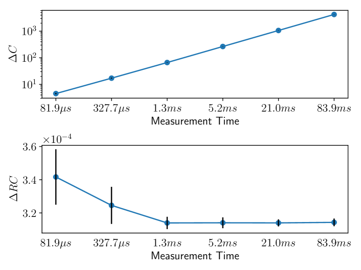
In this experiment, we return to the alternating pattern shown in Figure 4, and vary the measurement time by repeatedly quadrupling it. Both the absolute and the relative count difference for the various times are shown in Figure 8. In the top of the figure, we see that the absolute count difference grows linearly with increasing measurement time. Hence, the RO count differences can be amplified, proportionally to the duration of the measurement.
The relative differences (shown in the bottom of Figure 8) remain approximately constant for measurement periods above , in accordance with our theoretical prediction of Equation (1). The values for shorter measurement periods are still close, but are far noisier: for short measurement periods, the absolute difference is small ( for ), increasing quantization errors, and making it harder to distinguish between signal and noise. These results indicate that for a given receiver/transmitter placement, the absolute magnitude of the effect depends solely on measurement time, with longer measurement periods making it easier to distinguish between signals and noise. An adversary can thus choose the measurement time, trading throughput for lower bit error rate.
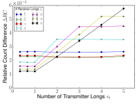
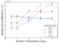
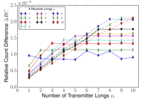
7.2. Wire Length
We also characterize the effect of varying the length (number) of transmitter and receiver wires and in three generations of devices. Besides the Virtex 5 device we have been using so far, we also measure the effect on a Virtex 6 ML605 and on an Artix 7 Nexys 4. The relative change in frequency is shown for different combinations of and in Figure 9, for one device per generation. We notice the same common pattern for all 3 generations of devices.
For a given number of long wires used by the ring oscillator, there are 3 distinct segments for as the number of transmitter longs increases. The first segment occurs for transmitters which use only parts of a long. Using partial wires is possible because even though VLONGs can only be driven from the top or the bottom, they have additional intermediate “taps” which can be used to read the values of the signal they carry. In practice, using partial wires does not have an effect on the strength of the phenomenon: remains constant for all fractions of a long. This result is to be expected since, electrically, the entire long wire is driven even if the output tap does not take full advantage of its length.
The second segment is the region where . Here, increases linearly with , suggesting that the phenomenon affects the delay of each long wire equally. The final region consists of , where remains constant. The reason for this pattern is that there is no additional overlap between the newly added segments of the transmitter and the receiver.
We also identify the effect of a given number of transmitter wires on receivers using a different number of longs . Among receivers with , a smaller results in a larger effect. As an example, for , the effect for is smaller than it is for . This behavior is due to the transmitter affecting only the first out of long wire segments of the ring oscillator. For smaller ring oscillators, these segments represent a larger portion of the number of wires used, and hence of overall delay.
The opposite is true when : the larger the RO, the bigger the resulting effect. For instance, for , the effect for is larger than the effect for . This difference exists because even though the delay of the routing scales linearly, the delay associated with the inverter and buffer LUT stages remains constant. Thus, the routing delay represents a larger fraction of the overall delay (routing delay plus stage delay) for larger ROs. Since this phenomenon only acts on routing delay, larger ROs are affected more than shorter ones.
8. Location Independence
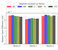
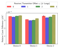
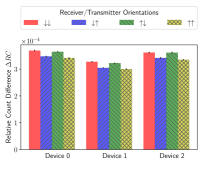
In order to validate the location independence of the channel, we test three different aspects of the placement of the receiver and transmitter on: the absolute location on the device, the relative offset of the receiver and transmitter, as well as the direction of signal propagation. Figure 10 shows the results for all three experiments on the Virtex 5 devices, with 99% confidence intervals. At a high level, the effect remains approximately constant for each device regardless of the choice of parameters. Across devices, the absolute magnitude of the effect varies slightly, but is otherwise almost the same. Any variability across devices is to be expected, since manufacturing variations are known to affect ring oscillator frequencies (Hajimiri et al., 1999).
Figure 10(a) shows the results when an identical circuit is placed on different locations of the device: the four corners (bottom/top left/right) and the center. Both transmitter and receiver use 2 longs each, and they are adjacent: when the receiver’s location is , the transmitter’s location is . Within a device, the values are close, and there is no pattern in how the values change between devices. Manufacturing variations within and between devices can thus explain any variability.
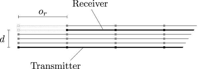
The second experiment investigates the effect of the placement of the receiver and the transmitter relative to each other. When the receiver and transmitter have different lengths, it is possible for the two circuits to have the same overlap, but a different starting offset. This relative offset (visually shown in Figure 11) also has minimal effect on the channel. To test this hypothesis, we place a transmitter made up of 5 longs at a fixed location on the device. The receiver, which uses 2 longs, is placed adjacent to the transmitter, but at an offset of full long wires, allowing for four different offset placements. This offset needs to correspond to full long wire lengths due to constraints imposed by the routing architecture of the device. Any other offset would increase the distance between the transmitter and receiver, which we investigate separately in Section 9. Figure 10(b) presents the results of this experiment, which show approximately the same consistency both within and between devices as those of the previous experiment.
Note that the relative effect of placing the receiver at various offsets forms a consistent pattern across devices. As an example, the effect for an offset is consistently stronger than it is for . This pattern can be explained by the FPGA routing layout: as mentioned in Section 2, the local routing used to get to the various long wire segments is different between each test. Because the local routing resources differ, the ratio between the delay incurred by the long wire segments and the local routing resources changes. As will be discussed in Section 9, while the delay of the long wire segments is affected by the transmitter, the local routing is not.
Using the same setup, and with an offset of full long wires, we change the direction of signal propagation for the transmitter and receiver. In the previous experiments, both signals travelled from the bottom of the device to the top. However, in the Virtex 5 architecture, VLONG wires are bi-directional, and can thus propagate signals upwards or downwards. Figure 10(c) shows the results for the 4 different orientations (receiver and transmitter down, receiver down/transmitter up, etc.). The relative count difference is approximately the same for all configurations, although as with the previous experiment, we notice a consistent ordering for the four transmission directions across devices. Similar to the earlier experiment, this pattern can also be explained by the routing layout.
The results of this section illustrate that only the long wires need to be manually specified, while the registers, LUTs, and local routing can be auto-placed/routed, further reducing the attack complexity.
9. Resilience To Countermeasures
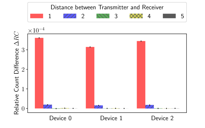
Although we discuss defense mechanisms in more depth in Section 11, in this section we evaluate how close to the transmitter a receiver would have to be in order to decode a message. We do this by varying the distance (depicted in Figure 11) between the transmitter and the receiver. The results are shown in Figure 12. We see that the phenomenon is still measurable when separating the wires by a distance of , but the effect is times weaker. When the wires are farther apart (), there is no correlation between the transmitted and received values, i.e., the data comes from the same distribution according to the Kolmogorov-Smirnov test (). In other words, any defensive monitoring must be routed within a distance of two to detect a transmission through the channel, and occupy all 4 wires adjacent to a signal in order to prevent a channel from operating successfully.
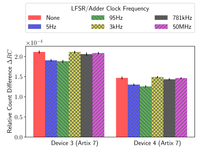
To test whether an active protection mechanism can disrupt the channel through additional dynamic activity on the device, we measure the strength of the channel in the presence of large, competing circuits which are both in- and out-of-sync with respect to the transmissions. We synthesize 2 large 4096-bit adders, adding different parts of a bitstream produced by a Linear Feedback Shift Register (LFSR). As a result, both the addends and the sums change every time the LFSR produces a new bit. The bits of each sum are then XORed together and drive 2 LEDs for additional current draw. We run the experiment on two Artix 7 Nexys 4 boards, for a transmitter and receiver using 10 longs each.
In order to test transmission and reception under surrounding activity of different switching frequencies, we vary how often the LFSR produces new values by dividing the clock driving it by , for , giving us frequencies of 5Hz – 50MHz. The results for the two devices, including the base case of no adders and LFSRs, are summarized in Figure 13, showing that additional activity cannot disrupt the transmissions. However, we note some correlation between the frequency of the activity and the corresponding count difference. The resulting change is not sufficient to hinder transmission, but can be used by the adversary to detect the level of activity on the device, a technique already used by Hardware Trojan detectors (Kelly et al., 2015; Zhang and Tehranipoor, 2011).
10. Exploiting the Leakage
In this section we discuss exploiting the information leakage from a theoretical perspective. In some cases (such as that of Figure 2), a threshold is sufficient for distinguishing between 0s and 1s, but in other setups (such as that of Figure 5), this separation might not be as clear: the RO frequency may drift due to changes in environmental conditions, such as temperature and voltage variation. We first detail an encoding scheme that enables high-bandwidth covert transmissions (Section 10.1), and then explain how to eavesdrop on dynamic signals through repeated measurements (Section 10.2).
10.1. Covert Transmissions
To overcome the hurdle posed by local fluctuations, we propose a Manchester encoding scheme, where 0s are transmitted as the pair , and 1s as the pair . Since every pair contains each bit once, one can decode the received pair as a 0 if and as a 1 otherwise. Using this scheme, transmissions lasting using 2 longs as well as transmissions lasting using of a long are both recovered with accuracies of 99.0 – 99.9%, without employing any error correction algorithms. Under this encoding scheme, the bandwidth of the channel is .
To further distinguish between noise and legitimate transmissions, we can introduce -bit start- and end-of-frame patterns. Assuming that the probability that when no transmission is taking place is (i.e., each measurement is equally likely to be interpreted as a 0 or a 1), then the probability that noise is interpreted as a start-of-frame when no transmission is taking place is . As the channel is resilient to noise (also see Section 9), noise will not accidentally end a transmission early or introduce additional errors while a transmission is taking place. can thus be chosen based on the desired application guarantees, which can include additional checksums for error detection and correction. In particular, line codes such as 8b/10b provide single-bit error-detection capabilities, and aid in clock recovery, making them ideal for such an application. The bandwidth of the channel is then reduced to .
10.2. Signal Exfiltration
If an adversary is merely eavesdropping on nearby signals, it is unlikely that they will remain constant throughout the period of measurement. However, as shown in Section 6.2 (Figure 6), the delay of the long wire depends only on the proportion of time for which the nearby wire is carrying a 1, and not its switching frequency. This fact reveals the Hamming Weight of the transmission during the measurement period. By repeating measurements with a sliding window, an eavesdropping adversary can fully recover nearby dynamic signals such as cryptographic keys with high probability.
Suppose the adversary wishes to recover an -bit key , and assume that in one period of measurement, the long wire carries consecutive bits of the key. We assume initially that is an integer multiple of the measuring window , and explain how to remove this assumption in Appendix A. By making repeated measurements of different but overlapping windows, as shown in Figure 14, the adversary can recover the key with high probability. Specifically, assume the Hamming weight (measured by the RO count) of the first key bits to (window ) is , and that the Hamming weight of bits through (window ) is . Then, if (within some device-dependent tolerance), we can conclude that . If then and , while if then and . By comparing the next count to , one can determine the values of and , and, more generally, by repeating this process, one can determine the relationship between and .
Assuming a randomly generated key, the probability that for is . The probability that all of , , …, are equal is , since there are such pairs. The probability that at least one of the bits in is different than the rest is thus . If at least one is different, we can recover all of these bits. Repeating this argument for all possible remainders , the probability of recovering the entire key is
| (2) |
by Bernoulli’s inequality. Even if it might appear counter intuitive, the expression shows that longer keys are easier to recover than short keys. A larger window size relative to the key length makes recovering the key harder as there are fewer measurements over the length of the key. For the same reason, a longer key will increase the recovery probability. This means that asymmetric keys, e.g., those used for signature verification are relatively easy to recover, as they are typically much longer than symmetric keys.

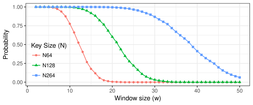
Figure 15 shows the probability of successfully recovering all bits of a key as a function of the window size . A window of 10 bits can fully recover a key of size 64 with 78% probability, while a 30-bit window can recover a 264-bit key with 87% probability. Figure 15 only shows the probability for full recovery, i.e., if all but one bit is recovered we still consider it a failure. However, the above procedure can still reveal a lot about the key, even when it does not recover it fully: in the worst case (if the entire key consists of a repetition of its first bits), our approach reduces the guessing space from to possibilities.
Extending the procedure to use multiple window lengths, we can recover any key pattern with probability 1, except for when all key bits are the same (i.e., all ones or all zeroes). This full recovery can be achieved using a total of just full passes over the key. Appendix A gives an expression for the exact probability of full key recovery for both single and multiple window sizes.
11. Discussion
We structure our discussion in three parts: the channel itself (Section 11.1), the cause of the information leakage (Section 11.2), and potential defenses (Section 11.3).
11.1. The Channel
The channel characterized in the previous sections does not require any modifications to the device or special tooling, allowing an adversary to distribute it as IP blocks. The only routing that needs to be specified is the use of the long wires, and the only placement constraint is that the receiver and transmitter longs are adjacent. The channel requires very little logic: the entire setup including the signal generation and measurement portions uses just 71 lookup tables (LUTs) and 66 registers, excluding resources taken up by ChipScope to transfer the measurements to a PC for analysis. As an example, our channel would only use 0.2% of the 33,000 LUTs used in the open-source N200/N210 Universal Software Radio Peripheral (USRP) software-defined radio project (Research, 2017a).
The USRP source codebase (Research, 2017b) illustrates how IP from different organizations makes it into a project: USRP uses code from Ettus Research, Xilinx, Easics NV, and OpenCores (written by different authors). Since third-party code is a necessity, and as modern IP blocks can be quite large, the potential for unintended interaction between different cores increases. An adversary can exploit the routing algorithms, which are forced to route through otherwise monolithic black-box IPs due to resource constraints, enabling his blocks to communicate covertly or eavesdrop on nearby signals.
As ring oscillators have legitimate uses, from thermal and device health monitors (Boemo and López-Buedo, 1997; Zick and Hayes, 2012) to Hardware Trojan detectors (Kelly et al., 2015; Zhang and Tehranipoor, 2011), TRNGs (Vasyltsov et al., 2008), and PUFs (Maiti et al., 2010), the adversary can make dual-use transmitters and receivers. The channel we identify exists whether transmissions are intentional or not, and is a threat when an adversary controls one or more IP cores. Unintentional transmissions pose new risks for multi-user scenarios, including FPGA/CPU hybrids and cloud infrastructures offering FPGA solutions. In these setups, an adversarial receiver can be placed next to long wires used by other third-party vendors and eavesdrop on the signals carried by them. The same mechanism can also be used for legitimate purposes such as watermarks and no-contact debugging taps.
11.2. Leakage Cause
So far, we have focused on the novelty and applicability of the phenomenon presented, rather than its cause. In Section 6.3, we showed that the phenomenon depends on the use of the long wires, and not the switching activity of circuits, which decreases rather than increases ring oscillator frequency. The only other work which deals with long wires delays is (Gag et al., 2012), where a RO with a long wire was placed next to other long wires carrying signals which where either equal to the RO signal or opposing it. It was shown that when a nearby long wire has the same value as the RO wire, the frequency of the RO is higher compared to the RO frequency when the nearby long wire has the opposite value (i.e., if the current value on the RO long wire is a 1, the value on the nearby wire is 0 and vice versa). The work in (Gag et al., 2012) necessitates that the signal of the RO and the nearby wire be in sync, so the wires were directly connected, and static patterns which are independent of the RO signal were not tested. By contrast, in our work, we showed that nearby wires are influenced even when there is no connection between the transmitter and the receiver, and even when the transmitted value remains constant during the measurement period. These two properties can be exploited in constructing a communication channel.
Although (Gag et al., 2012) broadly categorized their observations as “capacitive crosstalk”, it made no attempt to precisely determine the physical cause behind it. This would indeed be difficult without design information such as physical layout and process-specific parameters. This “lack of electrical detail” on FPGAs is, in fact, well-known and has been identified by multiple authors (Al-Assadi and Kakarla, 2008; Anderson and Najm, 2004; Ran and Marek-Sadowska, 2003; Su et al., 2000; Wilton, 2001).
As a result, whether the effect we have found exists due to drive-strength issues, electromagnetic emissions, or some other property of FPGAs remains an open question. It is even possible that the wires themselves might not be the cause of the issue, but that the buffers driving them share local connections to the power network. However, without more specialized equipment to x-ray the chips to further narrow down the potential causes, we cannot determine the precise cause, or even whether ASICs would be affected.
Overall, the characterization of the channel is valuable even without access to these details, since we have shown it to always be present and easily measurable on off-the-shelf devices without special modifications. FPGA users cannot alter the electrical behavior of the device, but can only influence how circuits are mapped onto the FPGA. As a result, FPGA circuit designers cannot change the existence of the channel, and need to be aware of the communication and exfiltration capabilities that this channel introduces.
11.3. Defense Mechanisms
Section 9 showed that one cannot detect transmissions from a distance , and that spurious activity (in the form of adders and additional current draw) does not eliminate the transmission channel. Hence, defense mechanisms need to protect a design before it is loaded onto the FPGA. Since long wires are an integral part of the reconfigurable FPGA fabric, detecting the transmitter is not easy: the long can be used as part of the connections within an IP block, carrying sensitive information. Routing algorithms thus need to be modified to account for this information leakage, by introducing directives which mark signals, or even entire blocks as sensitive. The tools then need to add “guard wires”, by either leaving the four nearby long wires unoccupied, or by occupying them with compiler-generated random signals. We note that even though this approach will prevent the leakage from occurring, it is particularly taxing for dense designs, and can make placement and routing more time-consuming, or even lead to timing violations.
Designers using unpatched tools need to be aware of this source of leakage, and must either manually look for long-wires post-routing, explicitly add guard wires, or, more generally, specify placement and routing constraints for both highly-sensitive signals, and untrusted third-party blocks. Overall, better defense mechanisms for future FPGA generations are needed at the architectural level, and require a deeper understanding of the cause of this phenomenon.
12. Related Work
Research on side- and covert-channels on FPGAs and other embedded devices has primarily focused on communications between the device and the outside world. Techniques include varying the power consumption of a device and measuring the impulse response (Ziener et al., 2010), changing how much Electromagnetic Interference is emitted by the device (Bauer et al., 2016), or, in the other direction of communication, measuring voltage (Samarin et al., 2016) and temperature changes (Sun et al., 2011). These side-channels can be employed in the context of creating Hardware Trojans (HTs) (Lin et al., 2009), or as ways to watermark circuits and offer IP protection (Becker et al., 2010; Samarin et al., 2016).
Many of these circuits employ ring oscillators, exploiting their dependence on Process, Voltage, and Temperature (PVT) variations (Hajimiri et al., 1999). ROs are primarily used on the receiving end, but they can also be used to transmit information by causing changes in temperature (Iakymchuk et al., 2011). This technique allows communications between blocks on the same device, under a threat model similar to ours.
Ring oscillators have also been used in security-sensitive applications, including True Random Number Generators (TRNGs) (Vasyltsov et al., 2008) and Physically Unclonable Functions (PUFs) (Maiti et al., 2010). Consequently, any mechanism which can be used to manipulate or bias their frequency can also be used to attack these applications. Besides the technique introduced in this paper, prior work has influenced the delays of ROs by altering the power supply (Markettos and Moore, 2009) and by injecting EM signals (Bayon et al., 2012), resulting in low entropy and cloneability.
As explained in Section 11.2, a switching pattern in sync with the RO’s signal increases the RO’s oscillation frequency by 1-9% compared to a pattern that opposes it (Gag et al., 2012). To achieve this synchronization, however, requires the transmitter to be connected to the output of one of the RO’s stages. As a result, as presented, this mechanism cannot be used directly for side-channel communication or to reliably attack the ring oscillator, due to the high accuracy of prediction required for the frequency and phase of the oscillator.
Emphasis has also been placed on using networks of ROs to detect Hardware Trojans on a device (Kelly et al., 2015; Zhang and Tehranipoor, 2011). The dynamic power consumed by HTs results in a voltage drop that lowers the RO frequencies compared to those in the Trojan-free “golden” IC, making them detectable. Such prior work depends on the effect switching activity has on the frequency of ROs to detect HTs. As shown in Figure 7, when using short wires, we were able to reproduce the prior effect, where only the number of bit transitions, and not the actual bits themselves, were the cause for the RO frequency drop. However, this no longer holds for long wires: the frequency increases based on the duration for which a 1 is transmitted, irrespective of the dynamic activity. As a result, the channel depends on a fundamentally different phenomenon, which uses the values carried on the wires themselves, and not their transitions.
Prior work (Moradi, 2014) has shown that to detect slowly-changing signals, very large circuits (over 14k registers) or long measurement times (2.5h) are needed, in addition to external measurement equipment, and special modifications to the device. By contrast, our work only uses small on-chip circuits, without any special control over voltage or temperature conditions. We can distinguish between the values of signals which remain constant (i.e., have no switching activity) during our period of measurement, which is as low as , a measurement period which is also a lower bound for on-chip HT detection using ROs (Lecomte et al., 2015).
13. Conclusion
We demonstrated the existence of a previously unexplored phenomenon on FPGA devices, that causes the delay of so called “long wires” to depend on the logical state of nearby long wires, even when the driven value remains constant. The effect is small, but surprisingly resilient, and measurable within the device by small circuits even in the presence of environmental noise, and without any modifications to the FPGA. We use this phenomenon to create a communication channel between circuits that are not physically connected. As designs often incorporate circuits from multiple third-parties, this channel can break separation of privilege between IP cores of different trust levels, or enable communication between distinct cores in multi-user setups. Such use-cases are increasingly common as FPGAs and CPUs become integrated, and as FPGAs become available on public cloud infrastructures. The same mechanism can also be used to eavesdrop and recover keys with high probability even when the signals change during the period of measurement, or to implement a no-contact debugging tap or watermark scheme. In our prototype implementation, the channel has a bandwidth of up to , and we can recover over 99% of the transmitted bits correctly using a Manchester encoding scheme. We showed that the phenomenon is present in three generations of Xilinx FPGAs, and that the channel can be implemented in a variety of arrangements, including different locations, orientations, and with multiple transmitting circuits present. The strength of the phenomenon scales linearly with the number of wires used, and also dominates a competing effect caused by switching activity.
References
- (1)
- Al-Assadi and Kakarla (2008) W. K. Al-Assadi and S. Kakarla. 2008. A BIST Technique for Crosstalk Noise Detection in FPGAs. In Defect and Fault Tolerance of VLSI Systems.
- Anderson and Najm (2004) Jason H. Anderson and Farid N. Najm. 2004. Interconnect Capacitance Estimation for FPGAs. In Asia and South Pacific Design Automation Conference (ASP-DAC).
- Bauer et al. (2016) J. Bauer, S. Schinzel, F. Freiling, and A. Dewald. 2016. Information leakage behind the curtain: Abusing anti-EMI features for covert communication. In Hardware Oriented Security and Trust (HOST).
- Bayon et al. (2012) Pierre Bayon, Lilian Bossuet, Alain Aubert, Viktor Fischer, François Poucheret, Bruno Robisson, and Philippe Maurine. 2012. Contactless Electromagnetic Active Attack on Ring Oscillator Based True Random Number Generator. In Constructive Side-Channel Analysis and Secure Design (COSADE).
- Becker et al. (2010) G. T. Becker, M. Kasper, A. Moradi, and C. Paar. 2010. Side-channel based watermarks for integrated circuits. In Hardware-Oriented Security and Trust (HOST).
- Boemo and López-Buedo (1997) Eduardo Boemo and Sergio López-Buedo. 1997. Thermal monitoring on FPGAs using ring-oscillators. In Field-Programmable Logic and Applications (FPL).
- Chakraborty et al. (2013) R. S. Chakraborty, I. Saha, A. Palchaudhuri, and G. K. Naik. 2013. Hardware Trojan Insertion by Direct Modification of FPGA Configuration Bitstream. IEEE Design Test 30, 2 (April 2013), 45–54.
- Gag et al. (2012) M. Gag, T. Wegner, A. Waschki, and D. Timmermann. 2012. Temperature and on-chip crosstalk measurement using ring oscillators in FPGA. In Design and Diagnostics of Electronic Circuits Systems (DDECS).
- Hajimiri et al. (1999) A. Hajimiri, S. Limotyrakis, and T. H. Lee. 1999. Jitter and phase noise in ring oscillators. IEEE Journal of Solid-State Circuits 34, 6 (Jun 1999), 790–804.
- Huffmire et al. (2008) T. Huffmire, B. Brotherton, T. Sherwood, R. Kastner, T. Levin, T. D. Nguyen, and C. Irvine. 2008. Managing Security in FPGA-Based Embedded Systems. IEEE Design Test of Computers 25, 6 (Nov 2008), 590–598.
- Iakymchuk et al. (2011) T. Iakymchuk, M. Nikodem, and K. Kepa. 2011. Temperature-based covert channel in FPGA systems. In Reconfigurable Communication-Centric Systems-on-Chip (ReCoSoC).
- Kelly et al. (2015) Shane Kelly, Xuehui Zhang, Mohammed Tehranipoor, and Andrew Ferraiuolo. 2015. Detecting Hardware Trojans using On-chip Sensors in an ASIC Design. Journal of Electronic Testing 31, 1 (2015), 11–26.
- Korf et al. (2011) S. Korf, D. Cozzi, M. Koester, J. Hagemeyer, M. Porrmann, U. Rückert, and M. D. Santambrogio. 2011. Automatic HDL-Based Generation of Homogeneous Hard Macros for FPGAs. In Field-Programmable Custom Computing Machines (FCCM).
- Krieg et al. (2016) Christian Krieg, Clifford Wolf, and Axel Jantsch. 2016. Malicious LUT: A Stealthy FPGA Trojan Injected and Triggered by the Design Flow. In International Conference on Computer-Aided Design (ICCAD).
- Lavin et al. (2013) Christopher Lavin, Brent Nelson, and Brad Hutchings. 2013. Impact of hard macro size on FPGA clock rate and place/route time. In Field Programmable Logic and Applications (FPL).
- Lavin et al. (2010) Christopher Lavin, Marc Padilla, Subhrashankha Ghosh, Brent Nelson, Brad Hutchings, and Michael Wirthlin. 2010. Using Hard Macros to Reduce FPGA Compilation Time. In Field Programmable Logic and Applications (FPL).
- Lavin et al. (2011) Christopher Lavin, Marc Padilla, Jaren Lamprecht, Philip Lundrigan, Brent Nelson, and Brad Hutchings. 2011. HMFlow: Accelerating FPGA Compilation with Hard Macros for Rapid Prototyping. In Field-Programmable Custom Computing Machines (FCCM).
- Lecomte et al. (2015) M. Lecomte, J. J. A. Fournier, and P. Maurine. 2015. Thoroughly analyzing the use of ring oscillators for on-chip hardware trojan detection. In ReConFigurable Computing and FPGAs (ReConFig).
- Lin et al. (2009) Lang Lin, Markus Kasper, Tim Güneysu, Christof Paar, and Wayne Burleson. 2009. Trojan Side-Channels: Lightweight Hardware Trojans through Side-Channel Engineering. In Cryptographic Hardware and Embedded Systems (CHES).
- Maiti et al. (2010) A. Maiti, J. Casarona, L. McHale, and P. Schaumont. 2010. A large scale characterization of RO-PUF. In Hardware-Oriented Security and Trust (HOST).
- Markettos and Moore (2009) A. Theodore Markettos and Simon W. Moore. 2009. The Frequency Injection Attack on Ring-Oscillator-Based True Random Number Generators. In Cryptographic Hardware and Embedded Systems (CHES).
- Merli et al. (2010) Dominik Merli, Frederic Stumpf, and Claudia Eckert. 2010. Improving the Quality of Ring Oscillator PUFs on FPGAs. In Workshop on Embedded Systems Security (WESS).
- Moradi (2014) Amir Moradi. 2014. Side-Channel Leakage through Static Power. In Cryptographic Hardware and Embedded Systems (CHES).
- Ran and Marek-Sadowska (2003) Y. Ran and M. Marek-Sadowska. 2003. Crosstalk noise in FPGAs. In Design Automation Conference (DAC).
- Research (2017a) Ettus Research. 2017a. N200/N210. https://kb.ettus.com/N200/N210. (2017). Accessed: 2017-05-17.
- Research (2017b) Ettus Research. 2017b. The USRP Hardware Driver FPGA Repository. https://github.com/EttusResearch/fpga. (2017). Accessed: 2017-05-17.
- Samarin et al. (2016) P. Samarin, K. Lemke-Rust, and C. Paar. 2016. IP core protection using voltage-controlled side-channel receivers. In Hardware Oriented Security and Trust (HOST).
- Shila et al. (2015) Devu Manikantan Shila, Vivek Venugopalan, and Cameron D. Patterson. 2015. Unraveling the Security Puzzle: A Distributed Framework to Build Trust in FPGAs. In Network and System Security (NSS).
- Smith and Ventrone (2011) J.R. Smith and S.T. Ventrone. 2011. Multi-processor chip with shared fpga execution unit and a design structure thereof. (Dec. 15 2011). https://www.google.co.uk/patents/US20110307661 US Patent App. 12/796,990.
- Su et al. (2000) Chauchin Su, Yue-Tsang Chen, Mu-Jeng Huang, Gen-Nan Chen, and Chung-Len Lee. 2000. All digital built-in delay and crosstalk measurement for on-chip buses. In Conference on Design, Automation and Test in Europe (DATE).
- Sun et al. (2011) Ji Sun, Ray Bittner, and Ken Eguro. 2011. FPGA Side-channel Receivers. In Field Programmable Gate Arrays (FPGA).
- Tehranipoor and Koushanfar (2010) M. Tehranipoor and F. Koushanfar. 2010. A Survey of Hardware Trojan Taxonomy and Detection. IEEE Design Test of Computers 27, 1 (Jan 2010), 10–25.
- Vasyltsov et al. (2008) Ihor Vasyltsov, Eduard Hambardzumyan, Young-Sik Kim, and Bohdan Karpinskyy. 2008. Fast Digital TRNG Based on Metastable Ring Oscillator. In Cryptographic Hardware and Embedded Systems (CHES).
- Wilton (2001) Steven J. E. Wilton. 2001. A Crosstalk-aware Timing-driven Router for FPGAs. In Field Programmable Gate Arrays (FPGA).
- Zhang and Tehranipoor (2011) X. Zhang and M. Tehranipoor. 2011. RON: An on-chip ring oscillator network for hardware Trojan detection. In Design, Automation and Test in Europe (DATE).
- Zick and Hayes (2012) Kenneth M. Zick and John P. Hayes. 2012. Low-cost Sensing with Ring Oscillator Arrays for Healthier Reconfigurable Systems. ACM Trans. Reconfigurable Technol. Syst. 5, 1 (March 2012), 1–26.
- Ziener et al. (2010) D. Ziener, F. Baueregger, and J. Teich. 2010. Using the Power Side Channel of FPGAs for Communication. In Field-Programmable Custom Computing Machines (FCCM).
Appendix A Generalizing Signal Exfiltration
In this section we explain how to remove the assumption that the key size is a multiple of the window size , and how to fully recover keys by varying the window size.
To start with, if , with , the probability that the bits in , , , are the same is for , since . For this probability is , as . This allows us to adjust Equation (2) to
| (3) |
In particular, if is a multiple of , then , so the above expression reduces to (2).
The expression is valid for any length , removing the requirement that is an integer multiple of . The lower bound on is necessary if we wish to recover the first bits of the key, as we need to have for each with in order to have elements in .
Suppose that the original measurements were not able to recover the bits in because they were all identical. By repeating measurements with a window of size , the algorithm either recovers all bits in the sequence , , , or shows that they too are identical (here, under the assumption that ).
In the first case, the algorithm recovers , and hence since all its bits are identical. In the second case, where all bits in are also identical, the entire key consists of a single repeated bit (i.e., all ones or all zeroes). This is because , and , etc. Note that the size of might be too small to cover the all the residues by itself, but varying allows us to recover all of with probability 1 if there are at least 2 different bits in the key, or to determine that the key consists of the same repeated bit.
For a window of size , we need measurements, but this can be accomplished in only independent runs of the experiment. Run is responsible for collecting the measurements for the parts of the key that start with for some . For example, run measures the Hamming weight of the key bits , and , etc. As there is no overlap in the bits used, these measurements can be completed in a single run. Thus, using both window sizes, and to fully determine all the bits of a key, one needs to take
measurements over just
runs, showing that this key-recovery algorithm is efficient. In other words, the key only needs to be repeated times to be fully leaked.