Multi-mirror imaging optics for low-loss transport of divergent neutron beams and tailored wavelength spectra
Abstract
A neutron optical transport system is proposed which comprises
nested short elliptical mirrors located halfway between two common focal
points M and M’. It images cold neutrons from a diverging beam or a source
with finite size at M by single reflections onto a spot of similar size at
M’. Direct view onto the neutron source is blocked by a central absorber
with little impact on the transported solid angle. Geometric neutron losses
due to source size can be kept small using modern supermirrors and distances
M-M’ of a few tens of metres. Very short flat mirrors can be used in
practical implementations. Transport with a minimum of reflections remedies
losses due to multiple reflections that are common in long elliptical
neutron guides. Moreover, well-defined reflection angles lead to new
possibilities for enhancing the spectral quality of primary beams, such as
clear-cut discrimination of short neutron wavelengths or beam monochromation
using bandpass supermirrors. Multi-mirror imaging systems may thus
complement or even replace ordinary neutron guides, in particular at the
European Spallation Source.
Keywords: neutron optics, supermirror, bandpass mirror, cold neutrons, neutron EDM
1 Introduction
Physics with slow neutrons at research reactors and spallation sources can hardly be imagined without devices for neutron transport. Thanks to the invention of neutron guides [1] intense beams have become available over metres away from a neutron moderator. As a result, many experiments can be performed simultaneously at a single source and well shielded against radiation backgrounds. The physical principle of a neutron guide is total reflection by a surface of a medium with a positive neutron optical potential. For neutrons with wavelength this requires the normal component of the wave vector with modulus to stay below a critical value characteristic for the mirror material. Nickel with natural isotopic composition is well suited, and enriched 58Ni even more so, for which is particularly large. For thermal and cold neutrons, corresponds to a small critical angle of reflection that is given by
| (1) |
This defines a ”mirror constant” with value rad/nm for natural Ni.
Advances in performance have been achieved with the so-called supermirror. This device relies on coherent wave superpositions in a superlattice formed by a sequence of bilayers of two materials with very different neutron optical potentials (most often Ni and Ti) [2]. Broad-band supermirrors became popular in neutron physics in the 1980’s soon after Otto Schärpf started a first large-scale production for a neutron scattering instrument with wide-angle polarisation analysis [3]. An ideal device would extend by a factor the range for which reflection from a simple mirror made of natural Ni is nearly lossless. Correspondingly, the neutron flux at the end of a long supermirror guide would scale with as the solid angle increases. In real supermirrors, however, neutron losses occur due to roughness of the layer interfaces and due to absorption. For simulations of neutron transport efficiencies, one usually describes their reflectivity by
| (2) |
which includes a linear drop from unity at down to a value at . Commercially available supermirrors have reflectivity % at . Hence, even if a neutron requires only a few reflections with in the range , its probability to arrive at the end of a long guide may be quite low.
The concept of a ballistic neutron guide mitigates this problem [4]. Here, the guide cross section first increases linearly with the distance from the source, then stays constant in a second and usually much longer section, and finally converges linearly back to its initial size. The corresponding phase space transformations of the beam reduce the total number of reflections. Moreover, the reduced beam divergence in the straight guide section necessitates only a coating with lower which costs less and has a higher reflectivity of typically % at a standard . A ballistic guide was first implemented in the fundamental-physics beamline PF1B at the ILL [5, 6]. In the meantime, extensions of the concept have become popular, including parabolically and elliptically shaped guides [7, 8].
It should be noted that neutron guides are not imaging devices and typically transport neutrons by many reflections. This contrasts with grazing-angle imaging systems that were first developed for x-rays, such as Wolter optics which focus a parallel beam by double reflections off a parabolic mirror combined with a hyperbolic or elliptical one. Such systems are also feasible for slow neutrons [9], for which a microscope based on three nested coaxial Wolter mirrors has been demonstrated [10]. Here a mirror system is proposed for imaging neutrons under large solid angle from an extended neutron source or the end of a neutron guide onto a target area of similar size. Based on single reflections, the imperfect mirror reflectivity in the range has a rather limited impact so that one may expect significant gains with respect to long guides. Moreover, a well defined angle of incidence on every mirror surface element offers interesting new opportunities for tailoring and monochromation of primary beams.
2 Neutron optical transport in an elliptical guide
Let us first recall mathematical properties of an elliptical mirror and point out why a long elliptical neutron guide is a non-imaging device. In a plane with cartesian coordinates and ,
| (3) |
describes an ellipse with long and short axes and , respectively. The latter are related with the distance between the two focal points according to
| (4) |
It is well known that a single specular reflection off an ellipse maps a straight ray emitted in any direction from the first focal point M located at onto the second focal point M’ at . For cold neutrons with not excessively large wavelength, the maximum reflection angle does not exceed a few degrees even for a large- supermirror. Elliptical neutron mirrors are therefore truncated to , and guides usually ”narrow” () and ”long” ().
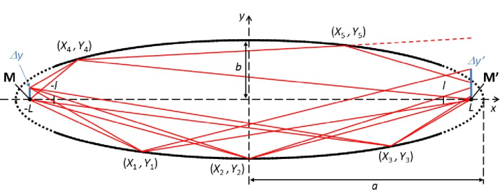
It is easy to see that for a long elliptical guide the mapping between focal points does not lead to an optical image of an extended source. As illustrated in Fig. , a ray starting at with a lateral offset and reflected at a point arrives at with an offset of
| (5) |
A long mirror reflects within a wide range of and hence superposes images with widely varying magnifications . Reflections at are focusing, , as shown for example with the reflection point . They lead to an increase of flux density at M’. In the opposite case, [e.g., for reflection at ], the mirror magnifies the source, thus reducing the corresponding flux density. The latter case represents a vast majority of neutrons in a long guide, because the ratio of ranges of unidimensional angular acceptance, , is usually much larger than unity and enters squared in the solid angle. The spatial intensity distribution at M’ thus becomes widened and the flux density reduced with respect to M. In addition, for a significant fraction of neutrons the magnification becomes so large that they impinge at least a second time on the mirror [such as the ray from to ]. This leads not only to increased losses due to imperfect mirror reflectivity, but also to complex structures in the divergence distribution as observed in Monte-Carlo simulations [11]. Indeed, these authors concluded that ”transport of neutrons by realistic elliptic guides usually involves many reflections, contrary to the usual expectations”. They also state that multiple reflections become increasingly common with increasing guide length. A mirror system based on single neutron reflections may therefore lead to improved beam transport efficiency. The next section discusses such a system.
3 Elliptical multi-mirror system
The proposed neutron optical system is shown in Fig.. It consists of nested short elliptical mirrors with common length . They are located in the plane halfway between M and M’ which are the common focal points of all ellipses. A central absorber blocks the direct view from M’ to M. According to Eq. 5 and in contrast to a single long mirror, one obtains a well-defined image at M’ which is weakly blurred due to magnifications being limited to a narrow range . Focusing is also possible, by placing elliptical mirrors closer to the point M’. However, this reduces the solid angle subtended from the point M. Compared to a guide starting close to a source, mirrors situated at a large distance (i.e., ) are much less exposed to damaging radiation. A clear spatial separation from the source environment also facilitates independent maintenance of neutron-optical and in-pile components, including exchange of beam tubes.
The mirror system may be implemented either with toroidal or with translational, ”planar” symmetry. In the former case, the device is rotationally symmetric about the axis; each mirror surface is a section of an ellipsoid of revolution ( and in Eq. 3 are then taken as the axial and radial components in cylindrical coordinates, respectively). A single reflection transports a neutron from M to M’. In the planar case, the mirrors have a local translational symmetry along the axis (taken together with and as Cartesian coordinates). Neutrons undergo a single reflection with momentum transfer in the plane, but additional mirrors are needed to refocus or guide them in the orthogonal direction. For instance, adding a second planar multi-mirror optics rotated by degrees about the axis creates a ”double planar” system in which two imaging reflections occur, one for each transverse dimension.
In contrast to grazing-angle optics for x-rays, toroidal mirrors for imaging slow neutrons over long distances may exhibit significant chromatic aberrations due to gravity. These also occur in the aforementioned double planar system, obviously without affecting reflections on vertical mirrors. Gravity has practically no relevant influence in a hybrid system consisting of planar multi-mirror optics combined with simple or ballistic reflective boundaries in the vertical dimension . These mirrors, projected onto the plane, must cover the whole area defined by the outermost rays in Fig. . Hybrid systems seem best suited when a large beam divergence can be accepted only in one dimension. For instance, neutron scattering instruments possessing a detector array with high unidimensional angular resolution require a tight collimation within the scattering plane. An anisotropic beam divergence may also originate from the source due to moderator shape and/or geometrical constraints on beam tubes. Another interesting application of hybrid systems is large-angle deviation of beams with low-to-medium divergence, given that space restrictions for instruments at reactor and spallation neutron sources are often an issue. In this case one uses only half of the device shown in Fig. .
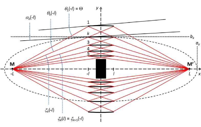
For the mathematical construction let us define as the angle between the axis connecting the focal points and a straight line from M to a point on the ellipse with index , as shown in Fig. . The angle of reflection at then follows from
| (6) |
where the angle is related to the slope of the tangent to the ellipse according to
| (7) |
Notice that all angles are taken as positive except , which becomes negative for . These definitions provide a consistent common description for the mirror systems with toroidal and planar symmetry. The angle subtended at a focal point by an elliptical section between and is given by
| (8) |
For a point source at M this defines a range of angles that the mirror can accept. Using Eqs. 6 and 7, the angles of reflection for this mirror follow from
| (9) |
Hence, a smaller value of produces a smaller spread of reflection angles.
The nested ellipses can be constructed as follows. Note first that
| (10) |
according to Eq. 3 applied to the ellipse . The straight line connecting the focal point M with the rear end point of the mirror is required to coincide with the front end point of the mirror . This provides the condition [note that ]
| (11) |
where the right side follows from Eqs. 6 and 10. The mirrors are defined recursively by incrementing in unit steps in Eqs. 10 and 11. The outermost ellipse is defined by a largest reflection angle that occurs at its ends, . This leads us to
| (12) |
Table lists parameters of the mirrors of a representative assembly for neutron transport to a position m away from a source.
The total number of mirrors corresponds to the number of recursions. For the toroidal case, counts the rings of mirrors, while for the planar system it counts the mirrors on one side of the central absorber. In the limit one can estimate as follows without actually performing the recursion. Using Eqs. 10 and 11, the channel width between the mirrors and is given by
| (13) |
where the expression on the right side is valid with a relative error of order . For we may also write . Hence,
| (14) |
so that
| (15) |
The number of mirrors needed to cover the range of angles defined by the parameters and of the outer- and innermost ellipses, respectively, is thus given by
| (16) |
As a new feature for neutron optical transport systems (and in contrast to neutron guides), the multi-mirror optics discriminates short-wavelength neutrons. These are often a nuissance and lead for instance to second-order Bragg diffraction in crystal monochromators. While a Bragg filter made of compressed crystallites of a weakly absorbing material can remove this spectral component, some useful neutrons are lost as well. Short-wavelength neutrons also generate scattering backgrounds that, due to the law for neutron absorption, require thicker shielding. A multi-mirror imaging system supersedes Bragg filters and improves background conditions. Due to reflection angles in a narrow range about a finite value, each mirror provides a sharp cutoff. Moreover, the spectrum reflected from every mirror can be tailored to the same cutoff wavelength , which is defined by Eq. 1 (replacing by to account for the extended reflectivity of supermirrors) and the geometric definition of the reflection angle on the mirror . It thus satisfies the relationships
| (17) |
In practice, one could first select a value for , then choose an -value for the outermost mirror and finally determine the values of all the other mirrors, while keeping constant the ratios (this has been done in Table ). Obviously, a smaller spread of reflection angles on each mirror (see Eq. 9) leads to a better definition of . This requires the mirrors to be shorter (and thus a larger number of them according to Eq. 16).
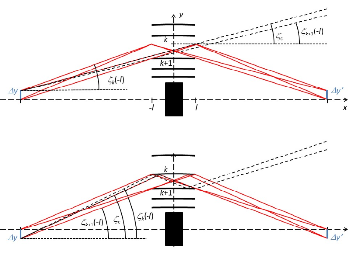
Next we discuss neutron losses due to finite size of the source at M. We call them ”geometrical” for distinction from losses due to imperfect mirror reflectivity. For simplicity let us consider the case of the planar system. As sketched in the upper part of Fig. , neutrons starting from the point with a positive velocity component may fly through the mirror channel without any reflection. For a starting point , shown in the lower part of Fig. , neutrons may become reflected twice. For each channel one can quantify a transport loss associated with these effects. For a positive lateral displacement (with ) this is given by
| (18) |
where is a critical angle that separates a range of angles for which no reflections occur, , from the range corresponding to the desired single reflections. For the fractional transport loss is given by
| (19) |
where is the range of angles for which double reflections are possible. Most of the angles can be directly read from Fig. , whereas in the case needs to be calculated. For one obtains, independent of the sign of displacement,
| (20) |
The innermost mirror channel thus has the largest losses. For a source of a given size, geometrical losses decrease when the mirror system is enlarged. Keeping the ratios and constant, the angular acceptance stays approximately constant (exactly so for a point source), while from Eq. 20 decreases with increasing . For a system with given parameters , , , and designed for a common , we have according to Eq. 17. Hence, a system for cold neutrons is shorter than an equivalent system for thermal neutrons with same geometrical losses. For too large , however, the performance may become limited by mirror waviness. Note finally that does not depend on (in the limit ). Systems consisting of very short, flat mirrors locally approximating the elliptical surfaces are thus a viable possibility.
A first estimate of the efficiency of a mirror system involves the solid angle for neutron transport. For a sufficently large toroidal system it is characterised by the angles and of the outer- and innermost rays shown in Fig. , i.e.
| (21) |
For a planar system with nested mirrors one may define a unidimensional angular acceptance
| (22) |
Determination of the transport solid angle also requires knowledge of the angular acceptance in the orthogonal transverse direction. For calculation of the transport efficiency, Eqs. 21 and 22 still need to be corrected for imperfect mirror reflectivities and for the geometrical losses described before. The simple kinematics of single reflections facilitates numeric calculations without simulating trajectories. For a known source this should provide fairly accurate predictions of neutron fluxes.
4 Wavelength selective neutron transport optics
When neutrons within a limited range of wavelengths are needed for a specific application, the multi-mirror systems described before can be equipped with bandpass supermirrors for transport of the desired spectrum. In particular, this includes quasi-monochromatic spectra peaked at some value with a spread of a few percent or less. For a discussion of the principle let us describe their reflectivity approximately by
| (23) |
where the bandpass reflectivity is separated from a region of total reflectivity at low . A bandpass supermirror requires fewer layers than a broad-band supermirror with same value. It therefore has less absorption and can be produced with less roughness. This leads to higher reflectivity, . For instance, using single layers, Hino and coworkers have already achieved a bandpass mirror peaking at with % reflectivity and a width of % (FWHM) [12]. On the other hand, the best broad-band supermirrors require to times as many layers and provide reflectivities up to only %. Bandpass mirrors can thus enhance the efficiency and reduce the cost for neutron transport of restricted wavelengths. Following the arguments from the previous section for a common cutoff wavelength and broad-band supermirrors, one can tune the individual bandpass mirrors to a common characteristic wavelength (e.g., the shortest) within the band to be transmitted, e.g., , with sufficiently wide to cover the band. If a multi-mirror design includes innermost mirrors that reflect neutrons with wavelength at (see Table ), simple coatings can be used since bandpass reflectivity is no longer available.
If spectral purity is a design priority, one may exclude the mirrors with , which reflect neutrons with wavelengths below and above . In any case these cover only a small solid angle. Mirrors with reflect neutrons totally at wavelengths , with the highest cutoff for the outermost mirror. The multi-mirror assembly should be designed to reflect the desired wavelength band using the minimum possible widths . This requires the spread of reflection angles on each mirror to be reduced to a minimum and therefore also a large , as this spread depends on the ratios and , where denotes the size of the source. For a narrow spectrum the width sets a scale for both ratios (Ref. [13] discusses limits to the achievable minimum bandwidth of neutron supermirrors). When shorter mirrors are chosen for minimising the ratio , the filling factor of substrates in the channels is increased. Using a design with longer mirrors (staying within the limits set by the desired quality of the image at M’) one can subdivide them into sections with individually adapted coatings of smaller bandwidth. Another option is to employ a stack of very short, flat mirrors deposited on highly transmissive substrates. Interestingly, because was defined for an interface of Ni to vacuum, reflection by supermirrors within a substrate matrix with a positive neutron optical potential reduces the contrast to the Ni layers and therefore reduces the range for total reflection, 111Note that this property of densely stacked mirrors was already pointed out in Ref. [14] as a means for complete suppression of total reflection of one neutron spin state in a polarising device. Indeed, magnetised Fe(20%Co)/Al supermirror layers and Si substrates have well matched refractive indices for this state, enabling very high polarisation. Ref. [15] reports first results of an adaptation of the concept to Fe/SiNx supermirrors.. Another way to shift the total reflection background to longer wavelengths is to replace the Ni layers of the innermost mirrors by a material with a lower neutron optical potential.
A nested-mirror system equipped with bandpass mirrors may increase beam intensities and reduce backgrounds. For some applications it supersedes separate beam-tailoring devices such as neutron velocity selectors or monochromators. One can imagine a plethora of new options for neutron instrumentation, such as an exchangeable set of several planar systems for different wavelengths, or angular-encoded multiplexed beams. As mentioned above, gravity leads to chromatic aberrations in toroidal and double planar multi-mirror systems, but has no practical influence in hybrid optics with simple or ballistic mirrors for vertical reflections. For a double-planar system for monochromatic neutrons, gravity can be easily compensated by a proper choice of ellipse parameters (which then become different for the mirrors above and below the central absorber).
The initial motivation for the present work was improving a method for production of ultracold neutrons (UCNs) that employs a cold neutron beam in superfluid helium held at temperatures below K [16]. This method relies on conversion of neutrons with wavelengths in a narrow range about nm, which can lose most of their energy by single-phonon emission in the helium222Conversion of neutrons to UCNs with energies up to about (which can be trapped in a superfluid-helium filled Be bottle) requires cold neutrons with energies between and [17], i.e., neutron wavelengths between and . The multi-mirror system thus needs to reflect a minimum bandwidth of around .. UCNs can be trapped in ”neutron bottles” made of neutron optical and/or magnetic and gravitational potentials and are used for various applications in fundamental physics [18, 19, 20] (for techniques and experiments using UCNs see the books [21, 22]). Owing to the vanishing absorption cross section of 4He and a small probability for scattering UCNs back to higher energies, a converter with reflective boundaries can accumulate a high density of UCNs. If this is to be achieved in storage chambers of size comparable with the converter, a superfluid-helium UCN source at the end of a cold-neutron guide [16, 23, 24, 25, 26, 27, 28, 29, 30, 31, 32, 33, 34], can be competitive with ”in-pile” implementations close to a cold-neutron source [35, 36, 37, 38]. The latter have however higher UCN production rates and can hence provide higher steady-state UCN fluxes and total UCN numbers in large vessels. Advantages of an ”in beam” source position far from strong radiation fields include absence of nuclear licencing, reduced cooling power, easy access, and short-distance UCN transport. A helium converter may even be implemented as an integral part of the experiment as in a planned search for a neutron electric dipole moment at the SNS [39]. The former CryoEDM collaboration has already demonstrated polarised cold neutron conversion to polarised UCNs [40]. A multi-mirror system for monochromatic and polarised neutrons would thus be particularly efficient for this application. Monte-Carlo simulations for a system optimised for the small liquid hydrogen moderators foreseen at the European Spallation Source [41] will be presented elsewhere [42].
References
- [1] H. Maier-Leibnitz, T. Springer, React. Sci. Technol. 17, 217 (1963).
- [2] F. Mezei, Comments Phys. 1, 81 (1976).
- [3] O. Schärpf, Physica B 174, 514 (1991).
- [4] F. Mezei, J. Neutron Res. 6, 3 (1997).
- [5] H. Häse, A. Knöpfler, K. Fiederer, U. Schmidt, D. Dubbers, W. Kaiser, Nucl. Instr. Meth. A 485, 453 (2002).
- [6] H. Abele, D. Dubbers, H. Häse et al., Nucl. Instr. Meth. A 562, 407 (2006).
- [7] C. Schanzer, P. Böni, U. Filges, T. Hils, Nucl. Instr. Meth. A 529, 63 (2004).
- [8] K. Kleno, K. Lieutenant, K. H. Andersen, K. Lefmann, Nucl. Instr. Meth. A 696, 75 (2012).
- [9] D. F. R. Mildner, M. V. Gubarev, Nucl. Instr. Meth. A 634, S7 (2011).
- [10] D. Liu, D. Hussey, M. V. Gubarev et al., Appl. Phys. Lett. 102, 183508 (2013).
- [11] L. D. Cussen, D. Nekrassov, C. Zendler, K. Lieutenant, Nucl. Instr. Meth. A 705, 121 (2013).
- [12] M. Hino, private communication, result presented on a meeting at the KURRI reactor, Kyoto, Japan, on 4 February 2010.
- [13] S. Masalovich, Nucl. Instr. Meth. A 722, 71 (2013).
- [14] H. A. Mook and John B. Hayter, Appl. Phys. Lett. 53, 648 (1988).
- [15] A. K. Petukhov, V. V. Nesvizhevsky, T. Bigault, P. Courtois, D. Jullien, T. Soldner, Nucl. Instr. Meth. A 838, 33 (2016).
- [16] R. Golub, J. Pendlebury, Phys. Lett. A 82, 337 (1977).
- [17] H. Yoshiki, Comp. Phys. Com. 151, 141 (2003).
- [18] D. Dubbers and M. G. Schmidt, Rev. Mod. Phys. 83, 1111 (2011).
- [19] M. J. Ramsey-Musolf and S. Su, Phys. Rept. 456, 1 (2008).
- [20] H. Abele, Prog. Nucl. Phys. 60, 1 (2008).
- [21] R. Golub, D. J. Richardson, S. K. Lamoreaux, Ultra-Cold Neutrons (Adam Hilger, Bristol 1991).
- [22] V. K. Ignatovich, The Physics of Ultracold Neutrons (Oxford Science Publications, Clarendon Press, Oxford, 1990).
- [23] P. Ageron, W. Mampe, R. Golub, J. M. Pendlebury, Phys. Lett. 66A, 469 (1978).
- [24] R. Golub, C. Jewell, P. Ageron, W. Mampe, B. Heckel, I. Kilvington, Z. Phys. B 51, 187 (1983).
- [25] A. I. Kilvington, R. Golub, W. Mampe, P. Ageron, Phys. Lett. A 125, 416 (1987).
- [26] P. R. Huffman, C. R. Brome, J. S. Butterworth et al., Nature 403, 62 (2000).
- [27] C. A. Baker, S. N. Balashov, J. Butterworth et al., Phys. Lett. A 308, 67 (2003).
- [28] O. Zimmer, K. Baumann, M. Fertl et al., Phys. Rev. Lett. 99, 104801 (2007).
- [29] O. Zimmer, P. Schmidt-Wellenburg, M. Fertl et al., Eur. Phys. J. C 67, 589 (2010).
- [30] O. Zimmer, F. M. Piegsa, S. N. Ivanov, Phys. Rev. Lett. 107, 134801 (2011).
- [31] F. M. Piegsa, M. Fertl, S. N. Ivanov et al., Phys. Rev. C 90, 015501 (2014).
- [32] O. Zimmer and R. Golub, Phys. Rev. C 92, 015501 (2015).
- [33] P. Schmidt-Wellenburg, J. Bossy, E. Farhi et al., Phys. Rev. C 92, 024004 (2015).
- [34] K. K. H. Leung, S. Ivanov, F. M. Piegsa, M. Simson, O. Zimmer, Phys. Rev. C 93, 025501 (2016).
- [35] H. Yoshiki, K. Sakai, T. Kawai, S. Goto’o, Cryogenics 34, 277 (1994).
- [36] Y. Masuda, T. Kitagaki, K. Hatanaka et al., Phys. Rev. Lett. 89, 284801-1 (2002).
- [37] A. P. Serebrov, V. A. Mityukhlyaev, A. A. Zakharov et al., Phys. Sol. State 52, 1034 (2010).
- [38] Y. Masuda, K. Hatanaka, S.-C. Jeong et al., Phys. Rev. Lett. 108, 134801 (2012).
- [39] The EDM@SNS neutron EDM experiment, http://p25ext.lanl.gov/edm/edm.html.
- [40] M. G. D. van der Grinten, Nucl. Instr. Meth. A 611, 129 (2009).
- [41] ESS Conceptual Design Report (Media-Tryck, Lund 2012).
- [42] D. Kepka et al., to be published.