Probing phase coupling between two spin-torque nano-oscillators
with an external source
Abstract
Phase coupling between auto-oscillators is central for achieving coherent responses such as synchronization. Here we present an experimental approach to probe it in the case of two dipolarly coupled spin-torque vortex nano-oscillators using an external microwave field. By phase-locking one oscillator to the external source, we observe frequency pulling on the second oscillator. From coupled phase equations we show analytically that this frequency pulling results from concerted actions of oscillator-oscillator and source-oscillator couplings. The analysis allows us to determine the strength and phase shift of coupling between two oscillators, yielding important information for the implementation of large interacting oscillator networks.
Self-sustained oscillators which are linked by phase coupling exhibit abundant collective dynamics Pikovsky et al. (2001) and describe diverse systems in nature Wiesenfeld et al. (1996); Shim et al. (2007); Heinrich et al. (2011); Zhang et al. (2012); Kaka et al. (2005); Mancoff et al. (2005); Kiss et al. (2002); Tinsley et al. (2012); Hartwell et al. (1999). In particular, they can synchronize, which is important in the fields of engineering, biology and computing. Indeed, synchronized oscillators exhibit improved amplitudes and spectral purity of their outputs, and can be used to study and mimic neural networks Locatelli et al. (2013); Grollier et al. (2016). Theoretical explorations of this phenomenon have been ongoing for decades in particular within the framework of the Kuramoto model Kuramoto (1984); Acebrón et al. (2005), where phase coupling is simplified as a sinusoidal function of phase difference:
| (1) |
where is the phase of th oscillator, is its free-running frequency, is the coupling strength between th and th oscillators and is an intrinsic phase shift related to the nature of the coupling and to the nonlinearity of the oscillator Slavin and Tiberkevich (2009). In experiments, technological progress has allowed mutual synchronization in many systems compatible with lithographic fabrications, such as Josephson junctions Wiesenfeld et al. (1996), nanomechanical and optomechanical structures Shim et al. (2007); Heinrich et al. (2011); Zhang et al. (2012), and spin-torque nano-oscillators Kaka et al. (2005); Mancoff et al. (2005); Ruotolo et al. (2009); Sani et al. (2013); Locatelli et al. (2015); Lebrun et al. (2016). The strength of synchronization in all these systems is set by the coupling parameters in Eq. (1). However, the coupling strength and the intrinsic phase shift are rarely quantified in experiments despite their importance for achieving large phase-locking ranges Tiberkevich et al. (2009); Omel’chenko and Wolfrum (2012). Being able to quantify these parameters is also crucial for synchronization-based information processing such as coupled-oscillator associative memories Csaba et al. (2012); Nikonov et al. (2015).
Among different oscillator systems, spin-torque nano-oscillators Kiselev et al. (2003) serve as outstanding candidates for implementing coupled oscillator arrays, due to their sub-micron dimensions, nonlinear behaviors with large frequency tunability, simple signal extractions from magnetoresistance and ease to be coupled and synchronized Kaka et al. (2005); Mancoff et al. (2005); Ruotolo et al. (2009); Sani et al. (2013); Locatelli et al. (2015); Lebrun et al. (2016); Rippard et al. (2005); Georges et al. (2008); Urazhdin et al. (2010); Quinsat et al. (2011); Hamadeh et al. (2014a); Lebrun et al. (2015). Of special engineering interests are spin-torque vortex oscillators Pribiag et al. (2007); Dussaux et al. (2010) which allow operation without biasing field and different tuning properties Locatelli et al. (2011); Hamadeh et al. (2014b); Sluka et al. (2015) linked to the bistable orientation of the vortex core magnetization (polarity) de Loubens et al. (2009). The synchronization of two adjacent vortex oscillators through their dipolar field Shibata et al. (2003); Sugimoto et al. (2011); Han et al. (2013) has been demonstrated Belanovsky et al. (2012, 2013); Locatelli et al. (2015); Abreu Araujo and Grollier (2016), as well as the control of the phase-locking bandwidth by their relative vortex polarities Abreu Araujo et al. (2015); Locatelli et al. (2015). Moreover, vortex oscillators are a model system for coupled oscillators in general, because their dynamics is well understood Dussaux et al. (2012) and their phase-coupling can be described by Kuramoto-like equations Locatelli et al. (2015); Flovik et al. (2016).
In this work we employ a third reference “oscillator”, namely, an external microwave field with tunable frequency and power, as a dynamical probe to measure the dipolar coupling between two spin-torque vortex oscillators. When the microwave field phase-locks one oscillator, an obvious frequency pulling is measured on the second oscillator. By including the coupling to external source in Eq. (1), we show analytically that this frequency pulling is due to in-phase actions of source-oscillator and inter-oscillator couplings within the phase-locking bandwidths, beyond which it disappears. The model is tested upon varying the source-oscillator coupling by changing the microwave power, as well as the inter-oscillator coupling by changing the vortex polarity states. It allows to extract dipolar coupling strengths and phase shifts, with the former compatible with analytical calculations Abreu Araujo et al. (2015). Our results provide a new way to directly reveal and characterize the mutual coupling between oscillators through their attraction to a third reference oscillator, which can be applied to various oscillator systems.
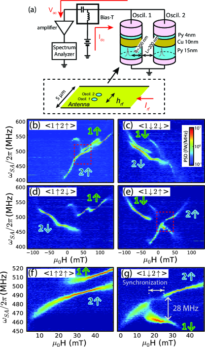
Our sample consists of two cylindrical spin-torque nano-oscillators with identical nominal diameters of nm and an edge-to-edge separation of nm, as shown in Fig. 1(a). Each oscillator has a spin-valve layer structure of Py(15 nm)/Cu(10 nm)/Py(4 nm) (Py = Ni80Fe20). During operation a strong dc current is injected through the two oscillators in parallel, which favors a vortex state in all Py layers sup . It flows from Py(4 nm) to Py(15 nm), so that in each oscillator the spin-transfer torque destabilizes the mode dominated by the thick layer and overdamps the thin layer dynamics Khvalkovskiy et al. (2010); Locatelli et al. (2011); Hamadeh et al. (2014b). The current is set to 95 mA, i.e., 1.5 times as the critical current to drive the auto-oscillations of the thick Py layers. The dynamics excited in each oscillator corresponds to the rotation of the vortex core around its equilibrium position, the so-called gyrotropic mode Guslienko et al. (2002). Because of the small lateral separation, the two oscillators are dynamically coupled through their dipolar field Belanovsky et al. (2012); Locatelli et al. (2015). We note that owing to their much smaller volumes and limited dynamics, the contribution of the thin layer vortices to the oscillator-oscillator coupling is weak. Moreover, their vortex core polarity is not purposely controlled in this study. In the following, we will thus refer exclusively to the vortices in the thick Py layers of each oscillator, labeled 1 and 2. To provide an external rf field, an electrically isolated antenna is patterned on top of the sample Naletov et al. (2011), creating an in-plane linearly polarized along the direction made by the two oscillators (see Fig. 1a). Furthermore a biasing magnetic field is applied perpendicular to the sample plane in order to vary the gyrotropic frequencies de Loubens et al. (2009); Dussaux et al. (2012).
First we examine the microwave signals associated with auto-oscillations in each oscillator. Figs. 1(b-e) show the color maps of the power spectral density as a function of perpendicular field . In each graph, two branches corresponding to the gyrotropic modes of the thick layer vortex in each oscillator are observed. The four combined vortex polarity states for oscillators 1 and 2 can be obtained after applying well-chosen perpendicular switching fields Locatelli et al. (2011). The polarity state of oscillator is defined as () for vortex core magnetization parallel (antiparallel) to the positive biasing field direction, which corresponds to a positive (negative) frequency-field slope de Loubens et al. (2009); Dussaux et al. (2012).
Next we demonstrate the existence of dipolar coupling by the observation of mutual synchronization. Figs. 1(f,g) compare the zoomed-in power spectra of and states for mT, as labeled by the red boxes in Figs. 1(b) and (e), respectively. By switching the polarity of vortex oscillator 1, a clear gap of the auto-oscillation branch for oscillator 2 is found between and 26 mT in state, while for state the branch is continuous. This gap, accompanied by a bright lower-frequency branch, is associated to the synchronization of the two oscillators. From the right edge of the synchronization bandwidth we deduce that the maximal frequency mismatch for mutual synchronization is 28 MHz. The frequency mismatch corresponding to the unlocking of the two oscillators at the left edge is smaller. We attribute this to the fact that the amplitude and linewidth of oscillators can vary with the perpendicular field Hamadeh et al. (2014b), which will change the effective dipolar coupling. The results above show that the dipolar interaction is strong enough to synchronize the two oscillators. Still, a quantitative evaluation of its strength and phase shift is lacking at this point of the analysis.
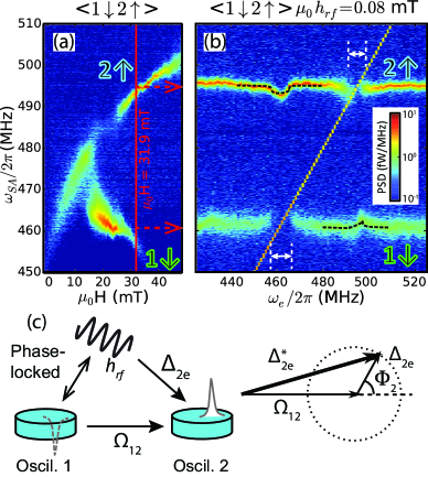
In order to directly reveal and quantify the dipolar coupling, we fix both the biasing current and magnetic field and apply a weak microwave field, which couples to both oscillators. The two oscillators are set to an unsynchronized state at mT, shown in Fig. 2(a). Fig. 2(b) shows the evolution of auto-oscillation peaks of the two oscillators as a function of the external microwave field frequency . When crosses the peak of oscillator 1 around 460 MHz, the disappearance of the peak reflects the phase locking to the external rf source Rippard et al. (2005); Georges et al. (2008); Hamadeh et al. (2014a). In addition, we also detect a significant frequency pulling on oscillator 2. This is a striking observation, because the frequency mismatch between oscillators, MHz, is five times larger than the phase-locking bandwidths, around 7 MHz, of the two oscillators to the external source. The remote frequency pulling is a strong indication of coupling between the two oscillators as it is bound to the phase-locking bandwidth. It is important to note that no obvious frequency shift is observed when lies between the two auto-oscillation peaks. Reciprocally, a similar effect is also observed on oscillator 1 when oscillator 2 is phase-locked to the microwave field around 495 MHz.
To understand these phenomena, we develop a simplified analytical formalism based on general oscillator equations Slavin and Tiberkevich (2009). For two dipolarly coupled vortex oscillators experiencing a linearly polarized microwave field, the phase equations can be formulated sup from the Thiele equation which describes the vortex core dynamics in a magnetic dot Guslienko (2006); Ivanov and Zaspel (2007); Khvalkovskiy et al. (2009), as:
| (2) |
where is the phase difference between the microwave field and the position of the vortex core, is the vortex polarity, is the free-running frequency of oscillator , is the dipolar coupling strength normalized by the ratio of vortex gyration amplitudes and is the coupling strength to the external microwave source. The index is defined as or . In Eq. (2) two additional phases are present: is the intrinsic phase shift introduced by the nonlinearity of the oscillators Slavin and Tiberkevich (2009); Tiberkevich et al. (2009); is the microwave coupling phase, determined by the geometric alignment of the microwave field to each oscillator (see Fig. 1(a)). We highlight that Eq. (2) describes the general behaviors of self-sustained oscillators: for , it is reduced to Kuramoto equations Eq. (1) with , where the phase originates from the conservative nature of dipolar coupling Slavin and Tiberkevich (2009); for , it is reduced to the Adler equation responsible for one oscillator phase-locking to an external source Adler (1973).
In the general case, the phase dynamics of oscillator 2 evolves in a complex way due to the uncorrelated forces exerted by the microwave field and oscillator 1. However, when oscillator 1 phase-locks to the microwave field, the situation simplifies: its relative phase with respect to the microwave field, , becomes a constant. In that case, we can rewrite the phase dynamics of oscillator 2 in Eq. (2) as driven solely by the action of the microwave field, but with a modified effective coupling strength that takes into account both the microwave couplings, and the dipolar attraction to oscillator 1:
| (3) |
From Eq. (3), we find is the vector sum of the effective dipolar coupling strength and the microwave coupling strength with a phase difference (Fig. 2c). The frequency of oscillator 2 is then determined by the frequency of the microwave field, and the strength of this new effective coupling through:
| (4) |
where “” depends on the sign of . Eq. (4) indicates that when oscillator 1 is phase locked to the microwave field, it can help pulling the frequency of oscillator 2 towards the frequency of the source, as observed in Fig. 2(b).
| antiparallel | parallel | ||||
|---|---|---|---|---|---|
| (mT) | 0.05 | 0.08 | 0.14 | 0.05 | 0.08 |
| (MHz) | 1.8 | 3.2 | 5.5 | 1.8 | 3.5 |
| (MHz) | -6.7 | -7.9 | -9.3 | 3.6 | 4.2 |
| (rad) | -2.7 | -2.8 | -2.0 | 2.6 | 2.1 |
| (rad) | 1.1 | 1.1 | 0.7 | -2.1 | -1.4 |
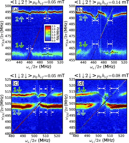
Full analytical solutions to our model can be obtained in the limit of weak microwave coupling sup . In Fig. 3 we use them to extract the coupling parameters under different conditions. First, the microwave power is varied, which sets the phase-locking bandwidths and associated remote frequency pullings. Second, both antiparallel (Figs. 3a,b) and parallel (Figs. 3c,d) vortex polarity alignments are examined, for which the strength of dipolar coupling is expected to change by a factor close to three Abreu Araujo et al. (2015); Locatelli et al. (2015). The data are fitted to Eq. (4) with and as the fit parameters. Positive and negative signs of are expected for parallel and antiparallel polarity alignments, respectively Abreu Araujo et al. (2015), which is taken into account. Details about the fitting procedure can be found in the Supplemental Information sup . The fitting curves are shown in Fig. 3 and Fig. 2(b).
Table I lists the fitting results along with the microwave field amplitude . As expected the mean of phase-locking strengths is proportional to the microwave field. For the antiparallel polarity alignment, the extracted dipolar coupling slightly increases with . One reason is that the vortex gyration amplitude might be increased as oscillator is phase-locked to the microwave field, resulting in an enhancement of on oscillator . Another possibility is the incomplete phase locking at small (observed in Fig. 3a for oscillator 2) due to thermal fluctuations, which are likely to reduce the effective coupling Georges et al. (2008); Hamadeh et al. (2014a). Owing to these two counteracting effects, we take the average of the three experiments, MHz, as the extracted value of . For the parallel polarity state, we take the value extracted from Fig. 3(c), MHz, as the strength of the dipolar coupling. In fact, the limit of weak microwave coupling does not hold in Fig. 3(d) due to the large microwave power in comparison to the small frequency mismatch between oscillators, which results in a more complex dynamics. It is interesting to note that the two values compare favorably with the ones obtained from macrodipole approximation taking into account solely the thick Py layers Belanovsky et al. (2012); Abreu Araujo et al. (2015). In that case MHz, where from the two-vortex ansatz Guslienko et al. (2002), GHz/T is the gyromagnetic ratio, T the saturation magnetization of the Py vortex layers Naletov et al. (2011), their thickness, and the center-to-center distance between oscillators. We also point out that the ratio in our experiment agrees with the ratio of critical frequency mismatch, in our prior work Locatelli et al. (2015), and depends on the exact geometry of the oscillator pair Abreu Araujo et al. (2015).
The phase shift is linked to the position of the largest remote frequency pulling in Fig. 3. In the antiparallel polarity alignment the values of are reproducible at various microwave fields but differ from that in the parallel alignment, indicating large variations of parameters in magnetic dynamics upon polarity change. From the model, is the reduced nonlinear coefficient of oscillator Slavin and Tiberkevich (2009). However we note that the fitting results with negative values of point towards either additional extrinsic phase due, e.g., to parasitic rf couplings between the antenna and sample circuits, or more complex dynamics than assumed in the simple analytical model.
One interesting finding is that the extracted in the antiparallel polarity alignment is much smaller than the phase-locking frequency mismatch of 28 MHz found in Fig. 1(g). In our experiments the amplitude ratio is close to one sup . In the phase-locking solution derived by Slavin and Tiberkevich Slavin and Tiberkevich (2006), the maximal frequency mismatch for mutual synchronization is then . Thus we confirm the role of nonlinearities, with around 3.5, in the large phase-locking frequency mismatch. The fact that the synchronized mode is closer to the peak branch of oscillator 1 likely indicates that is greater than , making it easier for oscillator 2 to adapt its frequency to oscillator 1.
Our results show that two dipolarly coupled spin-torque vortex oscillators follow ideal oscillator systems described by Eq. (2), a pre-assumption for studies based on the Kuramoto model Flovik et al. (2016). We confirm that the dipolar coupling strength can be tuned by a factor greater than two with bistable polarity states Abreu Araujo et al. (2015); Locatelli et al. (2015), providing a unique freedom to manipulate the collective dynamics. For instance, a new propagating wave mode has been predicted in oscillator arrays with both attracting and repulsive interactions Hong and Strogatz (2011), which can be realized with the two different polarity alignments. In addition we learn about the nonlinearities in spin-torque nano-oscillators. Finite phase shifts are measured, as predicted in theory Zhou et al. (2007); Slavin and Tiberkevich (2009) and identified in similar systems Lebrun et al. (2015, 2016). This indicates that practical oscillator networks fall into the Sakaguchi-Kuramoto regime (Eq. 1 with nonzero ), in which synchronization can be destroyed by the phase detunings at medium Omel’chenko and Wolfrum (2012).
In summary, we have developed a novel approach to study coupled oscillators with an external ac drive. By controlling the relative phases between the ac source and one phase-locked oscillator, we acquire not only the strength but also the phase information of the inter-oscillator coupling. This probing technique is not restricted to spin-torque oscillators and microwave field, but applicable to all coupled oscillator systems and ac drives. By extending their understanding, it is also useful for further manipulation and investigation of collective dynamics in large arrays of auto-oscillators.
We thank R. Lebrun, V. V. Naletov and A. N. Slavin for fruitful discussions. We acknowledge the MEMOS project ANR-14-CE26-0021 for financial support.
References
- Pikovsky et al. (2001) A. Pikovsky, M. Rosenblum, and J. Kurths, Synchronization: A universal concept in nonlinear sciences (Cambridge University Press, Cambridge, UK, 2001).
- Wiesenfeld et al. (1996) K. Wiesenfeld, P. Colet, and S. H. Strogatz, Phys. Rev. Lett. 76, 404 (1996).
- Shim et al. (2007) S.-B. Shim, M. Imboden, and P. Mohanty, Science 316, 95 (2007).
- Heinrich et al. (2011) G. Heinrich, M. Ludwig, J. Qian, B. Kubala, and F. Marquardt, Phys. Rev. Lett. 107, 043603 (2011).
- Zhang et al. (2012) M. Zhang, G. S. Wiederhecker, S. Manipatruni, A. Barnard, P. McEuen, and M. Lipson, Phys. Rev. Lett. 109, 233906 (2012).
- Kaka et al. (2005) S. Kaka, M. R. Pufall, W. H. Rippard, T. J. Silva, S. E. Russek, and J. A. Katine, Nature 437, 389 (2005).
- Mancoff et al. (2005) F. B. Mancoff, N. D. Rizzo, B. N. Engel, and S. Tehrani, Nature 437, 393 (2005).
- Kiss et al. (2002) I. Z. Kiss, Y. Zhai, and J. L. Hudson, Science 296, 1676 (2002).
- Tinsley et al. (2012) M. R. Tinsley, S. Nkomo, and K. Showalter, Nat. Phys. 8, 662 (2012).
- Hartwell et al. (1999) L. H. Hartwell, J. J. Hopfield, S. Leibler, and A. W. Murray, Nature 402, C47 (1999).
- Locatelli et al. (2013) N. Locatelli, V. Cros, and J. Grollier, Nat. Mater. 13, 11 (2013).
- Grollier et al. (2016) J. Grollier, D. Querlioz, and M. D. Stiles, Proc. IEEE 104, 2024 (2016).
- Kuramoto (1984) Y. Kuramoto, Chemical Oscillations, Waves, and Turbulence (Springer, Berlin, 1984).
- Acebrón et al. (2005) J. A. Acebrón, L. L. Bonilla, C. J. Pérez-Vicente, F. Ritort, and R. Spigler, Rev. Mod. Phys. 77, 137 (2005).
- Slavin and Tiberkevich (2009) A. Slavin and V. Tiberkevich, IEEE Trans. Magn. 45, 1875 (2009).
- Ruotolo et al. (2009) A. Ruotolo, V. Cros, B. Georges, A. Dussaux, J. Grollier, C. Deranlot, R. Guillemet, K. Bouzehouane, S. Fusil, and A. Fert, Nature Nano. 4, 528 (2009).
- Sani et al. (2013) S. Sani, J. Persson, S. M. Mohseni, Y. Pogoryelov, P. K. Muduli, A. Eklund, G. Malm, M. Käll, A. Dmitriev, and J. Åkerman, Nature Comm. 4, 2731 (2013).
- Locatelli et al. (2015) N. Locatelli, A. Hamadeh, F. Abreu Araujo, A. D. Belanovsky, P. N. Skirdkov, R. Lebrun, V. V. Naletov, K. A. Zvezdin, M. Muñoz, J. Grollier, O. Klein, V. Cros, and G. de Loubens, Sci. Rep. 5, 17039 (2015).
- Lebrun et al. (2016) R. Lebrun, S. Tsunegi, P. Bortolotti, H. Kubota, A. S. Jenkins, M. Romera, K. Yakushiji, A. Fukushima, J. Grollier, S. Yuasa, and V. Cros, arXiv , 1601.01247 (2016).
- Tiberkevich et al. (2009) V. Tiberkevich, A. Slavin, E. Bankowski, and G. Gerhart, Appl. Phys. Lett. 95, 262505 (2009).
- Omel’chenko and Wolfrum (2012) O. E. Omel’chenko and M. Wolfrum, Phys. Rev. Lett. 109, 164101 (2012).
- Csaba et al. (2012) G. Csaba, M. Pufall, D. Nikonov, G. Bourianoff, A. Horvath, T. Roska, and W. Porod, in Cellular Nanoscale Networks and Their Applications (CNNA), 2012 13th International Workshop on (2012) pp. 1–2.
- Nikonov et al. (2015) D. E. Nikonov, G. Csaba, W. Porod, T. Shibata, D. Voils, D. Hammerstrom, I. A. Young, and G. I. Bourianoff, IEEE Journal on Exploratory Solid-State Computational Devices and Circuits 1, 85 (2015).
- Kiselev et al. (2003) S. I. Kiselev, J. C. Sankey, I. N. Krivorotov, N. C. Emley, R. J. Schoelkopf, R. A. Buhrman, and D. C. Ralph, Nature 425, 380 (2003).
- Rippard et al. (2005) W. H. Rippard, M. R. Pufall, S. Kaka, T. J. Silva, S. E. Russek, and J. A. Katine, Phys. Rev. Lett. 95, 067203 (2005).
- Georges et al. (2008) B. Georges, J. Grollier, M. Darques, V. Cros, C. Deranlot, B. Marcilhac, G. Faini, and A. Fert, Phys. Rev. Lett. 101, 017201 (2008).
- Urazhdin et al. (2010) S. Urazhdin, P. Tabor, V. Tiberkevich, and A. Slavin, Phys. Rev. Lett. 105, 104101 (2010).
- Quinsat et al. (2011) M. Quinsat, J. F. Sierra, I. Firastrau, V. Tiberkevich, A. Slavin, D. Gusakova, L. D. Buda-Prejbeanu, M. Zarudniev, J.-P. Michel, U. Ebels, B. Dieny, M.-C. Cyrille, J. A. Katine, D. Mauri, and A. Zeltser, Appl. Phys. Lett. 98, 182503 (2011).
- Hamadeh et al. (2014a) A. Hamadeh, N. Locatelli, V. V. Naletov, R. Lebrun, G. de Loubens, J. Grollier, O. Klein, and V. Cros, Appl. Phys. Lett. 104, 022408 (2014a).
- Lebrun et al. (2015) R. Lebrun, A. Jenkins, A. Dussaux, N. Locatelli, S. Tsunegi, E. Grimaldi, H. Kubota, P. Bortolotti, K. Yakushiji, J. Grollier, A. Fukushima, S. Yuasa, and V. Cros, Phys. Rev. Lett. 115, 017201 (2015).
- Pribiag et al. (2007) V. S. Pribiag, I. N. Krivorotov, G. D. Fuchs, P. M. Braganca, O. Ozatay, J. C. Sankey, D. C. Ralph, and R. A. Buhrman, Nature Phys. 3, 498 (2007).
- Dussaux et al. (2010) A. Dussaux, B. Georges, J. Grollier, V. Cros, A. V. Khvalkovskiy, A. Fukushima, M. Konoto, H. Kubota, K. Yakushiji, S. Yuasa, K. A. Zvezdin, K. Ando, and A. Fert, Nature Commun. 1, 8 (2010).
- Locatelli et al. (2011) N. Locatelli, V. V. Naletov, J. Grollier, G. de Loubens, V. Cros, C. Deranlot, C. Ulysse, G. Faini, O. Klein, and A. Fert, Appl. Phys. Lett. 98, 062501 (2011).
- Hamadeh et al. (2014b) A. Hamadeh, N. Locatelli, V. V. Naletov, R. Lebrun, G. de Loubens, J. Grollier, O. Klein, and V. Cros, Phys. Rev. Lett. 112, 257201 (2014b).
- Sluka et al. (2015) V. Sluka, A. Kákay, A. M. Deac, D. E. Bürgler, C. M. Schneider, and R. Hertel, Nat. Comm. 6, 6409 (2015).
- de Loubens et al. (2009) G. de Loubens, A. Riegler, B. Pigeau, F. Lochner, F. Boust, K. Y. Guslienko, H. Hurdequint, L. W. Molenkamp, G. Schmidt, A. N. Slavin, V. S. Tiberkevich, N. Vukadinovic, and O. Klein, Phys. Rev. Lett. 102, 177602 (2009).
- Shibata et al. (2003) J. Shibata, K. Shigeto, and Y. Otani, Phys. Rev. B 67, 224404 (2003).
- Sugimoto et al. (2011) S. Sugimoto, Y. Fukuma, S. Kasai, T. Kimura, A. Barman, and Y. C. Otani, Phys. Rev. Lett. 106, 197203 (2011).
- Han et al. (2013) D.-S. Han, A. Vogel, H. Jung, K.-S. Lee, M. Weigand, H. Stoll, G. Schütz, P. Fischer, G. Meier, and S.-K. Kim, Sci. Rep. 3, 2262 (2013).
- Belanovsky et al. (2012) A. D. Belanovsky, N. Locatelli, P. N. Skirdkov, F. Abreu Araujo, J. Grollier, K. A. Zvezdin, V. Cros, and A. K. Zvezdin, Phys. Rev. B 85, 100409(R) (2012).
- Belanovsky et al. (2013) A. D. Belanovsky, N. Locatelli, P. N. Skirdkov, F. Abreu Araujo, K. A. Zvezdin, J. Grollier, V. Cros, and A. K. Zvezdin, Appl. Phys. Lett. 103, 122405 (2013).
- Abreu Araujo and Grollier (2016) F. Abreu Araujo and J. Grollier, J. Appl. Phys. 120, 103903 (2016).
- Abreu Araujo et al. (2015) F. Abreu Araujo, A. D. Belanovsky, P. N. Skirdkov, K. A. Zvezdin, A. K. Zvezdin, N. Locatelli, R. Lebrun, J. Grollier, V. Cros, G. de Loubens, and O. Klein, Phys. Rev. B 92, 045419 (2015).
- Dussaux et al. (2012) A. Dussaux, A. V. Khvalkovskiy, P. Bortolotti, J. Grollier, V. Cros, and A. Fert, Phys. Rev. B 86, 014402 (2012).
- Flovik et al. (2016) V. Flovik, F. Macià, and E. Wahlström, Sci. Rep. 6, 32528 (2016).
- (46) See the Supplemental Information for details.
- Khvalkovskiy et al. (2010) A. V. Khvalkovskiy, J. Grollier, N. Locatelli, Y. V. Gorbunov, K. A. Zvezdin, and V. Cros, Appl. Phys. Lett. 96, 212507 (2010).
- Guslienko et al. (2002) K. Y. Guslienko, B. A. Ivanov, V. Novosad, Y. Otani, H. Shima, and K. Fukamichi, J. Appl. Phys. 91, 8037 (2002).
- Naletov et al. (2011) V. V. Naletov, G. de Loubens, G. Albuquerque, S. Borlenghi, V. Cros, G. Faini, J. Grollier, H. Hurdequint, N. Locatelli, B. Pigeau, A. N. Slavin, V. S. Tiberkevich, C. Ulysse, T. Valet, and O. Klein, Phys. Rev. B 84, 224423 (2011).
- Guslienko (2006) K. Y. Guslienko, Appl. Phys. Lett. 89, 022510 (2006).
- Ivanov and Zaspel (2007) B. A. Ivanov and C. E. Zaspel, Phys. Rev. Lett. 99, 247208 (2007).
- Khvalkovskiy et al. (2009) A. V. Khvalkovskiy, J. Grollier, A. Dussaux, K. A. Zvezdin, and V. Cros, Phys. Rev. B 80, 140401(R) (2009).
- Adler (1973) R. Adler, Proc. IRE 34, 351 (1973).
- Slavin and Tiberkevich (2006) A. N. Slavin and V. S. Tiberkevich, Phys. Rev. B 74, 104401 (2006).
- Hong and Strogatz (2011) H. Hong and S. H. Strogatz, Phys. Rev. Lett. 106, 054102 (2011).
- Zhou et al. (2007) Y. Zhou, J. Persson, and J. Åkerman, J. Appl. Phys. 101, 09A510 (2007).