DEVELOPMENTS FOR THE ISODAR@KAMLAND AND DAEALUS DECAY-AT-REST NEUTRINO EXPERIMENTS
Abstract
Configurations of the IsoDAR and DAEALUS decay-at-rest neutrino experiments are described. Injector and cyclotron developments aimed at substantial increases in beam current are discussed. The IsoDAR layout and target are described, and this experiment is compared to other programs searching for sterile neutrinos.
1 Introduction
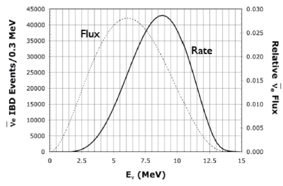
Decay-At-Rest (DAR) experiments offer attractive features for neutrino physics studies.[1] We discuss two particular regimes where the characteristics of the source are determined by the nature of the weak-interaction decay producing the neutrino, and are not affected by kinematics or characteristics of higher-energy production mechanisms. The beta decay case is manifested in the IsoDAR experiment; a sterile-neutrino search where a 60 MeV proton beam is used to produce the parent isotope, 8Li. The product nucleus is stationary when it decays, the neutrino spectrum is shown in Figure 1. It has a high endpoint energy, over 13 MeV, and a mean energy of 6.5 MeV, both substantially higher than backgrounds from other decays, and in an area easily accessible for detection by Inverse Beta Decay (IBD) in a hydrogen-containing neutrino detector.

In the regime where pions are produced at low energy (with MeV protons), pions can stop in the target before decaying. This is the case for DAEALUS, a sensitive CP violation measurement. As the nuclear capture probability for at rest in the target is extremely high, the neutrino spectrum from the stopped pions will be dominated by the decay of by a factor of about . Figure 2 shows the neutrino spectra from the decay. Noteworthy in this decay is the absence of electron antineutrinos, making this source a favored means of looking for appearance of , again utilizing IBD in a suitable neutrino detector.
These neutrino sources are isotropic, there is no kinematic directionality to define a beam. As a result, the efficiency of detection is directly related to the solid angle subtended by the detector, placing high emphasis on having the source as close to the detector as possible. In the case of IsoDAR this distance is a few meters from the detector surface (16.5 meters from the center of the KamLAND fiducial volume), in the case of DAEALUS the baseline is 20 km from the large water-Cherenkov counter (assumed to be Hyper-K). As the principal goals of these experiments is oscillation physics, the driving term is L/E, the baseline distance divided by the neutrino energy. If E is low, the baseline L can also be low to preserve the same ratio. As a consequence, the 20 km baseline and 45 MeV average energy addresses the same oscillation point as the 1300 km, 3 GeV DUNE beam, or the 300 km, 500 MeV T2K beam.
The premise of these experiments is that relatively small and compact sources of neutrinos can be built and installed at the proper distances from existing or planned large water- or liquid-scintillator-based neutrino detectors, providing access to the physics measurements with substantially reduced costs. With respect to the long-baseline experiments (e.g. T2K) the beamlines from the major accelerator centers operate much more efficiently and cleanly in the neutrino mode, while the DAR measurements, utilizing IBD, address only the anti-neutrino mode. Consequently, installing DAEALUS cyclotrons at the proper distance from the long-baseline detectors, and operating the neutrino beams simultaneously, offers a huge improvement in the sensitivity and data rates over the individual experiments. Discrimination of the source of events is straightforward, both from the energy deposition of events from each source, as well as from timing: neutrinos from the cyclotrons are essentially continuous (up to 100 duty factor), while those from the large accelerators are tightly pulsed with a very low overall duty factor.
Nevertheless, the lack of directionality of DAR neutrinos, and the small solid angle between source and detector calls for the highest-possible flux from the source to ensure meaningful data rates. Available accelerator technologies and design configurations have been explored, for beam current performance, cost and footprint; we have arrived at the choice of compact cyclotrons [2]. The only deficiency of this option is the average current. For appropriate data rates, our specification is 10 mA of protons on target. This pushes the highest current from cyclotrons by about a factor of 3,111Isotope-producing cyclotrons rarely reach 2 mA, the current record-holder for cyclotron current is the 3 mA PSI Injector 2, a 72 MeV separated-sector proton cyclotron injecting the 590 MeV Ring Cyclotron. and much of the accelerator development work of our group to date has been devoted to addressing the factors that limit the maximum current in compact cyclotrons [3][4][5].

In the next section the physics rationale for the IsoDAR and DAEALUS experiments will be briefly described, while subsequent sections will address the configuration of the cyclotrons, and progress made in pushing the current limits from cyclotrons to the required level. The IsoDAR target will be described, capable of handling the 600 kW of proton beams and optimized for 8Li production. Finally, the IsoDAR experiment will be compared with other ongoing initiatives for searching for sterile neutrinos.
2 Neutrino Measurements
2.1 IsoDAR
Anomalies in disappearance rates have been observed in reactor and radioactive source experiments [6]. Postulated to explain these has been the existence of one or more sterile neutrinos, that do not in themselves interact in the same manner as “active” neutrinos (hence are called “sterile”), however the active neutrinos can oscillate through these sterile states, and in this manner affect the ratio of appearance and disappearance from the known three flavor eigenstates. Global fits [7] of data from experiments point to a mass splitting in the order of 1 to almost 8 eV 2, and a sin2(2 ) of 0.1. Recent analysis of IceCube data [8], exploiting a predicted resonance in the MSW matrix for passing through the core of the earth appear to rule out m2 values of 1 eV 2 or below, however values above this energy are still possible.
The very large m2 imply a very short wavelength for the oscillations, in fact for the 8Li neutrino it is measured in meters, so within the fiducial volume of KamLAND one could see several full oscillations. Folding in the spatial and energy resolutions of the KamLAND detector (12 cm/) and (6.4%/) respectively, the expected neutrino interaction pattern for the case of m2 = 1.75 eV 2 is shown in Figure 3.
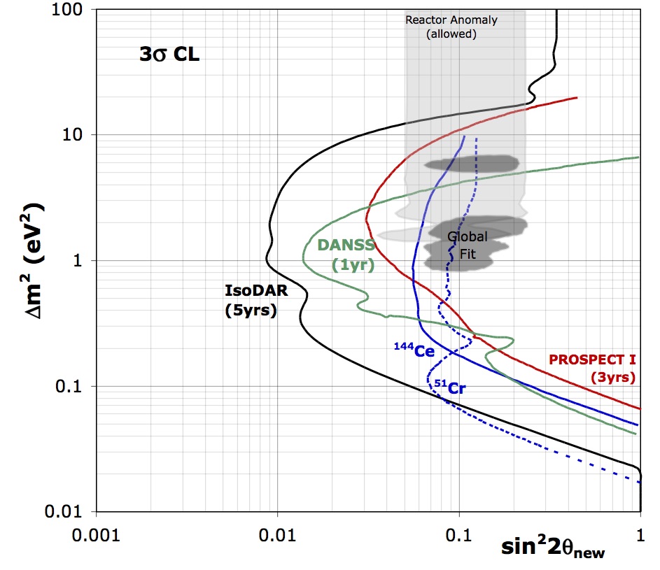
Figure 4 shows a sensitivity plot for IsoDAR, this experiment covers very well the regions of interest for sterile neutrinos.
2.2 Layout of DAEALUS Experiment
Search for CP violation in the lepton sector has been a high priority for many years. DAEALUS combined with a long-baseline beam (e.g. T2K @ Hyper-K operating in neutrino mode only) can in 10 years cover almost all of the CP-violating phase angles.[12]

The experimental configuration includes three stations, each with identical targets that provide neutrino sources (from stopped ), one at 1.5 km (essentially as close to the detector as feasible) that normalizes the flux seen in the detector, one at 8 km that catches the rise in the appearance, and the principal station at 20 km, which measures the appearance at the peak of the oscillation curve. The absolute appearance amplitude is modulated by the CP-violating phase. The current on target, hence the neutrino flux, is adjusted sequentially at each station (by “beam-on” timing) to be approximately equivalent to the flux from the long-baseline beam. The total timing cycle from all stations allows approximately 40% of time when none are delivering neutrinos, for background measurements.
3 Cyclotron Configuration
Figure 5 shows schematically the basic configuration of a cyclotron “module” for DAEALUS, showing the “chain” of injector-booster cyclotron with a top energy of 60 MeV, and the main DAEALUS superconducting ring cyclotron (DSRC) which delivers 800 MeV protons to the pion-production target. Note that the injector cyclotron is exactly the machine that is needed for the IsoDAR experiment, so developing this cyclotron is a direct step in the path towards DAEALUS.
| IsoDAR | DAEALUS | |
| Particle accelerated | ||
| Maximum energy | 60 MeV/amu | 800 MeV/amu |
| Extraction | Septum | Stripping |
| Peak beam current () | 5 mA | 5 mA |
| Peak beam current (proton) | 10 mA | 10 mA |
| Number of stations | 1 | 3 |
| Duty factor | 100% | 15% - 50% (time switching between 3 stations) |
| Peak beam power on target | 600 kW | 8 MW |
| Peak power density on target | 2 kW/cm2 | 2 kW/cm2 |
| Average beam power on target | 600 kW | 1.2 to 4 MW |
| Maximum steel diameter | 6.2 meters | 14.5 meters |
| Approximate weight | 450 tons | 5000 tons |
Table 1 lists high-level parameters for the IsoDAR and DAEALUS cyclotrons. Note the power implication of delivering 10 mA to the production targets. These very high power-requirements call for minimizing beam loss during the acceleration and transport process. Any beam loss is not only destructive of components, but also activates materials and greatly complicates maintenance of accelerator systems. Some beam loss is unavoidable, however by appropriate use of cooled collimators and beam dumps, and by restricting as much as possible these losses to the lower energy regions of the cyclotrons, the thermal and activation damage can be minimized.
The single biggest innovation in these cyclotrons, aimed at increasing the maximum current, is the use of ions [13] instead of protons or . As the biggest source of beam loss is space charge blowup at low energies, the lower q/A (2 protons for a single charge), and higher mass per ion (= 2 amu - atomic mass units) greatly reduces the effects of the repulsive forces of the very high charge in a single bunch of accelerated beam. This helps keep the size of the accelerated bunches down so there will be less beam lost on the inside of the cyclotron. Keeping the molecular ion to the full energy also allows for stripping extraction at 800 MeV/amu, reducing beam loss in the extraction channels.
While the size and weight of these cyclotrons may appear large, there are examples of machines of comparable size that can serve as engineering models for beam dynamics, magnetic field design and costing. The PSI Injector 2, a 72-MeV 3-mA machine models some aspects of the IsoDAR cyclotron relating to the RF system and space-charge dominated beam dynamics [14]. Magnet design and steel size/weight bear some similarities to IBA’s 235 MeV proton radiotherapy cyclotron [15]. The DSRC bears significant similarities to the superconducting ring cyclotron at RIKEN [16]. While this cyclotron is designed for uranium beams, so the beam dynamics are not directly relevant, the cryostat and magnet designs are extremely close to the DAEALUS requirements, and so serve as a good engineering and costing model for the DSRC.
4 IsoDAR developments
As indicated above, efforts of our group have focused on producing high currents of for injection into the IsoDAR cyclotron, modeling the capture and acceleration of these ions, and on the design of the target for handling 600 kW of proton beam and maximizing the production of 8Li to generate the flux delivered to KamLAND.
4.1 Producing High Currents of H for Injection
Experiments at the Best Cyclotron Systems, Inc. test stand in Vancouver, BC [3] tested the VIS high-current proton source [17] for its performance in generating beams. Our requirement for is a maximum of 50 mA of continuous beam from the source, which would provide an adequate cushion in the event that capture into the cyclotron cannot be enhanced by efficient time-bunching of the beam (see next section). The VIS only produced about 15 mA of (while we did measure 40 mA of protons); using this source would require efficient bunching. To increase our safety margin, a new ion source, labeled “MIST-1” has been built [18] based on an LBL-developed filament-driven, multicusp design [19] which demonstrated a much more favorable p/ ratio, and currents in the range required. This source has been designed with a high degree of flexibility, to adjust geometric, magnetic field and plasma conditions to optimize performance. It is now being commissioned.
4.2 Capturing and Accelerating High Currents of H
Cyclotrons accelerate beam via RF (radio-frequency, for our cyclotron around 50 MHz) fields applied to electrodes (called “Dees”) extending along the full radial extent of the beam. Particles reaching the accelerating gap at the right phase of the RF will receive a positive kick, while those arriving outside this phase angle will be decelerated and lost. The phase acceptance of the cyclotron is typically about , so if the injected beam is not bunched longitudinally, only 10% of a continuous beam will be accepted. Hence the need for 50 mA of unbunched beam. Bunching is conventionally done with a double-gap RF cavity placed about one meter ahead of the injection point. Maximum efficiency improvement is no more than a factor of 2 or 3.
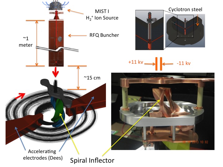
A novel bunching technique using an RFQ was proposed many years ago [20] that could in principle improve bunching efficiency to almost 85%. We have recently been awarded funding from NSF to develop this technique, and are working with the original proponent, and other key RFQ groups in the US and Europe to build and test this new buncher. Figure 6 shows schematically the central region of the cyclotron, including the MIST-1 source, the RFQ, and spiral inflector that bunches and bends the beam into the plane of the cyclotron.
Once inflected into the plane of the cyclotron, the beam must be stably captured and accelerated to the full energy and extraction radius (of 2 meters in our case). In addition, there must be adequate turn separation at the outer radius to cleanly extract the beam. The particles experience 96 turns from injection to extraction, and the radial size of the beam must be controlled so that a thin septum can be inserted between the 95th and 96th turns that will not intercept any appreciable amount of beam. With a total of 600 kW, even a fraction of a percent of beam lost on this septum can damage it.
Extensive simulations, using the OPAL code [21] developed at PSI specifically for beam-dynamics of highly space-charge-dominated beams in cyclotrons have been used to show that this is possible, and to locate collimators and scrapers in the first few turns to control beam halo (that would be intercepted on the extraction septum). This code has also shown that space-charge forces can actually contribute to stability of the accelerating bunch by introducing a vortex motion within the bunch that limits longitudinal and transverse growth of the bunch [22].
These developments give us confidence that the technical specifications for the IsoDAR cyclotron can be met.
4.3 Target design
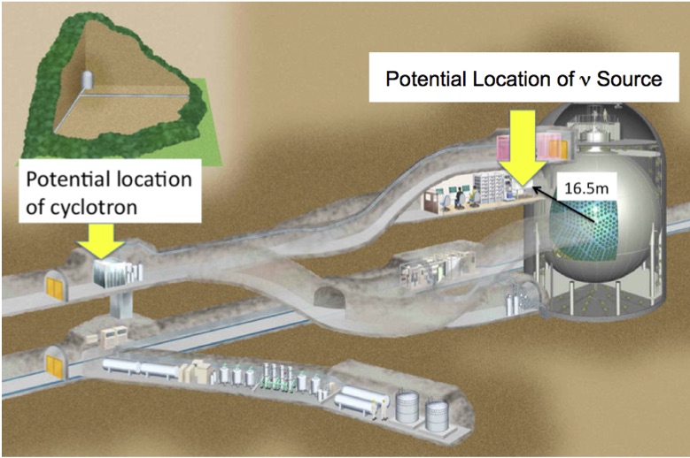
The configuration of the IsoDAR experiment is shown in Fig 7. The cyclotron is located in a vault previously used for water purification, the target is located in one of the construction drifts repurposed as a control room that is no longer used.

Beam is extracted from the cyclotron and transported about 50 meters to the target located close to the KamLAND detector. The 5 mA of is stripped in this transport line, the resulting 10 mA of protons are directed to the beryllium target. Beryllium is a very efficient neutron producer, for the 60 MeV proton beam the yield is approximately 1 neutron per 10 protons. These neutrons stream through to the sleeve surrounding the target, containing small beryllium spheres (less than 1 cm diameter) surrounded by highly-enriched 7Li (99.995%) . The sleeve is a cylinder 50 cm in radius and 2 meters long, and is surrounded by a 5 cm graphite reflector. Shielding outside the reflector consisting of iron and borated concrete which contains the neutron flux to limit neutrons reaching the rock walls.
Fig 8 shows the target, sleeve and shielding assembly in relation to the KamLAND detector. The 8Li yield from the moderated and captured neutrons varies with the fractional composition of beryllium and lithium in the sleeve, the maximum is about 3% (8Li per incident proton on target) for 30% (by weight) of lithium. This is close to the interstitial volume of tightly packed spheres. All numbers are based on GEANT4 calculations [23].
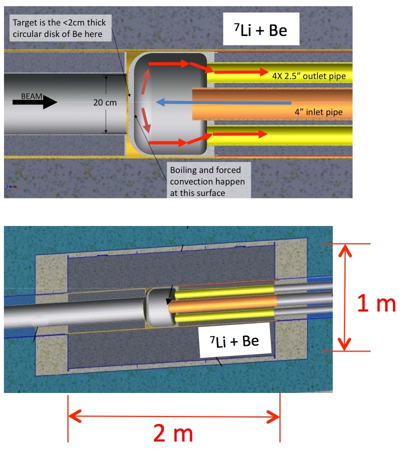
Fig 9 shows the target assembly, a spun-cast beryllium piece with the front surface (where the beam hits) being 1.8 cm thick (range of protons is 2 cm, so Bragg peak, at energy too low to efficiently produce neutrons, is in the cooling water, reducing heat load in target. A jet of heavy water is directed to the back surface of the target in a manner that effectively removes the 600 kW of beam power to a heat exchanger. The thermal behavior of the target is being modeled and will be experimentally tested in the future.
5 IsoDAR Compared with other Sterile Neutrino Experiments
Table 2 compares the IsoDAR experiment with two other sterile-neutrino search experiments, SOX [10] and DANSS [9]. Sensitivity comparisons were given in Figure 4, the table highlights some of the rationale for the significantly higher sensitivity of IsoDAR.
.
| IsoDAR | SOX | DANSS | |
| SOURCE | Fuel burning | ||
| Spectral purity | Clean spectrum | Clean spectrum | complex, with anomalies |
| Rate stability | Stable, dependent on accelerator | Decays with 285 day halflife | Changes with fuel aging |
| Energy of flux maximum | 8.5 MeV | 3.4 MeV | 3.5 MeV |
| DETECTOR | KamLAND | Borexino | Solid scintillator |
| Volume | 900 tons | 100 tons | 10 tons |
| Neutron bkgnd | Manageable shield design | Manageable shield design | Difficult to shield, limits proximity to core |
| Cosmic bkgnd (rock overburden) | 2700 MWE | 3400 MWE | shallow, high muon rates |
In summary, IsoDAR is a very compelling experiment for the search for sterile neutrinos, but because of the high event rates and excellent statistics, the reach of physics for this extremely short baseline configuration extends to non-standard interactions, spectral shape and other neutrino-characterization experiments as well. The challenging technologies for producing the high-power beams and optimizing neutrino production are being developed at a steady pace, ever increasing the feasibility of these experiments.
Acknowledgments
Work supported by the US National Science Foundation under Grant No. NSF-PHY-1505858, and by the MIT Bose Foundation.
References
References
- [1] A. Bungau, , Phys. Rev. Lett. 109, 141802 (2012)
- [2] A. Adelmann, , arXiv:1210.4454 [physics.acc-ph]
- [3] J.R. Alonso, , arXiv:1508:03850 [physics.acc-ph]
- [4] D. Winklehner, , arXiv:1507.07258 [physics-acc-ph]
- [5] J.J. Yang, , Nucl. Instrum. Methods A 704, 84 (2013)
- [6] G. Mention, , Phys. Rev. D 83, 073006 (2011)
- [7] C. Giunti, M. Laveder, Phys. Lett. B 706, 200 (2011), arXiv:1111.1069 [hep-ph]
- [8] G.H. Collin, C.A. Argüelles, J.M Conrad, M.H. Shaevitz, Phys. Rev. Lett. (in press); arXiv:1607.00011 [hep-ph]
- [9] M. Danilov, arXiv:1412.0817 [physics.ins-det]
- [10] O. Smirnov, , Physics Procedia 61, 511 (2015)
- [11] J. Ashenfelter, , arXiv:1309.7647 [physics,ins-det]
- [12] C. Aberle, , arXiv:1307-2949 [physics.acc-ph]
- [13] L. Calabretta, , accelconf.web.cern.ch/AccelConf/p99/PAPERS/THP139.PDF
- [14] A.M. Kolano, , accelconf.web.cern.ch/AccelConf/IPAC2014/papers/tupri031.pdf
- [15] E. Syresin, , accelconf.web.cern.ch/AccelConf/IPAC2011/papers/weps085.pdf
- [16] K. Yamada, , accelconf.web.cern.ch/AccelConf/e08/papers/thpp069.pdf
- [17] L. Celona, , Rev. Sci. Instrum. 75, 1423 (2004)
- [18] S. Axani, , RSI 87, 02B704 (2016)
- [19] K.W. Ehlers, K-N. Leung, Rev. Sci. Instrum. 54, 677 (1983)
- [20] R.W. Hamm, , accelconf.web.cern.ch/AccelConf/c81/papers/ec-03.pdf
- [21] A. Adelmann, , accelconf.web.cern.ch/AccelConf/ICAP2009/papers/we3iopk01.pdf
- [22] J. Jonnerby, D. Winklehner (Private communications)
- [23] A. Bungau, , arXiv:1205,5790 [physics-acc-ph]