A millikelvin all-fiber cavity optomechanical apparatus for merging with ultra-cold atoms in a hybrid quantum system
Abstract
We describe the construction of an apparatus designed to realize a hybrid quantum system comprised of a cryogenically cooled mechanical oscillator and ultra-cold 87Rb atoms coupled via light. The outstanding feature of our instrument is an in-situ adjustable asymmetric all-fiber membrane-in-the-middle cavity located inside an ultra-high vacuum dilution refrigerator based cryostat. We show that Bose-Einstein condensates of atoms can be produced in less than 20 s and demonstrate a single photon optomechanical coupling strength of kHz employing a high-stress Si3N4 membrane with a mechanical quality factor at a cavity set-up temperature of mK.
pacs:
07.20.Mc, 42.50.-p, 67.85.Hj, 85.50.-nI Introduction
A hybrid quantum system (HQS), (Kurizki et al., 2015) consists of two or more different physical quantum objects ideally combining complementary functionality in terms of e.g., manipulation, storage and detection of quantum states. The advent of quantum optomechanics (Aspelmeyer et al., 2014) with the possibility to cool mechanical oscillators to their quantum ground state, (O’Connell et al., 2010; Teufel et al., 2011; Chan et al., 2011) has opened up new perspectives to use them as one integral part of such HQS owing to the inherent ability of mechanical motion being able to ‘interact with everything’. Once realized, such devices can be utilized for highly sensitive optical detection of small forces and displacements, for manipulation and detection of mechanical motion in the quantum regime or as a coherent light-matter interface for quantum information processing (Aspelmeyer et al., 2014) to name only a few examples. Another particularly interesting class of objects for a HQS are atomic systems such as trapped ions or cold atoms,(Vogell et al., 2013; AJ et al., 2015) or artificial atoms like, e.g., spins, nitrogen vacancy (NV) centers in diamond or superconducting qubits.(Xiang et al., 2013) These systems are characterized by conceptual similarities in preparation and read-out of quantum states, but are distinct in view of other important properties like their coupling strength to other quantum systems or their isolation from environmental influences. Particularly, atomic systems possess very long coherence times compared to other quantum systems due to their weak interaction with the environment. Hence, several proposals have been put forward for coupling cold atoms with mechanical oscillators,(Vogell et al., 2013; Hammerer et al., 2009; Wallquist et al., 2010; Bariani et al., 2014, 2015), e.g., the interaction of the magnetic moment of a Bose-Einstein condensate (BEC) with a nanomagnet on a cantilever,(Treutlein et al., 2007) or coupling a vibrating mirror to atoms in an optical lattice, which can drive the transition between a Mott insulator and a superfluid state.(Chen et al., 2009) Few experimental realizations of combining nanomechanical oscillators with cold atoms have been reported.(AJ et al., 2015; Wang et al., 2006; Hunger et al., 2010) However, none of these experiments is operated with both subsystems in their quantum ground states. Up to date the quantum ground state of a mechanical oscillator has been either reached by cryogenically cooling a GHz resonator (O’Connell et al., 2010), or by resolved sideband cooling of integral nanomechanical structures in optomechanical systems, both in the microwave (Teufel et al., 2011) and optical (Chan et al., 2011) domain. The realization and detection of entanglement between microscopic and macroscopic degrees of freedom in such a HQS is of major interest, (Hammerer et al., 2009; Wallquist et al., 2010) either for studying the quantum to classical transition or for quantum information applications.
In this paper we report on the construction and characterization of an experiment designed to realize a HQS comprised of ultracold 87Rb atoms and a cryogenically cooled mechanical oscillator coupled to each other via light. Our experiment is designed to meet the specific requirements of a strongly coupled HQS. In particular, the optical finesse of our optomechanical set-up strongly deviates from the optimal value for a pure optomechanical experiment. To reach the strong coupling regime the total decoherence rate has to be smaller than the coupling strength. (Vogell et al., 2013) We envisage experiments ranging from sympathetic cooling of the membrane by cold atoms, (Vogell et al., 2013; AJ et al., 2015; Bariani et al., 2014) to entangling the membrane motion with an internal atomic degree of freedom. (Hammerer et al., 2009; Vogell et al., 2015) For all these experiments it is beneficial to have a membrane phonon occupation number as low as possible. We designed and built two dedicated set-ups, each individually optimized to house one part of the HQS. Ultracold atomic samples of 87Rb are produced in an ultra-high vacuum apparatus with excellent optical access, whereas the mechanical oscillator, a Si3N4 membrane, is enclosed in an asymmetric planar-concave all-fiber cavity, (Bick et al., 2016) which is attached to a 3He/4He dilution refrigerator (DR). This so-called ‘membrane-in-the-middle’ (MiM) configuration, (Thompson et al., 2008) allows optimizing its optical and mechanical properties independently and can be currently cooled down to temperatures mK in a UHV environment with pressures mbar. We decided for a UHV compatible DR to allow for direct in-situ atom-oscillator coupling inside the cryostat in a future experimental stage. (Jessen et al., 2014)
Resonant coupling of the motional degrees of freedom of cold atoms trapped in an optical lattice to the motion of a Si3N4 membrane oscillator practically limits the frequency of the employed resonator to kHz.(Vogell et al., 2013; AJ et al., 2015) For such low-frequency mechanical oscillators cryogenic cooling to the quantum ground state is not possible. To accomplish this, further optomechancial cooling schemes have to be applied. The primary goal of a HQS is the achievement of strong coupling. That means that the coupling has to be larger than the total decoherence rate in the combined system. Main contributions to that rate include resonant light scattering at the atoms, cavity loss and membrane heating through light absorption and light pressure shot noise. A thorough analysis reveals that an optimal regime for strong atom-membrane coupling exists for a cavity finesse of . (Vogell et al., 2013) Taking into account the very short cavity length of a mode-matched all-fiber cavity ( m) (Bick et al., 2016) and the corresponding very large free spectral range (FSR THz), the typical linewidth of such a medium finesse all-fiber cavity is very broad ( GHz). Thus, we are well outside the so-called ‘resolved sideband regime’ and the corresponding optomechanical cooling schemes (Teufel et al., 2011; Chan et al., 2011) cannot be applied efficiently for our system. However, ground state cooling of a low-frequency mechanical oscillator in the sense that the mean phonon occupation number is smaller than one, , can be achieved by velocity-dependent active feedback cooling. (Poot et al., 2012) This is however only possible if the environmental temperature is low enough and the detection noise is reduced down to standard quantum limit. (Poot et al., 2012) The temperature requirement is met in our experiment by placing the MiM cavity set-up in a DR.
The paper is organized as follows: Section II gives a brief overview of our laboratory layout. The two most important components of our instrument are the optomechanical cavity set-up inside a DR and the ultra-cold 87Rb atoms apparatus discussed in Sec. III and Sec. IV, respectively. The coupling laser system is discussed in Sec. V. Finally, Sec.VI provides characterization measurements that demonstrate the feasibility to realize a HQS with our set-up that is based on ultra-cold atoms and a cryogenically precooled low frequency mechanical oscillator.
II Laboratory layout
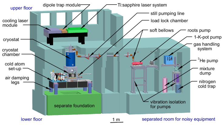
The overall layout of the two-storey laboratory for the HQS experiment is depicted in Fig. 1. The upper floor contains the coupling laser module, the dipole trap module and the titanium sapphire (Ti:sapphire) laser module, which are assembled on an optical table. The optical table is supported by air damping legs and a temperature controlled flow box on top ensures stable conditions. The control units as well as the data acquisition systems are located in the upper floor as well.
The UHV cryostat system and the ultra-cold atom apparatus including the homodyne detection are mounted on a second optical table in the lower floor. This table is also supported by air damping legs and for even better vibration isolation rests on a separate foundation. Above the area with the optical components another temperature controlled flow box is installed. A hole in the ceiling provides access to the upper floor, from where the cryostat is supplied with liquid nitrogen and liquid helium.
Equipment that generates mechanical vibrations like the pumps to operate the DR and the chiller unit to cool the magnetic traps are located in a side room. All pumps are mounted on rubber feet and soft bellows are used along the still and 1-K-pot pumping lines to reduce transmission of vibrations to the cryostat. The gas handling system, the cold traps to remove contaminations from the 3He/4He-mixture and the dump to store the mixture, if the DR is not in operation, are situated in the side room as well.
III Cryogenic UHV system
The cryogenic UHV system consists of a small load lock chamber to introduce mechanical oscillators into the system and a larger chamber with the cryostat on top. With our design membranes can be exchanged in-situ, i.e., without warming-up and without breaking the ultrahigh vacuum. The DR-insert with the cavity set-up is loaded from above into the cryostat so that it extends into the UHV chamber below. This design allows mechanical access to exchange membranes in-situ as well as optical access to align the all-fiber cavity in-situ.
As pointed out above, cryogenically precooling a low-frequency mechanical oscillator is essential to reduce its initial mean phonon occupation number. We decided for a DR cryostat, because simpler cryogenic cooling methods cannot achieve a base temperature in the millikelvin regime while providing a large cooling power. The latter is important to compensate for optical absorption in the membrane and heating due to stray light. Additionally, the UHV environment in the cryostat minimizes damping losses due to the interaction with and adsorption of residual gas molecules.
III.1 Dilution refrigerator
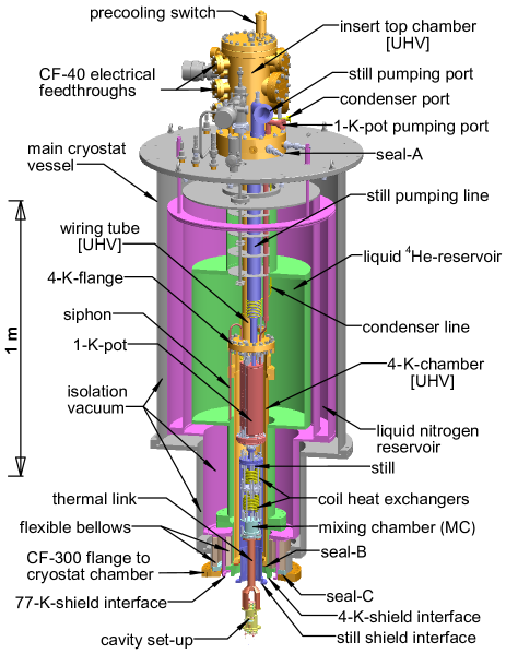
A detailed description of cryogenic cooling schemes, cryostat design, thermal anchoring and thermometry can be found in, e.g., Ref. Pobell et al., 2007. In the following we restrict ourselves to the specifics of our DR cryostat. It is based on a modified version of the Kelvinox 400HA from Oxford Instruments(OI et al., 0000) and shown in Fig. 2. Full UHV-compatibility, meaning that the DR can be baked by internal heaters up to C, is achieved by using CF-type flanges and VCR connectors from Swagelok(Swagelok et al., ) instead of indium seals. Furthermore, we work without step heat exchangers, which deteriorate if heated to C, and instead employ two coil heat exchangers. The main cryostat vessel with the insulation vacuum houses the UHV insert that is surrounded by an inner liquid 4He-reservoir with a volume of 82 l (6 days hold time), and an outer liquid nitrogen reservoir with a volume of 65 l (4 days hold time).
The UHV insert consists of a still pumping line and a condenser line, a 1-K-pot pumping line, a top chamber with all electrical feedthroughs and a wiring tube through which all electrical wires are guided into the 4-K-chamber with the DR unit inside. After attaching the cavity set-up via the thermal link to the MC, the insert is loaded from above into the main cryostat vessel, and connected at Seal-A and Seal-B, as shown in Fig.2. Subsequently, the still-, 4-K-, and 77-K-shields (cf. Sec.III.2) are attached to their corresponding interfaces located at the bottom of the cryostat. Finally, the fully assembled cryostat is loaded onto the cryostat chamber (cf. Sec.III.3). In this way, the UHV-conditions are maintained inside the UHV components of the insert (cf. Fig.2) and the cryostat chamber (cf. Fig.4). Two (edge-welded) flexible bellows at the bottom of the cryostat are introduced to avoid structural damage due to different thermal contraction upon cool down and also provide long thermal paths between different temperature stages for thermal decoupling. Additionally, they also separate the isolating vacuum from the UHV area via Seal-C near the bottom of the cryostat.
To replenish the 1-K-pot with 4He a siphon is fed through the 4-K-flange into the 4He reservoir. The 4He-flow can be adjusted by a needle valve. If the 1-K-pot is full and the needle valve closed (single shot operation) the hold time is more than 12 h. In this mode of operation vibrational noise due to intermixing of incoming normal 4He with the superfluid 4He inside the 1-K-pot can be avoided.(Gorla et al., 2004)
All electrical wires for the heaters and temperature sensors in the DR unit as well as for the piezo elements used to drive the stepper motors of our two fiber alignment stage in our cavity set-up (cf. Sec. III.4) enter the UHV system via electrical feedthroughs at the insert top chamber. They are successively thermally anchored with Vacseal (SPI et al., ) at the 4-K-flange, the 1-K-pot, the still, the cold plate between the two heat exchangers and finally the MC. To minimize thermal conduction via the electrical connection manganin and constantan wires with diameters of 100 m are used to connect the piezo elements and the temperature sensors. Commercially available filters (60 dB attenuation at 100 MHz) are directly mounted on-top of the electrical feedthroughs outside the UHV to reduce radio frequency interference and heating.
To measure the temperatures at the different stages of the DR unit, several temperature sensors are installed: a ruthenium oxide (ROX) sensor at the bottom of the MC, a ROX temperature sensor at the cold plate between two continuous heat exchangers, a ROX sensor at the still, and a ROX and a Cernox sensor at top and bottom of the 1-K-pot, respectively. Carefully calibrated ROX sensors can measure temperatures down to a few mK. To calibrate the ROX sensor at the MC, we used a 60Co nuclear orientation thermometer. (Pobell et al., 2007) Figures of merit for the performance of a DR are its base temperature and its cooling power at 100 mK. Without the cavity set-up attached to the MC we measured a base temperature of mK. Using a heater next to the MC to regulate to 100 mK, we determined a cooling power of 560 W.
A cylindrical thermal link made from high conductive oxygen free copper (OFHC) is used between MC and cavity set-up to bring its final position to the center of the cryostat chamber (see Fig. 2). At this position it is possible to monitor the alignment of the fibers and to exchange membrane in-situ. Coin silver (90% Ag with 10% Cu) screws are used, because their thermal contraction is larger than that of copper at low temperatures, which ensures that the pressed contacts between MC and thermal link as well as between cavity set-up and thermal link becomes tighter after cooling down the system.
Initial cool down to the base temperature in the millikelvin regime takes about 4.5 days. To accelerate the cooling process of the thermally well isolated DR unit, a lozenge-shaped copper piece is used as a mechanical heat switch.(Kingsley et al., 2012) It is operated by a CF-16 UHV rotary feedthrough attached to the top chamber of the insert with its driving rod extending down to the MC. By rotating the thermal switch a mechanical contact can be established or released between the bottom of the 1-K-shield and a strike-plate mounted on the MC.
III.2 Radiation shields with movable shutters
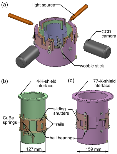
To avoid heating by thermal radiation, home-built cylindrical metallic shields shown in Fig. 3(a) surround the cavity set-up. They are connected to the liquid nitrogen reservoir (77 K), the 4He-reservoir (4.2 K) and the still (0.7 K), respectively. In order to monitor in-situ the alignment of the fiber cavity at low temperatures, four symmetrically placed rectangular apertures are made in each shield. They are in-line with four CF-63 viewports on the cryostat chamber (Sec. III.3). Two orthogonally placed CCD cameras with diffuse light sources at opposite windows are used to observe the positions of the two fibers relative to the membrane inside the cavity. To access the membrane shuttle receptacle with a wobble stick, an additional rectangular aperture is made on all three shields. As shown in Fig. 3(b) and (c), the five apertures in the 4-K-shield as well as in the 77-K-shield can be opened and closed with a rotating shutter system. We do not use shutters for the apertures in the still shield, because tests with apertures in the still shield but no apertures in the 4-K-shield and 77-K-shield have shown no significant increase of .
To move the rotating shutters handles attached to them can be grabbed with the wobble stick. Three positions can be selected: all apertures closed (measurement condition), all apertures open except the one for the wobble stick (during aligning the fiber position relative to the membrane), and all apertures open (exchanging membranes). All the shields and the shutters are made from oxygen free highly conductive copper (OFHC; UNS C10100) and phosphorous deoxidized copper (DHP-Cu; UNS 12200). To minimize the emissivity and to avoid surface degradation due to oxidation over time the copper shields are plated with about 5 m of gold. Flexible copper braids are used to connect the rotating shutters to the radiation shields. Smooth motion of the shutters is ensured by using UHV-compatible oil-free stainless steel ball bearings.
Before the shutters are opened the 3He/4He-mixture has to be put back into the storage dump, because proper circulation cannot be maintained in the presence of this large additional thermal load from room temperature radiation through the open apertures. As a result, the temperature increases continuously over time to about 30 K, if the apertures are open to align the cavity or to exchange the membrane. Subsequent cool down back to the base temperature requires a few hours, depending on the amount of time the apertures were open.
III.3 Ultra-high vacuum chamber assembly
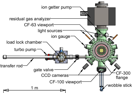
Figure 4 shows the UHV chamber assembly. The cryostat chamber is made of non-magnetic stainless steel (main vessel: 316LN; tubes welded to the vessel: 316L). After manufacturing, a heat treatment (vacuum firing and subsequent bake-out at 200 ∘C for 48 h) has been performed to remove hydrogen dissolved inside the stainless steel material, which reduces hydrogen outgassing. Each chamber is pumped by a turbo molecular pump backed by an oil-free scroll pump. During experiments, these pumps are switched off and the cryostat chamber is only pumped by a vibrationless 300 l/s ion getter pump. The pressure in the UHV system is monitored with an ionization gauge. To detect potential air or helium leaks, a residual gas analyzer is attached to the cryostat chamber.
The cryostat chamber is equipped with four CF-63 viewports, in line with the four sets of optical apertures in the radiation shields (Fig. 3). As described in the previous section, they are used for optical access. A wobble stick with a jaw style pincer head (Ferrovac et al., ) in line with the fifth set of apertures in the radiation shields can be used to exchange membranes and to open or close the rotating shutters. All actions with the wobble stick can be observed through an angled CF-100 viewport above the wobble stick flange.
The whole UHV system including the insert can be baked up to 100 ∘C. The maximum temperature is limited by the materials used to build the DR unit. However, pressures below 510-10 mbar are achieved even without baking if the system is cold, because the large surface area of the radiation shields acts as a powerful cryopump.
III.4 All-fiber MiM cavity set-up
The mode-matched all-fiber MiM cavity set-up is the central component of the optomechanical part of our experiment. It is an asymmetric cavity with different reflectivities of the dielectric coatings at the fiber ends, respectively.(Bick et al., 2016) Both fibers enter the UHV system via CF-16 Swagelok fiber feedthroughs with Teflon gaskets, (Abraham et al., 1998) which are attached to the bottom of the UHV-cryostat chamber. They are guided through tiny holes (1 mm diameter) in the radiation shield assembly and glued into zirconia (ZrO2) ferrules. Each ferrule is glued to the free end of a piezo tube (PZT-8, outer diameter mm, thickness mm and length mm), used to fine-adjust or to scan the cavity length.
To align the MiM cavity, each fiber can be fully adjusted independently with five degrees of freedom (, and ) by piezo-driven Pan-type slip-stick stepper motors (Pan et al., 1993). Translational and angular accuracy are better than 1 nm and better than , respectively. Thus, it is possible to ensure that the fibers are in-line and perpendicular to the membrane. Figure 5 shows the section view of our cavity set-up with the two alignment stages and the membrane in between. It has an outer diameter of 70 mm with an overall height of 135 mm. The cavity housing is made from gold-plated (5m) OFHC copper, which ensures a fast cool down and a homogeneous temperature distribution. The gold plating avoids surface degradation (during assembling and maintenance the cavity set-up in air) and enhances the thermal conductivity through pressed contacts. Most of the screws and all leaf springs are made from CuBe (UNS C17200). Two types of epoxy glues are used, i.e., H20E (electrically conductive) and H77 (electrically insulating), respectively.(Epotek et al., ) All piezo stacks used for the stepper motors have been purchased from PI.(PI et al., ) More technical details regarding the construction of such a positioning stage, how to apply voltages to the piezo stacks to induce the desired motion and how to adjust the step size have been described in Ref. Pan et al., 1993 for single-axis -stage, in Ref. Liebmann et al., 2002 for dual-axis -stage and in Ref. Zhong et al., 2014 for dual-axis -stage.
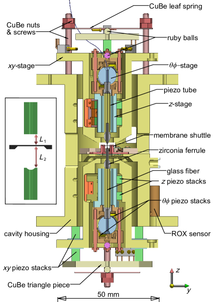
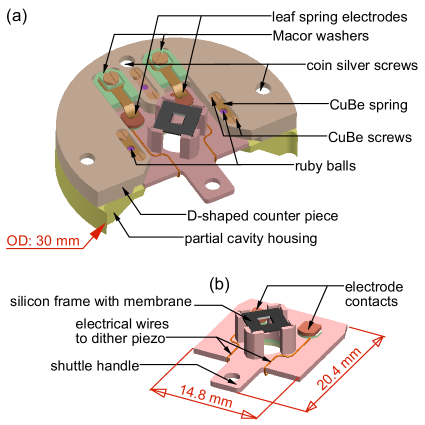
Figure 6(a) shows the shuttle receptacle, which is located in the middle of the cavity housing between the two fiber ends, cf. Fig. 5. The receptacle is a 1 mm slit formed between an integral part of the cavity housing and a D-shaped counter piece attached to it with coin silver screws. If the shuttle is inserted into the slit, three spring loaded ruby balls clamp it tightly. Additionally, two electrical contacts, isolated from the metallic surroundings, are formed via two CuBe leaf springs, which strike two electrically isolated contact pads on the shuttle if inserted. They can be used to drive a dither piezo attached to the shuttle to excite the membrane. Note that after inserting the shuttle, the position of the membrane is fixed and not adjustable. Further alignment of the MiM cavity is done by independently moving each fiber end with respect to the membrane surface in , , , and directions.
The shuttle together with a Si3N4 membrane in its frame is depicted in Fig. 6(b). The shuttle is a rectangular CuBe plate with a central 5 mm hole surrounded by four posts, onto which the silicon frame of the membrane is glued. A handle with a hole, which can be grabbed with the wobble stick, sticks out to one side. Before inserting or extracting the shuttle from the receptacle, both fibers must be fully retracted, so that they cannot be touched by the wobble stick or the shuttle. During the cavity alignment, one fiber is approached from top and the other from below towards the membrane. While the upper fiber is always visible with the CCD cameras, the lower fiber has to approach through the hole in the shuttle. Thereafter, its position can be seen through the gaps between the four posts. Upon further approach towards the membrane it becomes invisible again, because of the 0.2 mm thick silicon frame (see inset in Fig. 5). Hence, to align the lateral positions of the fiber cores relative to each other and relative to the membrane with a precision of about 10 nm, the cavity signal in transmission and reflection has to be monitored (see also Sec. VI). To determine the total cavity length with a precision better than 1 nm, successive cavity resonances generated with the Ti:sapphire laser described in Sec. V can be utilized. Moreover, and can be determined with an accuracy of about 100 nm using white light interferometry. Our method used here is very similar to the one described in Ref.Jiang et al., 2008 for determining the length of very short Fabry-Pérot cavities.
IV Cold atom set-up
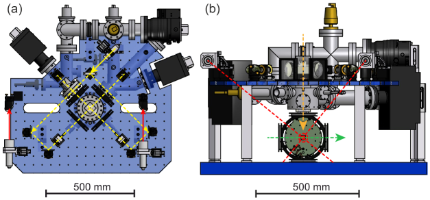
To produce ultra-cold 87Rb atoms a dedicated apparatus has been constructed and placed next to the cryostat on the same optical table in the lower floor; cf. Fig. 1. The set-up (Fig. 7) is based on a scheme consisting of a two-dimensional magneto- optical trap (2D-MOT) to catch atoms from a background gas and a 3D-MOT operating at pressures below mbar. The two different vacuum glass cells are connected via a differential pumping stage allowing for pressures that can differ by a factor of . This setup has the advantage of providing extremely good optical access to the lower 3D-MOT glass cell allowing for different kinds of optical trapping, manipulation and detection schemes, such as optical lattices of different dimensionality, Raman laser configurations or momentum resolved Bragg spectroscopy. (Ernst et al., 2010)
In a typical experimental sequence we start by loading the 3D MOT for s resulting in atom numbers of at temperatures of , where K is the Doppler temperature of 87Rb. Subsequently, the atoms can be further cooled in an optical molasses reducing the temperature to K, which amounts to several times the 87Rb recoil temperature of nK. For the purpose of generating a Bose-Einstein condensate (BEC), we load our atoms in a magnetic trap of hybrid cloverleaf 4D type. Forced evaporation cooling for less than s allows producing Bose-Einstein condensates of particles without any discernible amount of thermal atoms. For continuous experiments our setup is equipped with a crossed optical dipole trap derived from a Nd:YAG laser operated at nm with circular beam waists of m and m. The maximum available optical power at the experiment is W per beam. The BEC inside this dipole trap has an elongated cigar like shape and corresponding trapping frequencies Hz, where gravity points along the -direction. The beam with the larger beam waist can be used to tune between Hz. Thereby we can vary the elongation of the atomic cloud along the direction of the coupling lattice or coupling Raman beams, respectively. For experiments aiming at coupling internal atomic degrees of freedom to the motional state of a mechanical oscillator it is necessary to trap the atoms in a potential that is independent of the particular internal state to avoid fast dephasing. This is guaranteed by using a far detuned optical dipole potential. (Grimm et al., 2000) From the same laser we also derive a two-dimensional optical lattice perpendicular to the coupling lattice (see Sec. V) that enables us to confine the atoms in a three-dimensional periodic potential and to freeze out all continuous degrees of freedom. The properties of the cold atom sample are detected using a flexible absorption imaging system allowing for different magnification ranging from 0.5 to 10.
V Coupling laser system
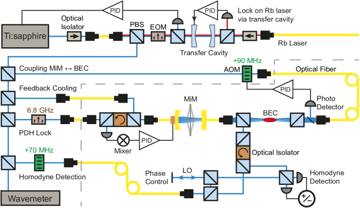
Figure 8 shows the layout of the coupling laser system. To achieve a coupling between the membrane and the ultra-cold atomic cloud, we use a titanium-sapphire laser (Ti:sapphire) operated at a wavelength close to the 87Rb D2 line at a wavelength of nm. This laser can be widely tuned and Pound-Drever-Hall-locked to an external Fabry-Pérot transfer cavity with a free spectral range (FSR) of 1GHz, which is referenced to the 87Rb cooling laser system. The light is divided into four different branches that serve as the coupling beam, the homodyne detection beam to determine the membrane motion, the Pound-Drever-Hall-locking beam for the fiber Fabry-Pérot cavity of the MiM set-up and the feedback beam for active feedback cooling of the membrane. The coupling and detection beams are coupled into the MiM setup from the planar side to allow optimal mode match and thus minimized losses.(Bick et al., 2016) For the less critical feedback and Pound-Drever-Hall beams we choose an incoupling from the curved side of the cavity. Two AOMs in the coupling and detection beam, respectively, shift the frequencies by several tens of MHz in order to prevent unwanted interference between the four different beams. Furthermore, these AOMs can be used to control and actively stabilize the light power in these beams. The coupling beam is focused onto the atomic cloud with a waist size of m and then coupled into the MiM set-up. Afterwards, the reflected light from the MiM set-up interferes with the incoming beam and forms a 1D optical lattice at the position of the atoms providing the basis of the coupling scheme. Our detection beam has a typical power of W at the MiM system and the emerging phase modulation due to the motion of the membrane is resolved through interference with a phase-locked local oscillator beam in a balanced homodyne detection scheme. In order to lock the cavity length of the MiM set-up to the Ti:sapphire laser wavelength we use a Pound-Drever-Hall technique employing sidebands at 6.72 GHz created by a high-frequency resonant phase modulator. The back-reflected beam is detected by a fast photodiode, amplified by two low noise amplifiers with a total gain of 90 dB and mixed down with the local oscillator that drives the phase modulator. In order to modulate the light intensity for the active feedback cooling we use a fiber based, large bandwidth amplitude modulator, which is driven by a digital oscillator. This signal is derived digitally from the homodyne signal after processing through a lock-in amplifier. (ZI et al., )
VI Characterization Measurements
With the cavity set-up attached to the MC and with the rotating shutter system attached to the radiation shields but without in-coupling laser light a minimal temperature mK is currently achieved. If the roots pump is switched off, i.e., only a rotary vane pump is used to circulate the 3He/4He-mixture, the temperature increases to 478 mK. Since this temperature increase is negligible, all measurements shown in this section were performed without roots pump. With a homodyne detection power of 5 W increases further to 485 mK. At the same time the temperature at the MC is mK. Since the cooling power of the non-loaded MC is about 560 W at mK, the total thermal load can be estimated to be mW, if we assume a linear relationship between cooling power and temperature from 100 mK to 178 mK.(Pobell et al., 2007).
We believe that heat radiation is responsible for most of the total thermal load. We estimate an upper bound for the thermal load caused by thermal conduction along the electrical wires of less than 1 W and along the two fibers of less than 11 W and find it to be negligible. Since we do not use shutters on the still-shield, the cavity set-up is directly exposed to radiation from the 4-K-shield. However, we estimate the heat load due to direct radiation heating to be less than 10 W, even if the actual temperature of the 4-K-shield is about 10 K. Another path for heat radiation is funneling: The shutters of the 4-K-shield are about 4 mm larger in size than the apertures they close. Since a gap of about 1 mm exists between the 4-K-shield and the shutters, heat radiation from the 77-K-shield can reach the cavity set-up via multiple reflections between the gold plated inner surface of the shutter and the gold plated outer surface of the 4-K-shield. The amount of heat load by funneling is difficult to estimate. However, after we moved the shutters in front of the 4-K-shield sideways by about 1 mm, so that there is still no direct line of sight between 77-K-shield and cavity set-up, increased by about 10 mK. This finding indicates that currently the shutters do not prevent funneling completely. Possible solutions would be to increase the shutter size relative to the aperture size or to implement shutters on the still-shield.
To analyze the feasibility to realize a HQS with our experimental set-up, we characterize the performance of our millikelvin optomechanical set-up with a high stress Si3N4 membrane (nominal dimensions ) from Norcada (Norcada et al., ). The asymmetric mode-matched cavity employed for the following measurements consists of a planar fiber end with a nominal reflectivity (for incoupling) and a curved fiber end (radius of curvature m) with a nominal reflectivity (for outcoupling).
VI.1 Fiber cavity alignment
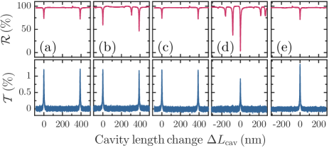
In our set-up it is very important that the cavity can be aligned reliably at low temperatures. We analyze the repeatability of the fiber cavity alignment using the empty fiber cavity. The alignment as well as the measurements shown in Fig. 9 were performed at K with the inspection apertures open and the 3He/4He-mixture in the dump. The on-resonance cavity exhibits its designed 75% intensity reflectivity and 1.5% intensity transmission, which are very close to the calculated values using the nominal reflectivities of the fiber coatings.
From Fig. 9(a), obtained after thorough alignment of the cavity, we determined an empty cavity finesse , which is found to be unchanged up to a cavity length of 25 m. In order to analyze the low-temperature alignment reproducibility we retracted one fiber by 400 m and then reapproached it to the original position. After that procedure the power reflectivity on resonance is slightly lower and additional features appear in the spectrum (see Fig. 9(b)) indicating a decreased mode match. Comparison with independent measurements of the power reflectivity on resonance as a function of lateral fiber position suggests a lateral misalignment of m. The original signal quality could be recovered using a few steps with the -stepper motors shown in Fig.9(c). The described procedure also works when retracting both fibers into their -housings ( mm apart) as required for exchanging the membrane shuttle, and the corresponding results are shown in Figs. 9(d) and (e). The estimated lateral misalignment in Fig.9(d) is m.
VI.2 Homodyne detection of the membrane eigenmodes
To identify the membrane eigenmodes and to characterize the different mechanical and electrical noise sources, we performed homodyne measurements of the thermal Brownian motion of a membrane over a span of 1 MHz using a spectrum analyzer (Rohde & Schwarz FSP)(SA et al., ) with a resolution bandwidth (RBW) of 10 Hz, employing a laser power of 5 W at mK, as shown in Fig. 10. The homodyne detection was calibrated by simulating a defined membrane motion by moving both fiber tips commensurately with respect to the membrane. We used the signal generated by this well-defined membrane motion to determine the corresponding voltage per membrane displacement.
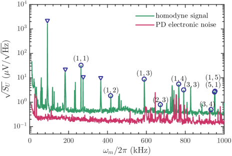
We extracted a noise floor of fm/ around 270 kHz from these measurements, which is on the same order of magnitude as the laser shot noise equivalent of 0.13 fm/ for our set-up at 5 W detection power. We further identified the different membrane eigenmodes by applying the formula with kHz. Since the measured amplitude of a given mode depends on the position of the almost point-like intracavity light mode (waist size m) with respect to the membrane mode function, monitoring a given eigenmode can be employed to optimize the coupling to a desired eigenmode by adjusting the lateral position properly. In Fig. 10 the (1,1)-eigenmode has been optimized by adjusting the two fiber positions with respect to the membrane center. For eigenmodes with a node at the membrane center (both and are even), its amplitude becomes minimal. Consequently, (2,2)- and (2,4)-eigenmodes are not visible. For an ideal square membrane is equal to , while the observed lifting of this degeneracy (cf., the splitting between the (1,5)- and (5,1)-eigenmodes with a frequency difference of kHz), indicates that our particular membrane is not perfectly square.
VI.3 Mode temperature and factor
For the realization of an atom-membrane HQS the mode temperature (related to the phonon number ) and the corresponding mechanical quality factor (related to the thermal decoherence rate ) of the membrane (1,1)-eigenmode are of key importance. The temperature of the (1,1)-eigenmode can be determined using the equipartition theorem according to , where is the spring constant. The effective mass is calculated using kg, (AJ et al., 2015) where g/ is the density of Si3N4 membrane. (Borkje et al., 2012) is obtained by integrating the fitted Lorentzian curve shown in Fig. 11. For the Lorentzian fit, the experimentally determined noise floor of 0.3 fm/ is used as a fixed background and the linewidth is fixed to the value deduced from the ringdown measurement shown in the inset of Fig.11. We believe that the quality of our fit indicates that the dephasing (Schneider et al., 2014) is not significant in our measurements, however, it cannot be fully ruled out without further studies in the future. From the Lorentzian fit we obtain a mode temperature K, which is larger than the environmental temperature mK. Reasons for the increased mode temperature could be radiative heating through the not perfectly overlapping rotating shutters, (Chan et al., 2011) temperature gradients between the membrane and the MiM set-up body,(DLMcAuslan et al., 2016) residual mechanical vibrations in the set-up, (Yuan et al., 2015) or electromagnetic noise picked up and transduced by the dither piezo. We have furthermore carefully checked that the mode temperature does not depend on the laser power used for homodyne detection, by changing the power by half an order of magnitude (up to 25 W) without observing any mode temperature change.
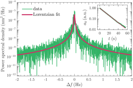
The inset of Fig.11 shows the normalized ringdown curve of the (1,1)-eigenmode obtained at a cavity set-up temperature of mK. Fitting an exponential decay function to the data we find a decay time s, which corresponds to . Similar large -factors for high stress Si3N4 membranes in this temperature regime have been reported recently.(Jayich et al., 2012; Yuan et al., 2015) The resulting mechanical decay rate deduced from the ringdown measurement reads Hz.
VI.4 Optomechanical coupling
Since our envisaged HQS relies on coupling ultra-cold atoms to a membrane via light, the strength of the optomechanical coupling is a crucial parameter. For a Fabry-Pérot cavity (length: ) with a moving end mirror, the optomechanical coupling strength is given by , where the cavity frequency equals to the laser frequency . In the MiM configuration the optomechanical coupling strength is defined by , where is the intracavity position of the membrane. Using the optical methods mentioned in Sec. III.4, we find m, m and m.
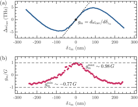
Figure 12(a) displays the cavity resonance frequency shift when the membrane is moved by relative to its rest position at m. From its derivative displayed in Fig. 12(b), we find a maximum optomechanical coupling GHz/nm. Moreover, depends on the membrane intracavity position, which shows a slight asymmetry.
| kHz | THz | ||
|---|---|---|---|
| 23.7 m | |||
| mHz | GHz | ||
| kg | 60 | ||
| m | 50 …120 | ||
| GHz/nm | GHz/nm | ||
| kHz | Hz |
To fully characterize our MiM cavity, several cavity optomechanical parameters are of importance. They are listed in Table 1. We define the finesse by , where GHz is the full width at half maximum of the MiM cavity resonance. In a MiM configuration (like ) depends on the absolute position of the membrane inside the cavity. Since , our MiM cavity is in the so-called bad cavity limit. As mentioned before, this situation cannot be avoided, because coupling a membrane to atoms in an optical lattice via retroreflected light automatically limits the achievable finesse of the cavity.
The zero point fluctuation of the (1,1)-eigenmode is m. The maximum single photon optomechanical coupling strength is kHz. Finally, the product Hz of the (1,1)-eigenmode is larger than Hz. This is an essential condition for quantum ground state cooling using radiation pressure, (Aspelmeyer et al., 2014) which is apparently the case for our set-up.
VII Summary
An all-fiber MiM cavity set-up has been constructed in cryogenic UHV environment as well as an apparatus to produce ultra-cold atoms, which can subsequently be loaded into an optical lattice. The MiM cavity can be accurately aligned in-situ using two low-temperature compatible fiber positioning stages with five degrees of freedom each. The motional state of the membrane can be detected with a state-of-the-art homodyne detection scheme. At the currently achievable minimal temperature of about 480 mK, we determined all key parameters that characterize our optomechanical system for a high-stress Si3N4 membrane. Comparing our values with the requirements suggested in Ref. Vogell et al., 2013, we conclude that it is feasible to realize an atom-membrane HQS with our experimental set-up. This would allow for sympathetically cooling the membrane into its quantum ground state (Vogell et al., 2013; AJ et al., 2015) and would moreover pave the way for coherent state transfer and entanglement of the HQS.
Acknowledgments
The authors thank M. Nitschke for his help with assembling the all-fiber MiM cavity set-up, O. Hellmig for his help with the fiber processing and our machine shop, particularly R. P. Benecke, J. Path for machining the radiation shields and the cavity housings. Further, we thank the engineering team from Oxford Instruments, particularly H. Agrawal, S. Kingsley and R. Viana, for their technical support. Financial support from the ERC Advanced grant ’FURORE’ as well as the DFG via grants SFB668-A5, Wi1277/29-1, BE4793/2-1 and SE717/9-1 is gratefully acknowledged.
References
- Kurizki et al. (2015) G. Kurizki, P. Bertet, Y. Kubo, K. Mølmer, D. Petrosyan, P. Rabl, and J. Schmiedmayer, Proc. Natl. Acad. Sci. U. S. A. 112, 3866 (2015).
- Aspelmeyer et al. (2014) M. Aspelmeyer, T. J. Kippenberg, and F. Marquardt, Rev. Mod. Phys. 86, 1391 (2014).
- O’Connell et al. (2010) A. D. O’Connell et al., Nature 464, 697 (2010).
- Teufel et al. (2011) J. D. Teufel et al., Nature 475, 359 (2011).
- Chan et al. (2011) J. Chan, T. P. M. Alegre, A. H. Safavi-Naeini, J. T. Hill, A. Krause, S. Gröblacher, M. Aspelmeyer, and O. Painter, Nature 478, 89 (2011).
- Vogell et al. (2013) B. Vogell, K. Stannigel, P. Zoller, K. Hammerer, M. T. Rakher, M. Korppi, A. Jöckel, and P. Treutlein, Phys. Rev. A 87, 023816 (2013).
- AJ et al. (2015) A. Jöckel, A. Faber, T. Kampschulte, M. Korppi, M. T. Rakher, and P. Treutlein, Nat. Nanotech. 10, 55 (2015).
- Xiang et al. (2013) Z. Xiang, S. Ashhab, J. Q. You, and F. Nori, Rev. Mod. Phys. 85, 623 (2013).
- Hammerer et al. (2009) K. Hammerer, M. Aspelmeyer, E. S. Polzik, and P. Zoller, Phys. Rev. Lett. 102, 020501 (2009).
- Wallquist et al. (2010) M. Wallquist, K. Hammerer, P. Zoller, C. Genes, M. Ludwig, F. Marquardt, P. Treutlein, J. Ye, and H. J. Kimble, Phys. Rev. A 81, 023816 (2010).
- Bariani et al. (2014) F. Bariani, S. Singh, L. F. Buchmann, M. Vengalattore, and P. Meystre, Phys. Rev. A 90, 033838 (2014).
- Bariani et al. (2015) F. Bariani, H. Seok, S. Singh, M. Vengalattore, and P. Meystre, Phys. Rev. A 92, 043817 (2015).
- Treutlein et al. (2007) P. Treutlein, D. Hunger, S. Camerer, T. W. Hänsch, and J. Reichel, Phys. Rev. Lett. 99, 140403 (2007).
- Chen et al. (2009) W. Chen, K. Zhang, D. S. Goldbaum, M. Bhattacharya, and P. Meystre, Phys. Rev. A 80, 011801(R) (2009).
- Wang et al. (2006) Y.-J. Wang, M. Eardley, S. Knappe, J. Moreland, L. Hollberg, and J. Kitching, Phys. Rev. Lett. 97, 227602 (2006).
- Hunger et al. (2010) D. Hunger, S. Camerer, T. W. Hänsch, D. König, J. P. Kotthaus, J. Reichel, and P. Treutlein, Phys. Rev. Lett. 104, 143002 (2010).
- Vogell et al. (2015) B. Vogell, T. Kampschulte, M. T. Rakher, A. Faber, P. Treutlein, K. Hammerer, and P. Zoller, New J. Phys. 17, 043044 (2015).
- Bick et al. (2016) A. Bick, C. Staarmann, P. Christoph, O. Hellmig, J. Heinze, K. Sengstock, and C. Becker, Rev. Sci. Instrum. 87, 013102 (2016).
- Thompson et al. (2008) J. D. Thompson, B. M. Zwickl, A. M. Jayich, F. Marquardt, S. M. Girvin, and J. G. E. Harris, Nature 452, 72 (2008).
- Jessen et al. (2014) F. Jessen et al., Appl. Phys. B 116, 665 (2014).
- Poot et al. (2012) M. Poot and H. S. J. van der Zant, Phys. Rep. 511, 273 (2012).
- Pobell et al. (2007) F. Pobell, in Matter and Methods at Low Temperatures, Springer, 2007.
- OI et al. (0000) Oxford Instruments, Tubney Woods, OX135QX, UK.
- (24) Swagelok Inc., 29500 Solon Road, Solon, OH 44139, USA.
- Gorla et al. (2004) P. Gorla, C. Bucci, and S. Pirro, Nucl. Instrum. Methods Phys. Res., Sect. A 520, 641 (2004).
- (26) SPI Supplies / Structure Probe, Inc., 206 Garfield Ave, West Chester, PA 19380-4512, USA.
- Kingsley et al. (2012) S. C. J. Kingsley, H. Jones, A. Twin, H. Agrawal, A. Matthews, G. J. Batey, and M. Cuthbert, J. Phys.: Conf. Ser. 400, 052012 (2012).
- (28) Ferrovac GmbH, Thurgauerstrasse 72, CH 8050 Zürich.
- Abraham et al. (1998) E. R. I. Abraham, and E. A. Cornell, Appl. Opt. 37, 1762 (1998).
- Pan et al. (1993) S. H. Pan, International Patent publication No. WO 93/19494 (30 September 1993).
- (31) Epoxy Technology Inc., Billerica, MA 01821, USA.
- (32) PI Ceramic GmbH, Lindenstrasse, 07589 Lederhose, Germany.
- Liebmann et al. (2002) M. Liebmann, A. Schwarz, S. M. Langkat, and R. Wiesendanger, Rev. Sci. Instrum. 73, 3508 (2002).
- Zhong et al. (2014) H. Zhong, A. Schwarz, and R. Wiesendanger, Rev. Sci. Instrum. 85, 045006 (2014).
- Jiang et al. (2008) Y. Jiang, Appl. Opt. 47, 925 (2008).
- Ernst et al. (2010) P. T. Ernst, S. Götze, J. S. Krauser, K. Pyka, D.-S. Lühmann, D. Pfannkuche, and K. Sengstock, Nat. Phys. 6, 56 (2010).
- Grimm et al. (2000) R. Grimm, M. Weidemüller, and Y. B. Ovchinnikov, Adv. At. Mol. Opt. Phys. 42, 95 (2000).
- (38) HF2LI, Zurich Instruments AG, Technoparkstrasse 1, 8005 Zurich, Switzerland.
- (39) Norcada Inc., Edmonton, AB T6E 5B6, Canada.
- (40) FSP Spectrum Analyzer, Rohde & Schwarz GmbH & Co. KG, Mühldorfstraße 15, 81671 Munich, Germany.
- Borkje et al. (2012) K. Børkje and S. M. Girvin, New J. Phys. 14, 085016 (2012).
- Schneider et al. (2014) B. H. Schneider, V. Singh, W. J. Venstra, H. B. Meerwaldt, and G. A. Steele, Nat. Commun. 5, 5819 (2014).
- DLMcAuslan et al. (2016) D. L. McAuslan, G. I. Harris, C. Baker, Y. Sachkou, X. He, E. Sheridan, and W. P. Bowen, Phys. Rev. X 6, 021012 (2016).
- Yuan et al. (2015) M. Yuan, M. A. Cohen, and G. A. Steele, Appl. Phys. Lett. 107, 263501 (2015).
- Jayich et al. (2012) A. M. Jayich et al., New J. Phys. 14, 115018 (2012).