Landau level evolution driven by band hybridization in mirror symmetry broken ABA-stacked trilayer graphene
Abstract
Layer stacking and crystal lattice symmetry play important roles in the band structure and the Landau levels of multilayer graphene. ABA-stacked trilayer graphene possesses mirror-symmetry-protected monolayer-like and bilayer-like band structures. Broken mirror symmetry by a perpendicular electric field therefore induces hybridization between these bands and various quantum Hall phases emerge. We experimentally explore the evolution of Landau levels in ABA-stacked trilayer graphene under electric field. We observe a variety of valley and orbital dependent Landau level evolutions. These evolutions are qualitatively well explained by considering the hybridization between multiple Landau levels possessing close Landau level indices and the hybridization between every third Landau level orbitals due to the trigonal warping effect. These observations are consistent with numerical calculations. The combination of experimental and numerical analysis thus reveals the entire picture of Landau level evolutions decomposed into the monolayer- and bilayer-like band contributions in ABA-stacked trilayer graphene.
pacs:
Recent progress on the study of quantum Hall effect (QHE) in graphene revealed novel physics such as half-integer QHE in monolayer graphene Zhang et al. (2005); Novoselov et al. (2005), spin-valley quantum Hall ferromagnetism Young et al. (2012), spin phase transition and quantum spin Hall state at charge neutrality point Maher et al. (2013); Young et al. (2014), and Hofstadter’s butterfly in graphene/h-BN superlattice Hunt et al. (2013); Ponomarenko et al. (2013); Dean et al. (2013).
Graphene has a unique band structure and related properties drastically depending on layer number, stacking, and symmetry. Monolayer graphene (MLG), AB-stacked bilayer graphene (BLG) and ABC-stacked trilayer graphene (TLG) posess linear, parabolic, and cubic band dispersions, respectively. These systems have inversion symmetry and breaking inversion symmetry results in band gap formation. For the case of multilayer graphene, the inversion symmetry of the system can be controlled with perpendicular electric field Oostinga et al. (2007); Zhang et al. (2009); Shioya et al. (2012); Lui et al. (2011); Khodkov et al. (2015). In these multilayer systems, the integer and fractional quantum Hall phase transitions are also tunable with a perpendicular electric field Weitz et al. (2010); Kim et al. (2011); Velasco Jr. et al. (2012); Maher et al. (2014); Young et al. (2014); Lee et al. (2014); Velasco Jr. et al. (2014); Lee et al. (2016); Shi et al. (2016).
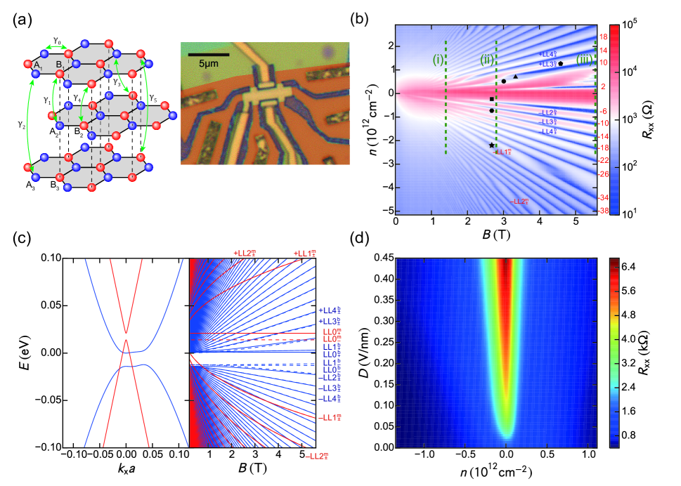
Trilayer graphene can have a different kind of stacking, called ABA-stacking (Fig. 1(a) left). ABA-stacked TLG has mirror symmetry. Reflecting this mirror symmetry, ABA-stacked TLG posesses a combined MLG-like and BLG-like band structure. The MLG-like band corresponds to mirror-symmetric wave function, whereas the BLG-like band corresponds to mirror-antisymmetric wave function. These two bands can hybridize when mirror symmetry is broken. In previous works, the mirror symmetry of the system is controlled by a perpendicular electric field Craciun et al. (2009); Henriksen et al. (2012); Zou et al. (2013); Lee et al. (2013). Therefore, ABA-stacked TLG is a novel platform to investigate the effect of band hybridization on the QHE. Under a perpendicular electric field, ABA-stacked TLG is expected to show complex but rich Landau level (LL) evolution, such as LL crossings and valley splitting due to the LL index dependent hybridization processes Koshino and McCann (2010); Morimoto and Koshino (2013); Serbyn and Abanin (2013). These featuers, however, have not yet been well revealed. In gapped bilayer graphene, it has been shown that the trigonal warping effect results in three fold degenerate LLs at low magnetic field and small carrier density regime Varlet et al. (2014). In mirror symmetry broken ABA-stacked trilayer graphene, it is also expected that the trigonal warping affects LL orbital hybridization to induce anti-crossings between specific LLs Serbyn and Abanin (2013). At such anti-crossing points, the LL orbital states are tunable by an electric field; this may allow for further study on many-body phenomena such as quantum Hall ferromagnetism and fractional qunatum Hall effect. Previous studies on the QHE in ABA-stacked TLG have revealed LL crossings due to the existence of independent MLG-like and BLG-like bands and unconventional sequence of the quantum Hall plateaus; which is explained by taking into account the all hopping parameters to (Fig. 1(a) left) and the onsite energy difference between A1, B2, A3 and B1, A2, B3 Koshino and McCann (2011); Taychatanapat et al. (2011); Jhang et al. (2011); Henriksen et al. (2012); Lee et al. (2013). On the other hand, the perpendicular electric field dependence of the QHE in ABA-stacked TLG remained experimentally unclear, though the emergence or stabilization of a few novel quantum Hall plateaus have been observed Henriksen et al. (2012); Lee et al. (2013).
In this study, we reveal detailed picture of the evolution of the LL structure in ABA-stacked TLG under a perpendicular electric field. Importantly, all tight-binding parameters, to and , which describe the nature of the bulk graphite, play important roles in the LL structures of the ABA-stacked TLG as well as the onsite energy differences induced by an electric field. By applying perpendicular electric field, we find series of LL crossings and anti-crossings which originate from the hybridized MLG-like and BLG-like bands by breaking the mirror symmetry. We also observe anti-crossing structures mediated by the trigonal warping effect, which hybridizes LLs with the LL index difference of integer times 3, for both electron and hole carriers. These behaviors are well reproduced by numerical calculations based on the tight-binding model with the MLG-like and BLG-like LL orbital basis, involving all tight-binding parameters to , and average onsite energy differences between the layers induced by the electric field.
TLG is encapsulated between h-BN layers in order to achieve a high carrier mobility and to apply a higher electric field than that for suspended devices (Fig. 1(a) right). Both graphene and h-BN were obtained via mechanical exfoliation. The number of graphene layers was confirmed optically via a contrast measurement. As described below, the stacking of the TLG was confirmed as ABA from the measurement of the Landau fan diagram. We used pickup technique to fabricate the BN/TLG/BN stack and made the Ohmic contacts to graphene from the edge Wang et al. (2013). To control the carrier density () and the perpendicular displacement electric field () independently, we adopt a dual-gate structure Oostinga et al. (2007). All measurements were performed at 1.7 K using VTI cryostat unless mentioned.
| LL | Wave function | LL | Wave function |
|---|---|---|---|
| LL | Energy |
|---|---|
The Landau fan diagram at zero is shown in Fig. 1(b). The top and back gate voltages are converted to and using the estimated top and back gate capacitances (see Fig. 1(d)). We observe a number of LL crossings and asymmetry between the electron side and the hole side. These features have been reported in ABA-stacked TLG Taychatanapat et al. (2011); Lee et al. (2013), and are accounted for by the coexistence of MLG-like and BLG-like bands, which are gapped and energetically detuned from each other owing to the tight-binding parameters , , , and defined by the onsite energy of each layer, , , and .
We numerically calculated the band structure around K point (left graph) and dependence of the LLs energies at (right graph) for comparison as shown in Fig. 1(c). The calculation was performed using the tight-binding model Koshino and McCann (2009, 2011) with the parameters, and adopted from Ref. Taychatanapat et al. (2011). Approximated wave functions of the LLs for the low energy at are summarized in Table 1. We define labeling of the LLs in the mirror-symmetric monolayer (m) and mirror-antisymmetric bilayer (b) by LL orbital basis. (Note is mirror-symmetric owing to the antisymmetric property of orbitals.) Their energies, derived analytically by neglecting the small correction by , are shown in Table 2 for the small LL indices. The LL labels are shown visually in Fig. 1(c) (right).
By comparing Fig. 1(b) with Fig. 1(c), the LLs marked by the pentagon, hexagon, and stars in Fig. 1(b) are identified as , and , respectively. The LLs marked by the triangle and circle in Fig. 1(b) are identified as either LL or LL. The LL indicated by the square mark in Fig. 1(b) is identified as either LL or LL. Depending on the tight-binding parameters such as , and , the order of the LL energies with small indices changes (see Table 2)Serbyn and Abanin (2013). Therefore, we cannot uniquely identify the indices for the LLs indicated by the triangle, circle and square marks.
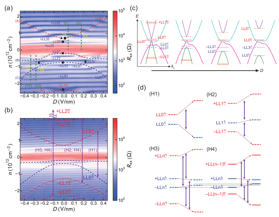
We then investigated the dependence of the transport characteristics. modifies the band structure and induces hybridization between the MLG-like and BLG-like bands. Fig. 1(d) shows the and dependences of the longitudinal resistance measured at 10K at . The and values were calculated using the top and back gate capacitances, which were estimated from the slope of the peak position in the plane defined by the top and back gate voltages and the known parameters of the gate insulators: The thickness, and dielectric constant of is 285nm, and 3.9, respectively, and the thickness of the top, and bottom h-BN layers is 44.1nm, and 52.7nm, respectively. The peak at increases as increases. This is understood by the reduction of the density of states around the charge neutrality point (CNP) by the band hybridization due to the mirror symmetry breaking under Koshino and McCann (2009); Henriksen et al. (2012). Such band evolution with , expected from the tight-binding model with full parameters Koshino and McCann (2009); Serbyn and Abanin (2013), is shown in Fig. 2(c).
Figs. 2(a), and 2(b) show the and dependences of for , and , respectively. The measured along in Figs. 2(a), and 2(b) corresponds to the measured along the broken green lines (i), and (ii) in Fig. 1(c), respectively. In Figs. 2(a) and 2(b), we see a number of LLs parallel to the axis. By comparing them with Fig. 1(c) at , most of these LLs, such as the LL marked by the pentagon (), are found to originate from the BLG-like bands. In addition, several sequences of LL crossings identified by the kinks of the parallel LLs are observed in Figs. 2(a) and 2(b). We put eye guides over some of the LLs which show characteristic evolution with leading to LL crossings. As shown in Fig. 2(c), with increasing , the MLG-like bands move away from each other while the BLG-like bands gradually overlap due to the band hybridization. It is therefore expected that most of the LLs in the MLG-like bands move away from the charge neutrality point (CNP) while most of the LLs in the BLG-like bands gradually approach the CNP.
These trends are clearly observed in Fig. 2(b). By following the LLs indicated by the eye guides shown in red and comparing them with those in Fig. 1(b) at , it is found that these LLs originate from the MLG-like bands. One of the LLs indicated by the eye guides shown in blue quickly moves away from the CNP with . However, in comparison with Fig. 1(b), this LL is found to originate from the BLG-like band.
The detailed evolution of LLs under is understood by considering
the sublattice degree of freedom
of LL wave functions summarized in Table 1 and their hybridization.
Note that is the LL orbital with index .
affects , which is half of the energy detuning between the top and bottom layers.
Under , (monolayer)
and (bilayer) of the same and valley hybridize.
From Table 1, we can identify four kinds of such hybridization processes:
(H1) and
(H2) and
(H3) and ()
(H4) and ().
We schematically show these processes in Fig. 2(d).
In (H1), two LLs, and , move away from each other.
In the rest of (H2), (H3), and (H4), two LLs in the MLG-like bands
and one or two LLs in the BLG-like bands hybridize.
For not too small , the LLs in the BLG-like bands usually stay between
the two LLs in the MLG-like bands.
Therefore, the two LLs in the MLG-like bands move away from each other for increasing .
On the other hand, the LLs in the BLG-like bands are repelled by them from both sides and
slightly get closer to each other.
Note in the range studied here, hybridization between and has a minor influence on the LLs owing to the large energy gap between them. Therefore the energy of is almost unchanged with . and , which are polarized to , are also expected to be almost independent of .
In Fig. 2(c), we schematically show the expected evolution of the specific LLs with . The top of the valence band of the BLG-like bands splits off into the top of the green-colored band and that of the magenta-colored band owing to the hybridization with the valence band of the MLG-like bands. One of the hybridized bands then moves away towards the lower energy and forms a new valence band (green). This process leads to the observation that moves away with other LLs of the MLG-like bands with increasing , since only the top of the green-colored band has the BLG-like component and the rest originates from the MLG-like components. On the other hand, the top of the valence band of the MLG-like bands (top of the band colored with light blue) remains unchanged with although there is hybridization with the BLG-like band. This leads to the observation in Fig. 2(a) that the energy of as well as those of LLs in the BLG-like bands remains almost constant.
From the above considerations, we identified that the LL marked by the triangle, circle, and square in Fig. 2(a) are , , and , respectively. The hybridization process (H1) separates and with increasing while stays at the constant energy owing to the weak influence of the orbitals. Note that evolutions of these LLs are independent (common in Figs. 2(a) and 2(b)) around . This further supports that these are the zeroth LLs, representing the edges of the bands as described in Fig. 2(c).
However, in Fig. 2(a) the eye guide (B) passes through at , and becomes almost independent of for . In contrast, the eye guide (C), which passes through at , shifts away from for . The observed behavior around is interpreted as the anti-crossing between and . It has been pointed out that the trigonal warping term hybridizes every third LLs of the BLG-like bands Serbyn and Abanin (2013). This means that the LLs of the BLG-like bands which mainly consist of , are influenced by . Therefore, when we consider the evolution of and by the hybridization under , , , also have to be taken into account.
In contrast to , which shows anti-crossing with , remains unaffected. Therefore, , marked by the diamonds in Fig. 2(a), splits off from , crosses over the anti-crossing structure, and merges again with . Note this is the first observation of the trigonal warping mediated valley splitting.
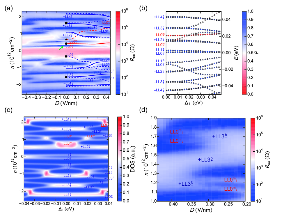
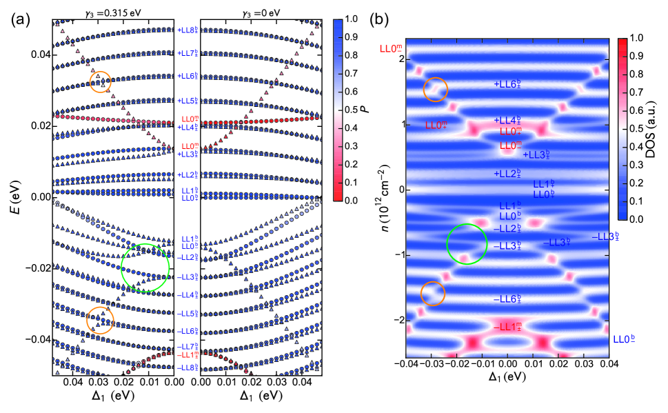
To further confirm this scenario, we show numerical calculations of LLs energies vs at , for (left graph) and (right graph) in Fig. 3(a), where is half the energy detuning between the top and bottom layers, which is controlled by . The calculation was based on Ref. Serbyn and Abanin (2013). Here, we used the same tight-binding parameters as used for the calculation of Fig. 1(c). The experimental result (Fig. 2(a)) including the anti-crossing described above is well reproduced in the left graph of Fig. 3(a). We clearly see the anti-crossing structure between and for (indicated by the green circle), but not for . Though, we see small anti-crossing structures between and , and for in the calculation (indicated by the orange circles), they are not visible in Fig. 2(a). This is attributed to line broadening of the LLs. In Fig. 3(b), we show the and dependences of the LLs density of states (DOS) calculated from the energy level in Fig. 3(a) (left graph). Here the DOS of each LL is assumed as: using the level broadening , where , and are the Planck constant, and elementary charge, respectively Taychatanapat et al. (2011). We find good agreement of this calculation with the experimental result in Fig. 2(a). Note that the order of some LLs in Figs. 3(a) and 3(b) is different from that in Fig. 2(a). For example, the order of and , which is determined by and (see Table 2), is opposite. This is probably due to the environmental difference or the imperfection of the estimation of the tight binding parameters in previous work Taychatanapat et al. (2011) in which is neglected.
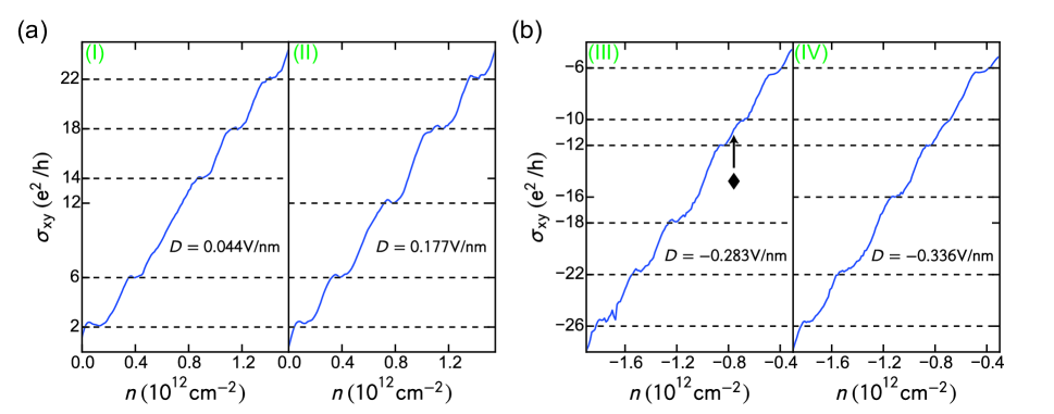
The consistency of the LLs assignment between the experiment and calculation is further confirmed by investigating the degeneracy of the observed LLs. The LLs indicated by the eye guides (A) and (C) ( and ) in Fig. 2(a) are considered to be valley polarized to . Therefore, the filling factor should change by two across these lines. Fig. 4 shows the dependence of the Hall conductivity at different simultaneously measured with in Fig. 2(a). (I) to (IV) indicate the correspondence between the green broken lines (I) to (IV) in Fig. 2(a). In Fig. 4(a), the filling factor around changes from 14 (left graph) to 12 (right graph). Also, in Fig. 4(b), the filling factor around changes from -18 (left graph) to -16 (right graph). These observations are consistent with the interpretation that the evolving LLs indicated by the eye guides (A) and (C) are valley polarized. In the left graph of Fig. 4(b), we see the change of the filling factor from -12 to -10 around across the LL marked by the diamonds in Fig. 2(a). Therefore, this LL has two-fold degeneracy. This is also consistent with the interpretation that the anti-crossing between and results in the valley splitting of and the LL marked by the diamonds is .
Finally, we show the LLs evolution with and at a high of in Fig. 5(a). The measured along in Fig. 5(a) corresponds to the measured along the broken green line (iii) in Fig. 1(c). At this , many fine structures are visible, for instance spin splittings of LLs for and . Fig. 5(b) shows numerically calculated dependence of the LLs energies at , using the same tight-binding parameters as in the calculation of Fig. 3(a). In Fig. 5(c), we show the and dependences of the LLs DOS calculated in the same manner as used for the calculation of Fig. 3(b). The LLs evolution in Fig. 5(a) compares well to the calculation of Figs. 5(b) and 5(c). From this comparison, we identify the LLs evolution as indicated by the eye guides in Fig. 5(a).
Around , we see a kink structure in the evolution of indicating the presence of an additional LL crossing. and are the possible crossing states, but , and (see Table 2) should be carefully evaluated to judge between them.
In Fig. 5(a), in addition to the anti-crossing between and , we also see anti-crossing between and . This is in contrast with the case at where and degenerate but don’t hybridize at (see Fig. 2(a)). Under such a high , shifts to the high energy with , leading to the these LLs crossings at non-zero . This observation indicates that both the trigonal warping term () that hybridizes and and the mirror symmetry breaking by that hybridizes and (H1) are required to form the anti-crossing structure.
In Fig. 5(d), we magnified the region of the anti-crossing between and for . While the process of the anti-crossing, spin splitting of disappears and recovers again across the anti-crossing. This observation is also consistent with anti-crossings, across which the LL index is preserved.
We also observe an effect of the hybridization (H3) and (H4) in Fig. 5(a). It is the valley splitting of for . mainly hybridizes with through the process (H4) while mainly hybridizes with through (H3). Since the energy difference between and is smaller than that between and , – hybridization is stronger than – . This results in valley splitting.
Through out the paper we neglected intervalley hybridization and assumed that two valley states behave independently. The actual device has rough edges because it was shaped by dry etching and therefore may experience intervalley hybridization of the edge states. However, this will not affect the bulk LLs which we mainly discussed above. In the counter-propagating edge transport regime, electron and hole channels coexist and the channel number is influenced by hybridization of edge states. In the regime at and (indicated by a green arrow in Fig. 5(a)), usual two chiral edge transport ( and ) has been observed inspite of the expected counter-propagating edge transport which consists of four electron channels and two hole channels. This can involve the intervalley hybridization of the edge states by rough edges where the total edge states are reduced to two chiral edge states.
In summary, we observed LL crossings under an electric field in ABA-stacked trilayer graphene, and find that the overview of the LL evolution is consistent with the theory of hybridized MLG-like and BLG-like bands. The observed LL evolution shows a variety of valley and orbital dependences. We find that it is explained by considering the hybridization between the multiple LLs sharing the same LL orbital and valley and the hybridization between every third LL orbitals due to the trigonal warping term . We also find pronounced agreement between our experimental observations and numerical calculation based on the tight binding model Serbyn and Abanin (2013). We finally revealed the entire picture of the LL evolution with electric field in ABA-stacked trilayer graphene, and showed a vatiery of quantum Hall phase can be achieved via the mirror symmetry breaking using electric field. While preparing the manuscript, we found related works on the quantum Hall phases achieved in different regimes Campos et al. (2016); Stepanov et al. (2016).
Acknowledgements.
Y. S. acknowledges support from JSPS KAKENHI Grant Number JP13J07387 and JSPS Program for Leading Graduate Schools (MERIT). M. Y. acknowledges support from Canon Foundation and JSPS KAKENHI Grant Number JP25107003. K. Watanabe and T. T. acknowledge support from JSPS KAKENHI Grant Number JP15K21722 and the Elemental Strategy Initiative conducted by the MEXT, Japan. T. T. acknowledges support from JSPS Grant-in-Aid for Scientific Research A (No. 26248061) and JSPS Innovative Areas “Nano Informatics” (No. 25106006). K. Wang and P. K. acknowledge support from ARO MURI (W911NF-14-1-0247). S. T. acknowledges support from JSPS Grant-in-Aid for Scientific Research S (No. 26220710) and A (No. 16H02204). Y. S. and T. Y. contributed equally to this work.References
- Zhang et al. (2005) Y. Zhang, Y.-W. Tan, H. L. Stormer, and P. Kim, Nature 438, 201 (2005).
- Novoselov et al. (2005) K. S. Novoselov, A. K. Geim, S. V. Morozov, D. Jiang, M. I. Katsnelson, I. V. Grigorieva, S. V. Dubonos, and A. A. Firsov, Nature 438, 197 (2005).
- Young et al. (2012) A. F. Young, C. R. Dean, L. Wang, H. Ren, P. Cadden-Zimansky, K. Watanabe, T. Taniguchi, J. Hone, K. L. Shepard, and P. Kim, Nat. Phys. 8, 550 (2012).
- Maher et al. (2013) P. Maher, C. R. Dean, A. F. Young, T. Taniguchi, K. Watanabe, K. L. Shepard, J. Hone, and P. Kim, Nat. Phys. 9, 154 (2013).
- Young et al. (2014) A. F. Young, J. D. Sanchez-Yamagishi, B. Hunt, S. H. Choi, K. Watanabe, T. Taniguchi, R. C. Ashoori, and P. Jarillo-Herrero, Nature 505, 528 (2014).
- Hunt et al. (2013) B. Hunt, J. D. Sanchez-Yamagishi, A. F. Young, M. Yankowitz, B. J. LeRoy, K. Watanabe, T. Taniguchi, P. Moon, M. Koshino, P. Jarillo-Herrero, and R. C. Ashoori, Science 340, 1427 (2013).
- Ponomarenko et al. (2013) L. A. Ponomarenko, R. V. Gorbachev, G. L. Yu, D. C. Elias, R. Jalil, A. A. Patel, A. Mishchenko, A. S. Mayorov, C. R. Woods, J. R. Wallbank, M. Mucha-Kruczyński, B. A. Piot, M. Potemski, I. V. Grigorieva, K. S. Novoselov, F. Guinea, V. I. Fal’ko, and A. K. Geim, Nature 497, 594 (2013).
- Dean et al. (2013) C. R. Dean, L. Wang, P. Maher, C. Forsythe, F. Ghahari, Y. Gao, J. Katoch, M. Ishigami, P. Moon, M. Koshino, T. Taniguchi, K. Watanabe, K. L. Shepard, J. Hone, and P. Kim, Nature 497, 598 (2013).
- Oostinga et al. (2007) J. B. Oostinga, H. B. Heersche, X. Liu, A. F. Morpurgo, and L. M. K. Vandersypen, Nat. Mater. 7, 151 (2007).
- Zhang et al. (2009) Y. Zhang, T.-T. Tang, C. Girit, Z. Hao, M. C. Martin, A. Zettl, M. F. Crommie, Y. R. Shen, and F. Wang, Nature 459, 820 (2009).
- Shioya et al. (2012) H. Shioya, M. Yamamoto, S. Russo, M. F. Craciun, and S. Tarucha, Appl. Phys. Lett. 100, 033113 (2012).
- Lui et al. (2011) C. H. Lui, Z. Li, K. F. Mak, E. Cappelluti, and T. F. Heinz, Nat. Phys. 7, 944 (2011).
- Khodkov et al. (2015) T. Khodkov, I. Khrapach, M. F. Craciun, and S. Russo, Nano Lett. 15, 4429 (2015).
- Weitz et al. (2010) R. T. Weitz, M. T. Allen, B. E. Feldman, J. Martin, and A. Yacoby, Science 330, 812 (2010).
- Kim et al. (2011) S. Kim, K. Lee, and E. Tutuc, Phys. Rev. Lett. 107, 016803 (2011).
- Velasco Jr. et al. (2012) J. Velasco Jr., L. Jing, W. Bao, Y. Lee, P. Kratz, V. Aji, M. Bockrath, C. N. Lau, C. Varma, R. Stillwell, D. Smirnov, F. Zhang, J. Jung, and A. H. MacDonald, Nat. Nanotechnol. 7, 156 (2012).
- Maher et al. (2014) P. Maher, L. Wang, Y. Gao, C. Forsythe, T. Taniguchi, K. Watanabe, D. Abanin, Z. Papić, P. Cadden-Zimansky, J. Hone, P. Kim, and C. R. Dean, Science 345, 61 (2014).
- Lee et al. (2014) K. Lee, B. Fallahazad, J. Xue, D. C. Dillen, K. Kim, T. Taniguchi, K. Watanabe, and E. Tutuc, Science 345, 58 (2014).
- Velasco Jr. et al. (2014) J. Velasco Jr., Y. Lee, F. Zhang, K. Myhro, D. Tran, M. Deo, D. Smirnov, A. H. MacDonald, and C. N. Lau, Nat. Commun. 5, 4550 (2014).
- Lee et al. (2016) Y. Lee, D. Tran, K. Myhro, N. Gillgren, J. M. Poumirol, D. Smirnov, Y. Barlas, and C. N. Lau, Nano Lett. 16, 227 (2016).
- Shi et al. (2016) Y. Shi, Y. Lee, S. Che, Z. Pi, T. Espiritu, P. Stepanov, D. Smirnov, C. N. Lau, and F. Zhang, Phys. Rev. Lett. 116, 056601 (2016).
- Koshino and McCann (2009) M. Koshino and E. McCann, Phys. Rev. B 79, 125443 (2009).
- Koshino and McCann (2011) M. Koshino and E. McCann, Phys. Rev. B 83, 165443 (2011).
- Taychatanapat et al. (2011) T. Taychatanapat, K. Watanabe, T. Taniguchi, and P. Jarillo-Herrero, Nat. Phys. 7, 621 (2011).
- Craciun et al. (2009) M. F. Craciun, S. Russo, M. Yamamoto, J. B. Oostinga, A. F. Morpurgo, and S. Tarucha, Nat. Nanotechnol. 4, 383 (2009).
- Henriksen et al. (2012) E. A. Henriksen, D. Nandi, and J. P. Eisenstein, Phys. Rev. X 2, 011004 (2012).
- Zou et al. (2013) K. Zou, F. Zhang, C. Clapp, A. H. MacDonald, and J. Zhu, Nano Lett. 13, 369 (2013).
- Lee et al. (2013) Y. Lee, J. Velasco, D. Tran, F. Zhang, W. Bao, L. Jing, K. Myhro, D. Smirnov, and C. N. Lau, Nano Lett. 13, 1627 (2013).
- Koshino and McCann (2010) M. Koshino and E. McCann, Phys. Rev. B 81, 115315 (2010).
- Morimoto and Koshino (2013) T. Morimoto and M. Koshino, Phys. Rev. B 87, 085424 (2013).
- Serbyn and Abanin (2013) M. Serbyn and D. A. Abanin, Phys. Rev. B 87, 115422 (2013).
- Varlet et al. (2014) A. Varlet, D. Bischoff, P. Simonet, K. Watanabe, T. Taniguchi, T. Ihn, K. Ensslin, M. Mucha-Kruczyński, and V. I. Fal’ko, Phys. Rev. Lett. 113, 116602 (2014).
- Jhang et al. (2011) S. H. Jhang, M. F. Craciun, S. Schmidmeier, S. Tokumitsu, S. Russo, M. Yamamoto, Y. Skourski, J. Wosnitza, S. Tarucha, J. Eroms, and C. Strunk, Phys. Rev. B 84, 161408 (2011).
- Wang et al. (2013) L. Wang, I. Meric, P. Y. Huang, Q. Gao, Y. Gao, H. Tran, T. Taniguchi, K. Watanabe, L. M. Campos, D. A. Muller, J. Guo, P. Kim, J. Hone, K. L. Shepard, and C. R. Dean, Science 342, 614 (2013).
- Campos et al. (2016) L. C. Campos, T. Taychatanapat, M. Serbyn, K. Surakitbovorn, K. Watanabe, T. Taniguchi, D. A. Abanin, and P. Jarillo-Herrero, Phys. Rev. Lett. 117, 066601 (2016).
- Stepanov et al. (2016) P. Stepanov, Y. Barlas, T. Espiritu, S. Che, K. Watanabe, T. Taniguchi, D. Smirnov, and C. N. Lau, Phys. Rev. Lett. 117, 076807 (2016).