Phase matching alters spatial multiphoton processes in dense atomic ensembles
Adam Leszczyński, Michał Parniak,* and Wojciech Wasilewski
Institute of Experimental Physics, Faculty of Physics, University of Warsaw, 02-093 Warsaw, Poland
*michal.parniak@fuw.edu.pl
Abstract
Multiphoton processes in dense atomic vapors such as four-wave mixing or coherent blue light generation are typically viewed from single-atom perspective. Here we study the surprisingly important effect of phase matching near two-photon resonances that arises due to spatial extent of the atomic medium within which the multiphoton process occurs. The non-unit refractive index of the atomic vapor may inhibit generation of light in nonlinear processes, significantly shift the efficiency maxima in frequencies and redirect emitted beam. We present these effects on an example of four-wave mixing in dense rubidium vapors in a double-ladder configuration. By deriving a simple theory that takes into account essential spatial properties of the process, we give precise predictions and confirm their validity in the experiment. The model allows us to improve on the geometry of the experiment and engineer more efficient four-wave mixing.
OCIS codes: (020.4180) Multiphoton processes; (190.4223) Nonlinear wave mixing; (190.4380) Nonlinear optics, four-wave mixing.
References and links
- [1] A. G. Radnaev, Y. O. Dudin, R. Zhao, H. H. Jen, S. D. Jenkins, A. Kuzmich, and T. A. B. Kennedy, “A quantum memory with telecom-wavelength conversion,” Nature Phys. 6, 894–899 (2010).
- [2] T. Chanelière, D. Matsukevich, S. Jenkins, T. Kennedy, M. Chapman, and A. Kuzmich, “Quantum Telecommunication Based on Atomic Cascade Transitions,” Phys. Rev. Lett. 96, 093604 (2006).
- [3] B. Srivathsan, G. K. Gulati, B. Chng, G. Maslennikov, D. Matsukevich, and C. Kurtsiefer, “Narrow Band Source of Transform-Limited Photon Pairs via Four-Wave Mixing in a Cold Atomic Ensemble,” Phys. Rev. Lett. 111, 123602 (2013).
- [4] R. T. Willis, F. E. Becerra, L. A. Orozco, and S. L. Rolston, “Photon statistics and polarization correlations at telecommunications wavelengths from a warm atomic ensemble,” Opt. Express 19, 14632–14641 (2011).
- [5] T. Peyronel, O. Firstenberg, Q.-Y. Liang, S. Hofferberth, A. V. Gorshkov, T. Pohl, M. D. Lukin, and V. Vuletić, “Quantum nonlinear optics with single photons enabled by strongly interacting atoms,” Nature 488, 57–60 (2012).
- [6] M. Parniak, A. Leszczyński, and W. Wasilewski, “Coupling of four-wave mixing and Raman scattering by ground-state atomic coherence,” Phys. Rev. A 93, 053821 (2016).
- [7] B. Huber, A. Kölle, and T. Pfau, “Motion-induced signal revival in pulsed Rydberg four-wave mixing beyond the frozen gas limit,” Phys. Rev. A 90, 053806 (2014).
- [8] M. Parniak and W. Wasilewski, “Interference and nonlinear properties of four-wave-mixing resonances in thermal vapor: Analytical results and experimental verification,” Phys. Rev. A 91, 023418 (2015).
- [9] P. S. Donvalkar, V. Venkataraman, S. Clemmen, K. Saha, and A. L. Gaeta, “Frequency translation via four-wave mixing Bragg scattering in Rb filled photonic bandgap fibers,” Opt. Lett. 39, 1557–1560 (2014).
- [10] R. T. Willis, F. E. Becerra, L. A. Orozco, and S. L. Rolston, “Four-wave mixing in the diamond configuration in an atomic vapor,” Phys. Rev. A 79, 033814 (2009).
- [11] F. E. Becerra, R. T. Willis, S. L. Rolston, and L. A. Orozco, “Nondegenerate four-wave mixing in rubidium vapor: The diamond configuration,” Phys. Rev. A 78, 013834 (2008).
- [12] E. Brekke, J. O. Day, and T. G. Walker, “Four-wave mixing in ultracold atoms using intermediate Rydberg states,” Phys. Rev. A 78, 063830 (2008).
- [13] T. Meijer, J. D. White, B. Smeets, M. Jeppesen, and R. E. Scholten, “Blue five-level frequency-upconversion system in rubidium,” Opt. Lett. 31, 1002–1004 (2006).
- [14] J. F. Sell, M. A. Gearba, B. D. DePaola, and R. J. Knize, “Collimated blue and infrared beams generated by two-photon excitation in Rb vapor,” Opt. Lett. 39, 528–531 (2014).
- [15] A. Vernier, S. Franke-Arnold, E. Riis, and A. S. Arnold, “Enhanced frequency up-conversion in Rb vapor,” Opt. Express 18, 17020–17026 (2010).
- [16] A. S. Zibrov, M. D. Lukin, L. Hollberg, and M. O. Scully, “Efficient frequency up-conversion in resonant coherent media,” Phys. Rev. A 65, 051801 (2002).
- [17] A. A. M. Akulshin, R. J. R. McLean, A. I. Sidorov, and P. Hannaford, “Coherent and collimated blue light generated by four-wave mixing in Rb vapour,” Opt. Express 17, 22861–22870 (2009).
- [18] R. W. Boyd, Nonlinear Optics (Academic, 2008, Third Edition).
- [19] E. Brekke and E. Herman, “Frequency characteristics of far-detuned parametric four-wave mixing in Rb,” Opt. Lett. 40, 5674–5677 (2015).
- [20] Z. Wang, Y. Zhang, P. Li, S. Sang, C. Yuan, H. Zheng, C. Li, and M. Xiao, “Observation of polarization-controlled spatial splitting of four-wave mixing in a three-level atomic system,” Appl. Phys. B 104, 633–638 (2011).
- [21] J. Han, T. Vogt, M. Manjappa, R. Guo, M. Kiffner, and W. Li, “Lensing effect of electromagnetically induced transparency involving a Rydberg state,” Phys. Rev. A 92, 063824 (2015).
- [22] V. Bharti and A. Wasan, “Complete wavelength mismatching effect in a Doppler broadened -type six-level EIT atomic medium,” Opt. Commun. 324, 238–244 (2014).
- [23] A. B. Mirza and S. Singh, “Wave-vector mismatch effects in electromagnetically induced transparency in -type systems,” Phys. Rev. A 85, 053837 (2012).
- [24] M. T. Turnbull, P. G. Petrov, C. S. Embrey, A. M. Marino, and V. Boyer, “Role of the phase-matching condition in nondegenerate four-wave mixing in hot vapors for the generation of squeezed states of light,” Phys. Rev. A 88, 033845 (2013).
- [25] A. B. Mirza and S. Singh, “Electromagnetically induced transparency and steady-state propagation characteristics in Doppler broadened diamond systems,” J. Mod. Opt. 62, 16–26 (2015).
- [26] M. Parniak, A. Leszczyński, and W. Wasilewski, “Magneto-optical polarization rotation in a ladder-type atomic system for tunable offset locking,” Appl. Phys. Lett. 108, 161103 (2016).
- [27] N. R. de Melo and S. S. Vianna, “Frequency shift in three-photon resonant four-wave mixing by internal atom-field interaction,” Phys. Rev. A 92, 053830 (2015).
- [28] B. M. Sparkes, J. Bernu, M. Hosseini, J. Geng, Q. Glorieux, P. A. Altin, P. K. Lam, N. P. Robins, and B. C. Buchler, “Gradient echo memory in an ultra-high optical depth cold atomic ensemble,” New J. Phys. 15, 085027 (2013).
- [29] R. F. Offer, J. W. C. Conway, E. Riis, S. Franke-Arnold, and A. S. Arnold, “Cavity-enhanced frequency up-conversion in rubidium vapor,” Opt. Lett. 41, 2177–2180 (2016).
- [30] M. Mazelanik, M. Dąbrowski, and W. Wasilewski, “Correlation steering in the angularly multimode Raman atomic memory,” Opt. Express 24, 21995–22003 (2016).
- [31] N. R. de Melo and S. S. Vianna, “Two-photon resonant forward four-wave mixing in rubidium vapor involving Rydberg states,” J. Opt. Soc. Am. B 31, 1735-1740 (2014).
- [32] W. C. Magno, R. B. Prandini, P. Nussenzveig, and S. S. Vianna, “Four-wave mixing with Rydberg levels in rubidium vapor: Observation of interference fringes,” Phys. Rev. A 63, 063406 (2001).
1 Introduction
Resonant atomic nonlinearities involving higher excited states enable strong multiphoton interactions, facilitating efficient quantum frequency conversion [1, 2], photon pair generation [3, 4] and single-photon level nonlinearities [5]. Multiphoton processes also enable selective and precise control of atomic states [6, 7]. In particular, non-degenerate four-wave mixing (4WM) in a four-level configuration offers extensive possibilities, such as frequency conversion [8, 9, 10, 11, 12] or coherent blue light (CBL) generation [13, 14, 15, 16, 17].
In volume atomic vapor, as in bulk nonlinear crystals, phase matching is required to obtain efficient four-wave mixing. In particular, spatial arrangement of laser beams must enable the phase-matching condition [18]. Since atomic vapors are dilute in comparison to solid matter, a unity refractive index for all contributing beams is often assumed when considering the phase-matching condition, thus making light propagation effects trivial. This approach corresponds to a simple single-atom perspective and all phase relations throughout the ensemble are neglected. Consequently, spatial arrangement of the beams is chosen as if the interaction occurred in vacuum.
These assumptions however, are not correct in the regime where four-wave mixing is most efficient - close to atomic resonances and in a dense atomic vapor. Multiple experiments encounter effects that arise due to phase matching: these effects manifest themselves in quite non-obvious ways, such as shifting of wave-mixing resonances [19] or strong modifications of measured spectra [13]. Proper identification of important contributions is arduous and although simulations provide reasonable agreement [16], little insight is gained. Only a handful of works consider spatial [20], dispersive or wavevector mismatching effects in atomic processes such as electromagnetically induced transparency [21, 22, 23] or four-wave mixing in a double- configuration used to generate twin-beams [24].
Here we show that a vast majority of observed effects may be described by a simple model of spatial propagation and phase matching. We use our results to engineer the spatial configuration of the beams to find that four-wave mixing may be enhanced if phase matching is taken into account. We also demonstrate direct effects of rapidly-varying refractive index on wave-mixing resonance position, shape and light emission direction.
2 Theory
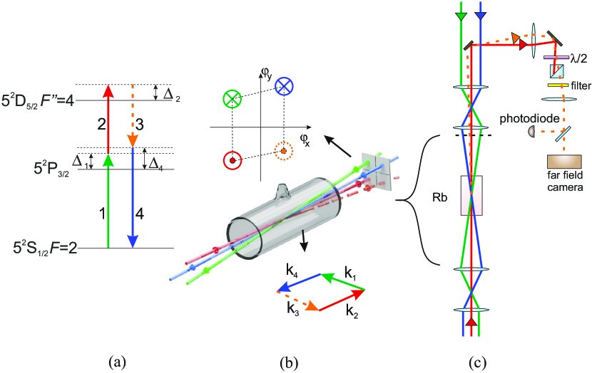
The four-wave mixing signal is generated by the nonlinear polarization created in the atomic medium by three crossing beams (see Fig. 1(a)). We consider a general situation where three incident, non-degenerate collimated beams (No. 1, 2 and 4) generate a new signal field (beam 3). As presented in Fig. 1(a) the fields are arranged in the double-ladder configuration being nearly-resonant to atomic transitions. Beams 1 and 2 take part in two-photon absorption. Beams 3 and 4 take part in two-photon emission, where beam 4 stimulates the emission of the four-wave mixing signal (beam 3).
To facilitate theoretical description of the process, let us first consider propagation of a monochromatic signal in a nonlinear atomic medium with polarization . Approximate equation for the electric field envelope of this signal has the following well-known form (see [18]):
| (1) |
where , is the linear polarizability, is emitted light frequency and . In the transverse Fourier domain () the equation takes on the following form:
| (2) |
where we have used the exponential ansatz for rapidly-varying longitudinal phase dependance and tilde indicates the Fourier transform of a respective field. In the experiment we start with no four-wave mixing signal at the input , so the above equation may be integrated to yield the signal field amplitude at the exit of the atomic medium:
| (3) |
High macroscopic amplitude at the output is generated only when the spatial oscillations in -direction inside the integral are slow in comparison with the medium length , and thus the correct phase matching is required.
The incoming laser beams indexed by are assumed to be Gaussian with equal diameters of . Their frequencies determine their wavevector lengths , with being the refractive index for respective beam. They propagate at small angles with respect to the -axis, so it is convenient to replace wavevectors with angles , . The desired final result is the angular distribution of emitted four-wave mixing signal and its total intensity Let us assume that the amplitude of incident beam is maximal along the -axis, neglecting shifts of beams centers:
| (4) |
Corresponding nonlinear atomic polarization generated in such a system is:
| (5) |
where and the resulting polarization wavevector This wavevector is oriented at an angle to the -axis, so transverse coordinates are given by
| (6) |
Inserting the expression for nonlinear polarization [Eq. (5)] with the wavevector given by Eq. (6) to the integral [Eq. (3)], we obtain the final distribution of the four-wave mixing signal:
| (7) |
| (8) |
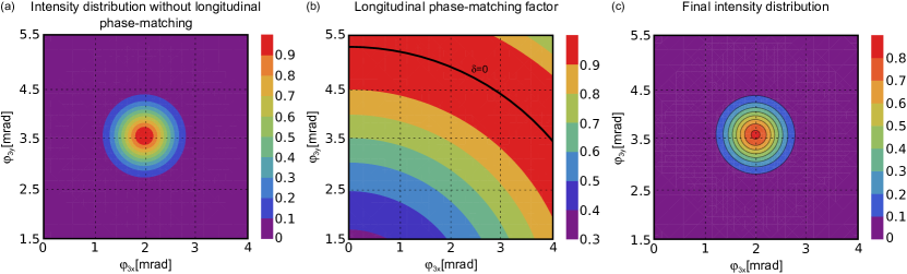
The above formula for the distribution consists of two factors: (a) the Gaussian factor that depends only on transverse variables and is the result which is obtained if we neglect the longitudinal phase matching and (b) the factor that represents the longitudinal phase-mismatch. Fig. 2 shows example theoretical intensity distribution of emitted beam without taking into account the longitudinal phase-matching condition (i.e. the Gaussian factor, at the left) and the ring-shaped phase-matching factor (at the right). Shape of the four-wave mixing intensity distribution depends on angles and wavevector lengths of incoming beams. The Gaussian factor is virtually independent of frequencies. Indeed, small changes of wavevector lengths shift the Gaussian factor by much less than its width , so they can be neglected. However, since , we need very small [see Eq. (8)] for efficient phase matching. Equation (8) can be rewritten as which for describes the cone of perfect phase matching. In the transverse plane, the best phase-matching is achieved on the ring with radius with angular width of approximately
| (9) |
We now consider changes of the radius as a function of incident and emitted beams wavevectors. The derivative over is
| (10) |
A typical value we find for in the experiment is of the order of rad, so derivative is of the order of m-1. Therefore, change of refractive index of the order of causes change of of the order of rad, much more than phase-matching ring width. By analogy we can calculate the derivative over incident beam angles :
| (11) |
Consequently, unless the spatial configuration is properly designed, the overlap between phase-matching ring and Gaussian factor from Eq. (7) could potentially decrease with any change of and resulting change of the phase-matching ring radius .
We now consider linear and nonlinear polarizabilities essential to description of the four-wave mixing process. The third order polarizability can be obtained through perturbation chain for a specific case we consider in the experiment [8]:
| (12) |
where , is the decay rate, are dipole moments of transitions between respective states and is the atomic concentration. Additionally, since phase matching plays a crucial role, we take into account dispersion of refractive index. The linear polarizability for beam 1 is:
| (13) |
where is the Rabi frequency for beam 2. The linear polarizability for beam 4 takes on analogous form. For beam 2 we have the following linear polarizability:
| (14) |
and the polarizability for beam 3 will take on an analogous form as well.
To complete our considerations we take the Doppler broadening into account. All, linear and nonlinear, polarizabilities should be averaged over the Maxwell velocity distribution [8, 25]:
| (15) |
| (16) |
where is the atomic mass, is Boltzmann’s constant and is temperature. Dominant contribution of the Doppler broadening is present in single-photon terms, which we take into account as full Voigt profiles in the above calculation. However, there is also residual Doppler broadening in the two-photon terms with . Since calculation of this term is time-consuming while the broadening is small, we decided to replace it by additional natural broadening, which is of quite different shape, but gives similar and consistent results.
Originally our model is created for four-wave mixing in double-ladder configuration, but it is worth to mention that it can be very easily adapted to another schemes like diamond or double- configuration and other multi-wave mixing schemes. We only need to change the polarizabilities, which in any case have analogous forms. The model is also applicable to the cylindrically-symmetric case, where all beams are co-propagating. Instead of radial shift of emission direction one could observe emission to the cone where the apex angle depends on detunings. This regime can be reached if we use beams with sufficiently small diameters .
In following sections we describe measurements of four-wave mixing signal characteristics (intensity and direction of emission) as a function of detunings and direction of all incoming beams and we compare it with theoretical prediction of model presented above.
3 Experimental
Essential components and ideas of the experiment are presented in Fig. 1. We use a double-ladder level configuration in 87Rb [Fig. 1(a)]. The four-wave mixing signal is generated on the transition between and manifolds. To drive the process we use three lasers: one external-cavity diode laser (ECDL, number 2) with wavelength of 776 nm and linewidth approx. 100 kHz and two distributed feedback (DFB) laser diodes with wavelengths of 780 nm (number 1 and 4) and linewidth of about 1 MHz. To minimize the two-photon Doppler broadening laser beams 1 and 2 are arranged in the counter-propagating configuration. The 776 nm laser is stabilized using a commercial wavemeter (HighFinesse WS7). One of the 780 nm lasers is locked at the vicinity of two-photon absorption peak using an auxiliary rubidium vapor cell placed in a tunable magnetic field where we crossed strong circularly polarized 776 nm laser beam and weak linearly polarized laser 1 beam at 780 nm. By measuring polarization rotation in circular basis we could generate tunable locking signal, that controls laser 1 and lock the two lasers at . More details of this method are described in [26]. Using the fact that the difference between frequencies of lasers 1 and 4 is of the order of several GHz, laser 4 is stabilized by beat-note measurement.
All laser beams intersect in the cell with warm rubidium vapors at natural abundance and no buffer gas. Fig. 1(b) depicts the central part of the setup and a telescope used to obtain beams intersecting at approx. mrad angle and diameter of 400 m. To eliminate influence of external magnetic fields the cell is placed inside a double -metal shielding. Additionally, the cell is heated using a bifilarly-wound coil to avoid stray magnetic field from the heater.
The generated four-wave mixing signal is separated from stray driving light using a half-wave plate with a polarizing beamsplitter and then using a band-pass interference filter tilted to transmit light at 776 nm. The signal is registered by an avalanche photodiode (APD) or a CCD camera situated in the far field of the rubidium cell, allowing us to measure angular distribution of the emission. A flip-mirror is used to select either the APD or the CCD camera (Fig. 1 (c)).
4 Results
In the following section we compare our experimental and theoretical results to demonstrate the importance of the phase-matching condition and finally engineer the optimal geometry for the process.
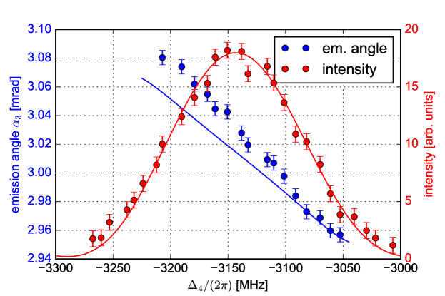
First, we observe the dependence of the average emission angle of the four-wave mixing signal on detuning , while remaining detunings are kept constant. In particular, driving beam 1 is far detuned from the resonance ( MHz), while being simultaneously kept in the two-photon resonance, i.e. , where the four-wave mixing signal is close to the optimum. From the theoretical point of view, the phase-matching ring, as described in Sec. 2, has finite width and overlaps with the Gaussian factor from Eq. (7) at either side. For that reason, the emission angle changes as a function of detuning (in this case ). In the experiment, the full signal beam profile at the far field is measured with the CCD camera and the average emission angle is inferred from the image after electronic background subtraction. In the theoretical framework this corresponds to the angle calculated as:
| (17) |
Measurement results and theoretical predictions results are presented in Fig. 3. We observe a strong correspondence between the two, which confirms that the reason of dependence between emission direction and lasers detunings is indeed dispersion and resulting change in phase matching.
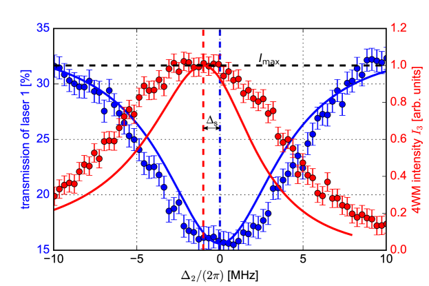
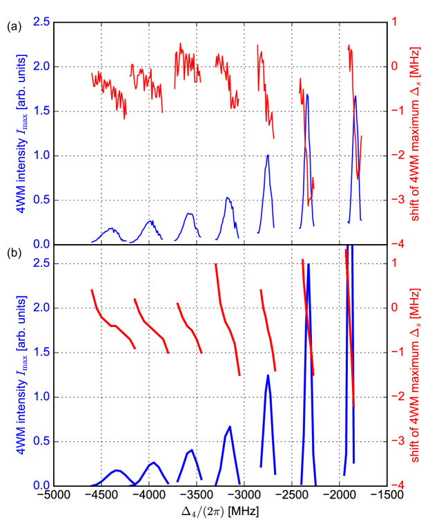
As long as the change of emission angle is perhaps the most direct consequence of dispersion and phase matching, another significant effect is the shift in optimum two-photon detuning for the four-wave mixing signal generation in relation to two-photon absorption maximum. This effect, sometimes also visible as a strong modification of spectrum, has been observed in several previous works [16, 19, 14, 6], but its origin has not been studied thoroughly. Simple theory, which neglects dispersion of refractive indices, predicts that maximum intensity of measured signal is exactly at the two-photon absorption maximum, as the third order polarizability and the two-photon absorption coefficient proportional to depends on the two-photon detuning in the very same way [see Eqs. (12) and (14)]. In all cases the magnitude of the effect is limited by the two-photon linewidth.
In our model not only large polarizability is required, but also overlap between the phase-matching ring and Gaussian factor from Eq. (7). The latter condition is not necessarily met at . From this reasoning, the frequency shift of the maximum follows. Similar situation in double- configuration was described in [24] where this effect was also presented as a consequence of dispersion. An exemplary plot of the two-photon absorption and the four-wave mixing signals as a function of the two-photon detuning are presented in Fig. 4. Note a significant shift between the extrema of the two signals, marked with dashed lines. Imperfect fit to theory is due to residual two-photon Doppler broadening, accounted for in numerical calculations as a broadened Lorentzian instead of a full Voigt profile. The shift was measured for multiple values of detunings and . Experimental results, together with theoretical prediction, are presented in Fig. 5. For different detunings the system exhibits different dispersion profiles, and thus we observe different frequency shifts . They confirm that dispersion and phase matching accurately explain dependence between the four-wave mixing signal intensity and laser detunings.
According to Eqs. (12)–(14) all polarizabilities depend linearly on the atomic concentration. In consequence not only the four-wave mixing becomes more efficient at larger atomic concentrations, but also the dispersive effects become significantly more important. As the atomic concentration strongly depends on cell temperature, the size of the measured effect will strongly depend on temperature as well, as in e.g [19]. In our experiments we set the temperature to 145 ∘C, which corresponds to the atomic concentration of the order of . This setting allows us to attain large signal intensities together with clearly visible dispersive effects.
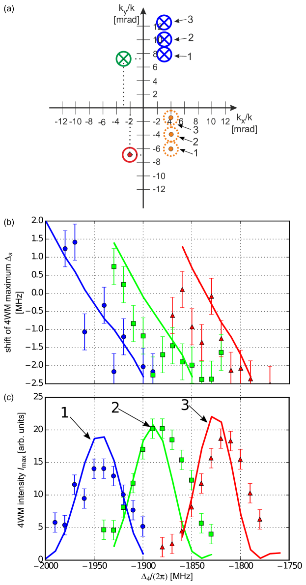
Finally, we confirm that as originally intended the geometry of the experiment may be changed to tailor the four-wave mixing signal properties. From theory it follows that the overlap between the phase-matching ring and the Gaussian factor decreases with any change of incident beams tilts , and [see Eq. (11)]. However, this overlap can be fixed by adjusting detunings. As an example, we study how the maximum of the four-wave mixing signal changes as a function of detuning if we tilt the incident beam 3. We performed the measurement for three different tilts presented in Fig. 6(a). Figures 6(b) and 6(c) portray obtained experimental and theoretical results for the frequency shift and maximum intensity , respectively. We observe that the maximum of the four-wave mixing signal changes quite significantly. Note, that without taking into account the phase-matching condition we only obtain dependance for the field amplitude [as in Eq. 12], which would clearly give a completely incorrect theoretical prediction in this case. Instead, the proper choice of geometry is critical when laser 4 is tuned closer or further from its respective single-photon resonance. These results demonstrate that our theoretical model may be used to precisely predict the behavior of the four-wave mixing signal, explaining a variety of intricacies. In particular, we may predict the optimum geometry for a desired set of detunings, or vice-versa.
5 Conclusions
We have shown that a simple model of four-wave mixing in an atomic medium that neglects propagation effects could be easily extended by considering propagation equation with nonlinear polarization to account for phase matching. In the spatial Fourier domain, the phase-matching condition implies that only some component wavevectors of the drive beams lead to effective wave-mixing. Moreover, due to dispersion, the phase-matching conditions strongly depend on laser detunings. This approach allowed us to explain some phenomena which were unexplainable earlier, like the frequency shift of the four-wave mixing signal maximum in relation to two-photon absorption maximum [16, 19, 14, 6]. The most direct consequence of dispersion seems to be the change of the four-wave mixing signal emission angle as a function of laser detunings.
These results show that our theoretical description is much more robust than an atomic model neglecting the influence of dispersion on phase matching in atomic medium and allows precise predictions of the four-wave mixing signal behavior. Moreover, we have shown that our model facilitates proper choice of geometry and consequently stronger signal may be obtained. Apart from providing a recipe for engineering of effective interaction, we believe that our results may also help study other subtle effects in four-wave mixing [27], where multiple shift effects might contribute to the total frequency shift.
Finally, we note that our approach is generally valid for a variety of systems - one needs to simply supply appropriate expressions for linear and nonlinear susceptibilities. In particular, effects treated in this work become even more critical in high-density ensembles, that facilitate strong light-matter interactions due to collective effects [28, 3], in waveguides that support modes with various longitudinal wavevectors [9], in cavity-enhanced processes [29] or finally in schemes that rely on phase-matching control, such as multimode quantum memories [30]. Our model is also applicable to the case of spontaneous four-wave mixing [3]: if we post-select on one of the fiber-coupled photons, we may predict the correlated emission direction. With further extensions our theory may also be used to model the full biphoton joint spectral/spatial properties.
Funding
The project was financed by the Polish Ministry of Science and Higher Education “Diamentowy Grant” Project No. DI2013 011943 and by the National Science Centre (Poland) Grants No. 2015/16/S/ST2/00424 and 2015/17/D/ST2/03471.
Acknowledgments
We acknowledge generous support of T. Stacewicz, K. Banaszek and R. Łapkiewicz as well as careful proofreading of the manuscript by M. Dąbrowski.