Transport mirages in single-molecule devices
Abstract
Molecular systems can exhibit a complex, chemically tailorable inner structure which allows for targeting of specific mechanical, electronic and optical properties. At the single-molecule level, two major complementary ways to explore these properties are molecular quantum-dot structures and scanning probes. This article outlines comprehensive principles of electron-transport spectroscopy relevant to both these approaches and presents a new, high-resolution experiment on a high-spin single-molecule junction exemplifying these principles. Such spectroscopy plays a key role in further advancing our understanding of molecular and atomic systems, in particular the relaxation of their spin. In this joint experimental and theoretical analysis, particular focus is put on the crossover between resonant regime [single-electron tunneling (SET)] and the off-resonant regime [inelastic electron (co)tunneling (IETS)]. We show that the interplay of these two processes leads to unexpected mirages of resonances not captured by either of the two pictures alone. Although this turns out to be important in a large fraction of the possible regimes of level positions and bias voltages, it has been given little attention in molecular transport studies. Combined with nonequilibrium IETS – four-electron pump-probe excitations – these mirages provide crucial information on the relaxation of spin excitations. Our encompassing physical picture is supported by a master-equation approach that goes beyond weak coupling. The present work encourages the development of a broader connection between the fields of molecular quantum-dot and scanning probe spectroscopy.
I Introduction
Both the fundamental and applied studies on transport phenomena in electronic devices of molecular dimensions have bloomed over the past decadeBartolomé, Luis, and Fernández (2014); Huang et al. (2015); Moth-Poulsen (2016); Perrin, Burzurí, and van der Zant (2015). An interesting aspect of this development is that it has increasingly hybridized the diverse fields of chemistry, nanofabrication and physics with the primary ambition of accessing properties like high spin and large exchange couplings, vibrational modes, large charging energies and long electronic/nuclear spin coherence times, subtle electronic orbital interplay, self-organisation Chen, Hong, and Huang (2012); Seeman (2003) and chirality Xie et al. (2011); Naaman and Waldeck (2015). This is rendered possible by the higher energy scales of the molecular systems —a direct consequence of their size— and their complex, chemically tailorable, inner structures which have proven to be effective in addressing, for instance, the spin-phononBurzurí et al. (2014); Franke and Pascual (2012), ShibaFranke, Schulze, and Pascual (2011); Island et al. (2016) and Kondo physicsFrisenda et al. (2015), quantum interference effectsKoole et al. (2015) and nuclear spin manipulationThiele et al. (2014).
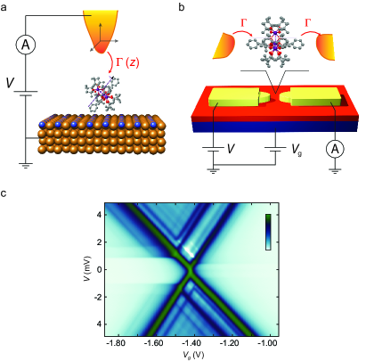
In most of the works, in particular those concerning molecular spin systems, two complementary approaches have contributed to explore these effects. On the one hand stands off-resonant transport spectroscopy, which is the major tool of choice in the scanning-tunneling microscopy (STM) approach to nanoscale spin systems Meservey and Tedrow (1994); Nussinov, Crommie, and Balatsky (2003); Heinrich et al. (2004); Meier et al. (2008); Chen et al. (2008); Wiesendanger (2009); Petukhov et al. (2009); Kahle and et al. (2012); Gauyacq, Lorente, and Novaes (2012); Ternes (2015); Burgess et al. (2015); Heinrich et al. (2015), depicted in Fig. 1(a). Off-resonant is also dominant in the field of mechanically-controlled break junctions (MCBJ)Böhler et al. (2004); Champagne, Pasupathy, and Ralph (2005) to study vibrations Chae et al. (2006); Galperin, Ratner, and Nitzan (2007); Hihath et al. (2008); Hüttel et al. (2009); Burzurí et al. (2014) and, less often, spin effectsParks et al. (2007, 2010); Frisenda et al. (2015). On the other hand, resonant transport spectroscopy, originating in the multi-terminal fabrication of quantum dots (QDs, Fig. 1(b))Hanson et al. (2007), is a well-developed tool applied to a broad range of excitations in nanostructures, Jarillo-Herrero et al. (2004); Koppens et al. (2005); Jarillo-Herrero et al. (2005); Sapmaz et al. (2005); Hüttel et al. (2005); Gräber et al. (2006); Sapmaz et al. (2006); Leturcq et al. (2009); Andergassen et al. (2010); Haupt et al. (2013) including spin.Heersche et al. (2006a); Zyazin et al. (2010); Burzurí et al. (2012); Misiorny et al. (2015); Burzurí, Gaudenzi, and van der Zant (2015); Grose et al. (2008); Kogan et al. (2003); Craig et al. (2004); Moriyama et al. (2005); Florens et al. (2011); Grove-Rasmussen et al. (2012)
| Regime | Section | QD community | STM / MCBJ community |
|---|---|---|---|
| Resonant | Sec. II.1 | Single-electron tunneling (SET) | Resonant tunneling |
| Sequential / incoherent tunneling | |||
| Off-resonant | Sec. II.2 | (In)elastic co-tunneling (COT) | (In)elastic electron tunneling spectroscopy (EETS/IETS) |
| Coherent tunneling | |||
| Schrieffer-Wolff (transformation) | Appelbaum (Hamiltonian) | ||
| Sec. II.2.1 | Pump-probe (co)tunneling spectroscopy | ||
| Crossover | Sec. II.3 | Cotunneling-assisted single-electron | |
| tunneling (COSET, CAST) |
The key difference between resonant and off-resonant approaches is the former’s reliance on energy-level control independent of the transport bias, i.e., true gating of the molecular levelsMason, Biercuk, and Marcus (2004); Biercuk et al. (2005); Hauptmann, Paaske, and Lindelof (2008); Song et al. (2009); Jespersen et al. (2011a), which should be distinguished from the capacitive level shift in STM which is caused by the bias. In terms of physical processes, this difference corresponds to resonant spectroscopy relying on “real” charging of the molecule and off-resonant transport involving only “virtual” charging.
In this contribution we discuss a comprehensive picture of transport applicable to a large family of nanoscale objects. This is motivated by the experimental spectrum of a molecular junction depicted in Fig. 1(c). Such a conductance map is so full of detail that it warrants a systematic joint experimental and theoretical study. In particular, we discuss several effects which are often overlooked despite their importance to electron transport spectroscopy and despite existing experimental Schleser et al. (2005); Hüttel et al. (2008, 2009) and theoretical works Golovach and Loss (2004); Aghassi, Hettler, and Schön (2008); Lüffe, Koch, and von Oppen (2008); Becker and Pfannkuche (2008); Weymann (2008); Leijnse and Wegewijs (2008). For instance, it turns out that “inelastic” or “off-resonant” transport is not simply equivalent to the statement that “resonant processes play no role”. In fact, we show that generally less than of the parameter regime of applied voltages that nominally qualified as “off-resonant” is actually described by the widely used inelastic (co)tunneling (COT or IETS) picture. Although in many experiments to date this has not been so apparent, our experimental evidence suggests that this needs consideration. In theoretical considerations, resonant and off-resonant transport regimes are often taken as complementary. Our measurements illustrate how this overlooks an important class of relaxation processes. The breakdown of the COT picture in the off-resonant regime presents, in fact, new opportunities for studying the relaxation of molecular spin-excitations which are of importance for applications. Interestingly, these resonances are qualitative indicators of a device of high quality, e.g., for applications involving spin-pumping. We illustrate experimentally the ambiguities that the sole modeling of off-resonant conductance curves can run into. For instance, we show that this may lead one to infer quantum states that do not correspond to real excitations, but are simply mirages of lower lying excitations, including their Zeeman splittings. Although elaborated here for a spin system, our conclusions apply generally, for example to electronic Schleser et al. (2005) and vibrational excitations in nano electro-mechanical systems (NEMS) Hüttel et al. (2008, 2009).
The outline of the paper is as follows: In Sec. II we review the physical picture of electron tunneling spectroscopy and outline how a given spectrum manifests itself in resonant [Sec. II.1] and off-resonant [Sec. II.2] transport spectra. In Sec. II.3 we discuss how these two spectra continuously transform into each other as the energy levels are varied relative to the bias voltage. With this in hand, we put together a physical picture capturing all discussed effects which will be subsequently applied to describe the experiment in Sec. III.
In Sec. III we follow the reverse path of experimental transport spectroscopy: We reconstruct the excitation spectrum of a high-spin molecular junction based on the feature-rich transport spectra as a function of bias voltage, magnetic field, and gate voltage. Starting from the off-resonant analysis, we use the boundary conditions imposed by the resonant spectrum to resolve a number of ambiguities in the off-resonant state-assignment. With the full model in hand we highlight two informative transport features: (i) nonequilibrium COT, i.e., a pump-probe spectroscopy using the electronic analog of Raman transitions and (ii) mirages of SET resonances that occur well inside the off-resonant regime. We conclude with an outlook in Sec. IV.
Since we aim to bring the insights from various communities together, we summarize in Table 1 the different but equivalent terminology used. For clarity reasons we set for the rest of this discussion.
II Physical pictures of transport - real vs. virtual charging
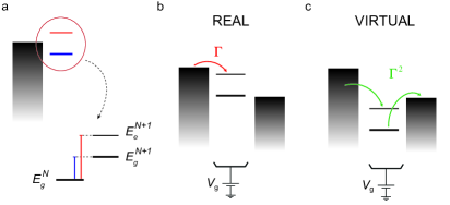
The two prevalent conceptual approaches to transport through molecular electronic devices are characterized by the simple physical distinction, sketched in Fig. 2, between “real” charging —chemical reduction or oxidation— and “virtual” charging —electrons “scattering” between contacts “through” a molecular “bridge”. Theoretically, the distinction rests on whether the physical processes appear in the leading or next-to-leading order in the tunnel coupling strength, , relative to the thermal fluctuation energy . Experimentally, this translates into distinct applied voltages under which these processes turn on. These conditions are the primary spectroscopic indicators, allowing the distinction between “real” and “virtual” transport processes, and take precedence over line shape and lifetime broadening. For reviews on theoretical approaches to molecular transport see Refs. Thijssen and van der Zant, 2008; Ferry, Goodnick, and Bird, 2009; Cuevas and Scheer, 2010; Moth-Poulsen, 2016.
II.1 Resonant transport spectroscopy
Real charging forms the starting point of what we will call the resonant picture of transport (see Table 1 for other nomenclature). Its energy resolution is limited by the Heisenberg lifetime set by the tunnel coupling
| (1) |
allowing for sharp transport spectroscopy of weakly coupled systems. This relation has a prominent place in the field of QDs which covers artificial structures as “artificial atoms” and “artificial molecules” with redox spectra Hanson et al. (2007) very similar to real atoms Tarucha et al. (2000) and simple molecules Oosterkamp et al. (1998); Maksym et al. (2000); Fujisawa et al. (2002); Moriyama et al. (2005); Gräber et al. (2006). Resonant transport also plays a role in STM although its energy resolution is often limited by the strong coupling typical of the asymmetric probe-substrate configuration.
Given sufficient weak coupling/energy resolution, much is gained when the energy-level dependence of these transport spectra, can be mapped out as function of gate-voltage. This dependence allows a detailed model to be extracted involving just a few electronic orbitals Oosterkamp et al. (1998); Begemann et al. (2008), their Coulomb interactions van der Wiel et al. (2003) and their interaction with the most relevant degrees of freedom (e.g., isotropic Grose et al. (2008) and anisotropic spins Heersche et al. (2006a); Misiorny, Weymann, and Barnaś (2009), quantized vibrations Burzurí et al. (2014); McCaskey et al. (2015), and nuclear spins Vincent et al. (2012); Ganzhorn et al. (2013); Thiele et al. (2013, 2014)). In particular electronic Cobden et al. (1998); Jarillo-Herrero et al. (2004); Biercuk et al. (2005); Jarillo-Herrero et al. (2005); Sapmaz et al. (2005); Gräber et al. (2006); Sapmaz et al. (2006); Grove-Rasmussen et al. (2012), spin-orbit Jespersen et al. (2011a, b) structure as well as electro-mechanical coupling Hüttel et al. (2009, 2008); Leturcq et al. (2009); Weber et al. (2015) of CNTs have been very accurately modeled this way.
In molecular electronics transport spectroscopy takes a prominent role since imaging of the device is challenging. By moving to molecular-scale gated structures one often compromises real-space imaging. In this paper we highlight the advantages that such structures offer. Nevertheless, electrical gates that work simultaneously with a scanning tip Piva et al. (2005) or a MCBJ Martin, van Ruitenbeek, and van der Zant have been realized, but with rather low gate coupling. Notably, mechanical gating Temirov et al. (2008); Toher et al. (2011a, b); Greuling et al. (2011a, 2013); Wagner and Temirov (2015) by lifting a single molecule from the substrate has been demonstrated, resulting in dd stability diagrams where the role of taken over by the tip-height in Fig. 1. A scanning quantum-dot Yoo et al. (1997) has also been realized using a single-molecule Wagner et al. (2015).
II.1.1 Resonant excitations - gate dependence
In the resonant transport regime one considers processes of the leading order in the tunnel coupling , cf. Eq. (1). Although most of this is in principle well-known, we review this approach Ferry, Goodnick, and Bird (2009); Bruus and Flensberg (2004) since some of its basic consequences for the off-resonant regime —discussed below— are often overlooked.
Typically, analysis of resonant spectra requires a model Hamiltonian that involves at most tens of states in the most complex situations Koch and von Oppen (2005); Koch, von Oppen, and Andreev (2006); Grose et al. (2008); Leijnse and Wegewijs (2008); Reckermann et al. (2008); Reckermann, Leijnse, and Wegewijs (2009). Its energies are labeled by the charge number and a further quantum numbers (orbital, spin, vibrational) collected into an index . Crucial for the following discussion is the voltage-dependence of this energy spectrum. We assume it is uniform, i.e., , independent of further quantum numbers . This can be derived from a capacitive description of the Coulomb interactions between system and electrodes referred to as the constant interaction model Beenakker (1991); van der Wiel et al. (2003); Bruus and Flensberg (2004); Ferry, Goodnick, and Bird (2009); Thijssen and van der Zant (2008). In this case, where are constants and () is the potential applied at source (drain) electrode. Here, for , R,g are capacitive parameters of which only two are independent since . In Sec. II.4 we discuss corrections to this —often good— assumptionKaasbjerg and Flensberg (2011). Unless stated otherwise, we will set for simplicity , i.e., the negative shift of the energy levels equals the gate voltage. The bias is applied to the electron source, , and the drain is grounded, , giving and with constant . Unless stated otherwise, schematics are drawn assuming , corresponding to symmetric and dominant source-drain capacitances .
The Hamiltonian for the complete transport situation takes the generic form where is a sum of tunneling Hamiltonians that each transfers a single electron across one of the junctions to either metal electrodes. The electrodes, labeled by L(left), R(right), are described by —essentially through their densities of states— and by their electrochemical potentials and temperature . For the present purposes this level of detail suffices, e.g., see LABEL:Leijnse_Phys.Rev.B78/2008 for details. For a tunneling process involving such a transfer of precisely one electron, one of the electrochemical potentials has to fulfill
| (2) |
in order for the electron to be injected into an -electron state , resulting in the final -electron state . Below this threshold the state is “unstable”, and decays back to by expelling the electron back into the electrode. The rate for the injection process, , is given by familiar “Golden Rule” expressions and depends on the difference of both sides of Eq. (2) relative to temperature . When the process “turns on” by changing , it gives rise to a peak in the differential conductance, dd, corresponding to a sharp step in current, of width and height (in units of ) since we are assuming weak coupling and high temperature.
If the total system conserves both the spin and its projection along some axis (e.g., the -field axis), the rate involves a selection-rule-governed prefactor. This prefactor is zero unless the change of the molecular spin and its projection satisfy
| (3) |
These conditions reflect the fact that only a single electron is available for transferring spin to the molecule.
Incidentally, we note that this picture is very useful even beyond the weak couplings and high temperatures assumed here. Close to the resonance defined by condition (2) the transport still shows a peak which is, however, modified by higher-order corrections. The width of the current step becomes broadened , giving a conductance peak in units of . Its energy position may shift on the order of .
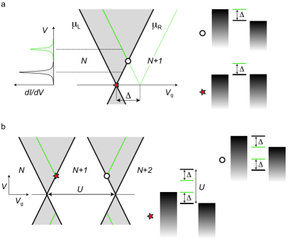
It is now clear in which regime of applied voltages the above picture applies. In Fig. 3 this is sketched in the plane of applied bias () and gate voltage (). Here, we call such a (schematic) dd intensity plot —also known as “stability diagram” or “Coulomb-diamond”— a transport spectrum. The indicated vertical line cuts through this diagram correspond to dd traces measured in STM or MCBJ experiments. Applied to the ground states of subsequent charge states —labeled by —, Eq. (2) gives the two inequalities
| (4) |
These define the shaded bias window in Fig. 3(a), delimited by the “cross”. Here, a single electron entering from the left can exit to the right, resulting in a net directed current.
It is now tempting to naively define the off-resonant regime as the complement of the grey resonant regime in Fig. 3(a), i.e., by moving across its boundaries by more than or . A key point of our paper is that this simple rationale is not correct already for a small finite bias matching some excitation at energy , indicated by green lines in Fig. 3(a). Only in the linear-response regimeBeenakker (1991) around the off-resonant regime can be defined as the complement of the resonant regime:
| (5) |
In subsequent charge states analogous considerations apply: transitions between charge states and give rise to a shifted ”copy” of the bias window as shown in Fig. 3(b). The shift —experimentally directly accessible— is denoted by:
| (6) |
This includes the charging energy of the molecule, but also the magnitude of orbital energy differences and the magnetic field.111For example, for a single orbital level with charging energy and magnetic field one finds due to the opposite spin-filling enforced by the Pauli principle.
II.1.2 Stationary state and resonant transport current
The above rules are substantiated by a simple master equation for the stationary-state occupations of the states with energy that can be derived from the outlined model, see, e.g., LABEL:Leijnse_Phys.Rev.B78/2008. This approach is used in Sec. III.3.2 to model part of our experiment. For the resonance regime the stationary-state equation reads (for notational simplicity we here set )
| (7) |
Here, is the matrix of transition rates between states and , and analogously for . For example, one of the equations,
| (8) |
describes the balance between the gain in occupation probability due to all transitions , and the leakage from the state . The entries of the diagonal matrices and have negative values and , respectively, such that probability normalization is preserved in Eq. (7). In the leading order in , the rate matrix has separate contributions from the left () and right () electrode: . These allow the stationary current to be computed by counting the electrons transferred by tunnel processes through the -th junction,
| (9) |
where stationarity guarantees . We note that, because we are considering only single-electron tunneling processes (first order in ), the primed sum is constrained to by charge conservation.
II.2 Off-resonant transport spectroscopy
We now take the opposite point of view and consider transport entirely due to “virtual charging” or “scattering through” the molecule. The resulting off-resonant transport spectroscopy, alternatively called cotunneling (COT) or IETS spectroscopy, dates back to Lambe and Jacklevic Lambe and Jaklevic (1968). The discussion of the precise conditions under which the off-resonant picture applies is postponed to Sec. II.3. Throughout we will denote by the label COT—unless stated otherwise— inelastic cotunneling.
The attractive feature of off-resonant relative to resonant spectroscopy is the higher energy resolution as we explain below [Eq. (18) ff.]. Exploiting this in combination with the STM’s imaging capability has allowed chemical identification Khajetoorians et al. (2012); Kahle and et al. (2012); Brede and Wiesendanger (2012); Khajetoorians et al. (2013); Bryant et al. (2013); Rau et al. (2014); Hapala et al. (2014); Wagner et al. (2014); Heinrich et al. (2015); Burgess et al. (2015); Wagner et al. (2015); Bazarnik et al. (2016). This in turn has enabled atomistic modeling of the junction using ab-initio calculations Hirjibehedin, Lutz, and Heinrich (2006); Hirjibehedin et al. (2007); Serrate et al. (2010); Baumann et al. (2015), also including strong interaction effects Greuling et al. (2011b); Weiss et al. (2010); Esat et al. (2015), giving a detailed picture of transport on the atomic scale Atodiresei et al. (2009); Loth et al. (2010); Khajetoorians et al. (2011); Yan et al. (2015a, b); Khajetoorians et al. (2016); Steinbrecher et al. (2016).
In recent years, off-resonant spectroscopy has been also intensively applied to spin systems Heinrich et al. (2004); Otte et al. (2008); Loth, Lutz, and Heinrich (2010); Kahle and et al. (2012); STM (2014); Ternes (2015) in more symmetric Repp et al. (2005) STM configurations. However, it is sometimes not realized that the same off-resonant spectroscopy also applies to gated molecular junction, and more generally to QDs De Franceschi et al. (2001); Zumbühl et al. (2004); Katsaros et al. (2010); Jespersen et al. (2011c). In fact, motivated by the enhanced energy resolution, spectroscopy of discrete spin-states was introduced in gate-controlled semiconductor QDs De Franceschi et al. (2001); Wegewijs and Nazarov ; Hartmann and Wilhelm (2003) before it was introduced in STM as “spin-flip” spectroscopy Heinrich et al. (2004), see also Averin and Nazarov (1990); Grabert and Devoret (1992). COT spectroscopy is also used to study molecular properties other than spin, e.g., vibrational states Stipe, Rezaei, and Ho (1998); Yu et al. (2004); Kim et al. (2011); Bürkle et al. (2013); Böhler, Edtbauer, and Scheer (2007); Herz and Scheer (2016).
II.2.1 Off-resonant excitations – no gate dependence
In the off-resonant picture, one considers transport due to next-to-leading order processes, i.e. of order in the tunnel rates. This involves elastic (inelastic) processes involving two electrons from the electrodes and a zero (net) energy transfer of energy. When the maximal energy supplied by the electrons —one electron coming in from, say, at high energy , and the other outgoing to at low energy — exceeds a discrete energy difference of the molecule,
| (10) |
transport may be altered with . Importantly, on the right hand side, all and dependences of the energies cancel out [cf. Sec. II.1.1] since we assumed that the applied voltages uniformly shift the excitation spectrum for fixed charge.Kaasbjerg and Flensberg (2011); Perrin et al. (2013)
The occurrence of such a process depends on whether the initial state is occupied or not by another already active process. It thus depends on whether we are in the “equilibrium” or “nonequilibrium” regime, both of which are accessible in our experiment in Sec. III. The spectroscopy rules require the following separate discussion.
“Equilibrium” inelastic COT—
Already in the linear transport regime, 222(assuming no excitations lie below and ), there is scattering through the molecule in a fixed stable charge state in the form of elastic COT Averin and Nazarov (1990); Grabert and Devoret (1992); König, Schoeller, and Schön (1997), see Table 1 for the varied nomenclature. This gives rise to a small current scaling . With increasing bias , this mechanism yields a nonlinear background current which is, however, featureless.
When the voltage provides enough energy to reach the lowest excitation of the -electron ground state , the transition is enabled, cf. Fig. 2(c). This occurs when the gate-voltage independent criterion set by Eq. (10) with and is satisfied:
| (11) |
The above energy condition is the tell-tale sign of an off-resonant process: as sketched in Fig. 4(a), this allows for a clear-cut distinction from resonant processes with a gate dependent energy condition (2). Importantly, such a COT feature always connects to the gate-dependent SET resonance corresponding to excitation . As in the resonant regime, we stress that criterion (11) uses the peak position in the ( plane as a primary indicator. The line shape along a vertical cut in the figure, as measured in STM, may be less clear. In theoretical modeling the line shape is also not a unique indicator. The line shape is a good secondary indicator of the nature of a process.
“Nonequilibrium” inelastic COT: electronic pump-probe spectroscopy.—
The above “equilibrium” picture of off-resonant transport has been successfully applied in many instances. However, as the first excited state is accessed, the rules of the game change. If the relaxation induced by sources other than transport is weak enough Schmaus et al. (2009), the occupation of the excited states can become non-negligible. In such a case, as illustrated in Fig. 4(b), a secondary inelastic COT process from the excited state to an even higher excited state should be considered. Such secondary processes, with the generic condition:
| (12) |
indicate a device with an intrinsic relaxation rate small compared to COT rates . As discussed in Fig. 4(b), such excitations never connect to a corresponding SET excitation in the transport spectrum. At this point, two cases have to be considered, both of which are relevant to the our experiment in Sec. III.4.
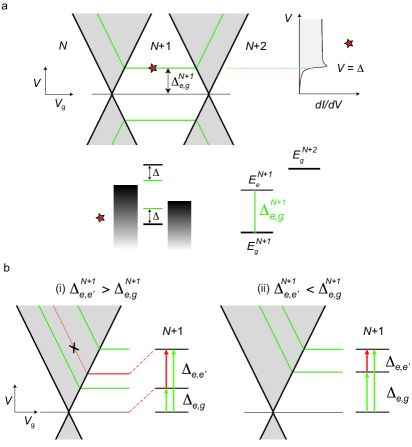
(i) If —i.e., the gaps in the energy spectrum grow with energy— an extra ”nonequilibrium” inelastic COT resonance at bias appears, as illustrated in panel (i) of Fig. 4(b). This extra resonance is very useful since it provides a further consistency check on the excitations and observed independently in the SET.333(If the SET transition to is not allowed by a selection rule, the secondary COT resonance may be the only evidence of this state.) Clearly, the intensity of such secondary ”nonequilibrium” COT resonances is generally expected to be lower than the primary ones that start from the ground state. In Sec. III.4 we will experimentally control this sequential COT “electronic pump-probe” excitations by tuning a magnetic field.
(ii) In the opposite case, , no extra COT excitation related to appears: there is no change in the current at the lower voltage because the initial state only becomes occupied at the higher voltage . This is illustrated in panel (ii) of Fig. 4(b). Examples of both these cases occur in the off-resonant spectra of molecular magnets due to the interesting interplay of their easy-axis and transverse anisotropy, see the supplement of LABEL:Zyazin_NanoLett.10/2010.
II.2.2 Stationary state and off-resonant transport current
Similar to the resonant case, the conditions (10)-(12) are incorporated in a simple stationary master equation for off-resonant transport whose derivation we discuss further below. In particular, the occupation probabilities in the stationary transport state are determined by (as previously, we put )
| (13) |
Here, is a matrix of rates for transitions between states . Since in the off-resonant regime charging is only “virtual”, these transitions now occur for a fixed charge state. The matrix takes the form , including rate matrices for back-scattering from the molecule (to the same electrode, ) and scattering through it (between electrodes ). The current is obtained by counting the net number of electrons transferred from one electrode to the other:
| (14) |
The inclusion into this picture of the above discussed “non-equilibrium” COT effects depends whether one solves the master equation (13) or not. To obtain the simpler description of “equilibrium” inelastic COT [case (i) above] one can insert by hand equilibrium populations directly into Eq. (14). Solving, instead, Eq. (13) without further assumptions gives the “nonequilibrium” inelastic COT case Paaske et al. (2006); Ternes (2015) discussed above [case (ii)]. In practice, these two extreme limits —both computable without explicit consideration of intrinsic relaxation— are always useful to compare since any more detailed modeling of the intrinsic relaxation will lie somewhere in between’.
The electron tunneling rates in Eq. (13) are made up entirely of contributions of order . There are two common ways of computing these rates, and we now present the underlying physics relevant for the discussion in Sec. II.3.
Appelbaum-Schrieffer-Wolff Hamiltonian.—
A conceptual connection between the off-resonant “virtual” charging picture and the resonant picture of “real” charging in Sec. II.1 emerges naturally when applying the unitary transformation Wagner (1986) due to Appelbaum Appelbaum (1966, 1967), Schrieffer and Wolff Schrieffer and Wolff (1966); Schrieffer (1967); Bravyi, DiVincenzo, and Loss (2011) (ASW) to the transport Hamiltonian [cf. Sec. II.1]. The effective ASW model obtained in this way allows one to easily see the key features of the off-resonant spectroscopy.
In this approach, the one-electron tunneling processes described by the Hamiltonian , are transformed away and the charge state is fixed by hand to a definite integer. With that, also all the gate-voltage dependence of resonance positions [Eq. (11) ff.] drops out. This new ASW model is obtained by applying a specially chosen unitary transformation to the original Hamiltonian such that:
| (15) |
The term is effectively replaced by , which involves only processes and represents exclusively scattering of electrons “off” and “through” the molecule. In many cases of interest Ternes (2015) this coupling contains terms describing the potential (scalar) and exchange (spin-spin) scattering of electrons and holes with amplitudes and , respectively:
| (16) |
In the equation above, the operators () describe spin-(in)dependent intra- [] and inter-electrode [] scattering of electrons, see LABEL:Bruus_book for details. This scattering is coupled to the molecule through its charge (, constant) and spin ().
Selection rules. The ASW coupling has selection rules that differ from the original single-electron tunnel coupling :
| (17) |
These reflect that the two electrons involved in the scattering process have integer spin 0 or 1 available for exchange with the molecule. We will apply this in Sec. III.1. This is illustrated by the example model (16) where the spin-operator has matrix elements that obey Eq. (17).
Lifetime. After transforming to this new effective picture, scattering becomes the leading order transport mechanism. The “Golden Rule” approach can be then applied analogously to the case of of the resonant regime, but now with respect to the ASW scattering . In this way Eq. (13) is obtained together with an expression for the corresponding rate matrix . The dd given by Eq. (14) shows gate-voltage-independent steps at energies set by Eq. (10).
Although at high temperatures these steps get thermally broadened Lambe and Jaklevic (1968), at low enough their broadening is smaller than that of the SET peaks. While calculation of this lineshape requires higher-order contributions to , the relevant energy scale (inverse lifetime) is given by the magnitude of the “Golden Rule” rates for the effective coupling scaling as
| (18) |
This results in a much larger lifetime compared to the one from SET [cf. Eq. (1)] due to the role of the interactions on the molecule suppressing charge fluctuations. The smaller intrinsic broadening is a key advantage of COT vs. SET spectroscopy De Franceschi et al. (2001).
Line shape. Due to nonequilibrium effects —i.e., the voltage-dependence of the occupations obtained by solving Eq. (13)— a small peak can develop on top of the COT step Wegewijs and Nazarov ; Hartmann and Wilhelm (2003); Paaske et al. (2006); Sothmann and König (2010). Moreover, processes beyond the leading-order in , which is all the COT approach accounts for, can have a similar effect. These turn the off-resonant tunneling step into a dd peak and are in use for more precise modeling of experiments Hurley, Baadji, and Sanvito ; Hurley, Baadji, and Sanvito (2012); Ternes (2015). Spin-polarization Schweflinghaus et al. (2014) and spin-orbit effects Katsaros et al. (2010); Hurley, Baadji, and Sanvito (2012), however, also affect the peak shape and asymmetry.
At low temperatures and sufficiently strong coupling a nonequilibrium Kondo effect develops which has been studied in great detail Rosch et al. (2003); Paaske, Rosch, and Wölfle (2004); Paaske et al. (2006); Schoeller and Reininghaus (2009); Saptsov and Wegewijs (2012). These works show that the peak amplitude is then enhanced nonperturbatively in the tunnel coupling, in particular for low lying excitations. This requires nonequilibrium renormalization group methods beyond the present scope and we refer to various reviews Aleiner, Brouwer, and Glazman (2002); Pustilnik and Glazman (2004); Glazman and Pustilnik (2005); Schoeller (2009); Fritsch and Kehrein (2009); Eckel et al. (2010). In particular, it requires an account of the competition between the Kondo effect and the current-induced decoherence Paaske et al. (2004) in the (generalized) quantum master equation for the nonequilibrium density operator Schoeller and Reininghaus (2009); Saptsov and Wegewijs (2012).
From the present point of view of spectroscopy, the Kondo effect can be considered as a limit of an inelastic COT feature at as , see Fig. 4(a). Its position is simply at gate voltages sufficiently far between adjacent SET resonances by criterion (5). In particular, for transport spectroscopy of atomic and molecular spin systems the Kondo effect and its splitting into COT features Heersche et al. (2006b); Scott and Natelson (2010); Komeda et al. (2011); Frisenda et al. (2015) is very important especially in combination with strong magnetic anisotropy Romeike et al. (2006); Leuenberger and Mucciolo (2006); Romeike et al. (2011); Wegewijs et al. (2011); Žitko, Peters, and Pruschke (2008, 2009); Fernández-Rossier (2009); Žitko and Pruschke (2010); Elste and Timm (2010); Misiorny, Weymann, and Barnaś (2011a, b); Delgado and Fernández-Rossier (2011); Misiorny and Weymann (2014). We refer to reviews on STM Ternes, Heinrich, and Schneider (2009); Brune and Gambardella (2009); Gauyacq, Lorente, and Novaes (2012); Lounis et al. (2014) and QD Florens et al. (2011) studies.
“Golden Rule” -matrix rates.—
A second way of arriving at the master equation (13) and the rates in is the so-called -matrix approach. In essence, here COT is regarded as a scattering process: in the “Golden Rule” the next-to-leading order -matrix Bruus and Flensberg (2004),
| (19) |
is used instead of the coupling , where is the scattering energy. The main shortcoming of this approach is that the -matrix rates so obtained are infinite. The precise origin of the divergences was identified in LABEL:Koller_Phys.Rev.B82/2010 to the neglect of contributions that formally appear in first-order in but which effectively contribute only in second order to the stationary state Leijnse and Wegewijs (2008). 444These come from so-called secular contributions, involving off-diagonal elements of the density matrix in the energy basis, in addition to the diagonal elements, the probabilities. By taking these contributions consistently into account Koller et al. (2010), finite effective ratesfoo (a) for the master equation for the probabilities are obtained. In both the ASW and -matrix approach these contributions are ignored and, instead, finite expressions for the rates are obtained only after ad-hoc infinite subtractions Turek and Matveev (2002); Koch, von Oppen, and Andreev (2006). This regularization “by hand” can —and in practice does— lead to rates different from the consistently-computed finite rates, see LABEL:Koller_Phys.Rev.B82/2010,Begemann10 for explicit comparisons. These problems have also been related Timm (2008) to the fact that calculation of stationary transport using a density matrix (occupations) is not a scattering problem —although it can be connected to it Timm (2011)— in the following sense: the coupling to the electrodes is never adiabatically turned off at large times (i.e., there is no free “outgoing state”).
As we discuss next, such a consistent first plus second order approach is not only technically crucial but this also leads to additional physical effects that we measure in Sec. III.
II.3 Resonant– off-resonant crossover
Having reviewed the two prominent, complementary pictures of transport due to “real” and “virtual” charging, we now turn to the crossover regime where these two pictures coexist. This has received relatively little attention, but our experiment in Sec. III highlights its importance. As we have seen, despite the fact that charging is only “virtual”, an energy exchange between molecule and scattering electrons can occur. Depending on the energy-level positions, this “virtual” tunneling can “heat” the molecule so as to switch on “real” charging processes even well outside the resonant regime. However, in contrast to real heating, which leads to smearing of transport features, this nonequilibrium effect actually results in sharp features in the transport as a function of bias voltage. It thus becomes a new tool for spectroscopy.
II.3.1 SET mirages of COT excitations
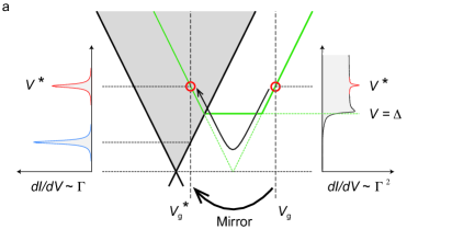
We first consider the simple case of a single excited state at energy for electrons. In Fig. 5(a) we see that the resulting COT resonance at (red) connects to the excited-state SET resonance (blue), see also Fig. 4(a). The other SET resonance condition for the excited state,
| (20) |
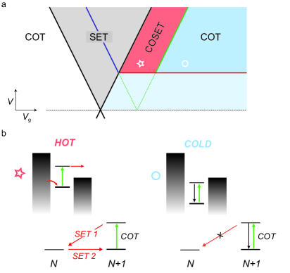
defines the green line dividing the inelastic COT regime into two regions shaded red and blue. In the one shaded blue, at the point marked with a circle, the excited state created by a COT process is stable, that is, it cannot decay by a single-electron process since . As shown in the right panel of Fig. 5(b), the relaxation of this stable state can then only proceed by another COT process —via “virtual” charging— and it is thus slow (). Essentially, this means that the molecule is not “hot” enough to lift the Coulomb blockade of the excited state.
In contrast, in the red shaded area, at the point marked with a star, this stability is lost as . Now the relaxation proceeds much faster through a single-electron process (order ) as sketched in the left panel of Fig. 5(b). The molecule gets charged for “real” (either or ) and quickly absorbs / emits an electron returning to the stable electron ground state, where the system idles waiting for the next COT excitation. Notably, this quenching of the excited state takes place far away from the resonant transport regime in terms of the resonance width, i.e., violating the linear-response criterion (5) for being “off-resonance”.
The enhanced relaxation induced by first-order tunneling, occurring when moving from the circle to the star in Fig. 5(a), leads to a change in current if no other processes (e.g., phonons, hyperfine coupling, etc.) dominate this relaxation channel (). As a results, the presence of such a resonance signals a “good” molecular device, i.e., one in which the intrinsic relaxation is small compared to the “transport-coupling” . We refer to this resonance, first pointed out in Refs. De Franceschi et al., 2001; Wegewijs and Nazarov, ; Golovach and Loss, 2004 and studied further Schleser et al. (2005); Aghassi, Hettler, and Schön (2008); Becker and Pfannkuche (2008); Weymann (2008); Leijnse and Wegewijs (2008), as cotunneling-assisted SET or COSET.
The COSET resonance has both COT and SET character. On the one hand, the geometric construction in Fig. 5(a) and Fig. 6 shows that it stems from the same excitation as the COT step at . However, its position has the same strongly gate-voltage dependence as a SET resonance, in contrast to the original COT resonance at . Yet, the COSET peak requires COT to appear and its amplitude is relatively weak, whereas the SET peak is strong and does not require COT. For this reason, the COSET peak can be seen as a “mirage” of the COT excitation and a “mirror image” of the SET peak, as constructed in Fig. 6(a). The resulting mirrored energy conditions can easily be checked in an experiment —cf. Fig. 14— and impose constraints on spectroscopic analysis: if dd shows a resonance as a function of bias outside the SET regime, a resonance at the mirrored position inside the SET regime should be present.
II.3.2 Connecting off-resonant and resonant analyses
Besides the appearance of COSET mirages, the crossover regime provides further important pieces of spectroscopic information by constraining how SET and COT spectra continuously connect as the gate voltage is varied. This is discussed in Sec. II.1.2, II.2 and later on in Sec. III.3.2, but we summarize the rules here. First, only “equilibrium” COT transitions —the only ones connecting to an SET resonance as we explained in Fig. 5— can exhibit a COSET mirage. Second, excited-excited COT transitions (i.e., for the same charge state ) never connect to a corresponding SET feature, as we illustrated in panel (i) of Fig. 4(b). Finally, transitions between excited states with different charge —visible in the SET regime— never connect to a COT feature as will be illustrated in Fig. 12. These are strict consistency requirements when analyzing the transport spectra in the SET-COT crossover regime.
II.3.3 When is transport “off-resonant” ?
We are now in the position to determine the region in which the physical picture of off-resonant scattering through the molecule of Sec. II.2 applies. This is illustrated in Fig. 7.
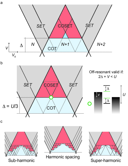
The key necessary assumption of the COT approach —often not stated precisely— is that all excited states that are accessible from the ground state must be “stable” with respect to first-order relaxation processes:
| (21) |
This is the case if the SET condition (2) additionally holds for the excited states, i.e., for in Eq. (2):
| (22) |
for both . We note that in theoretical considerations, it is easy to lose sight of condition (22) when “writing down” an ASW Hamiltonian model (or only -matrix rates for COT) [Sec. II.2.2] and assuming the couplings to be fitting parameters of the theory.555(In fact, one has to add to condition (22) that “accessible” means also accessible via nonequilibrium cascades of COT transitions (“nonequilibrium COT”), but we will not discuss this further complication.)
In Fig. 5(a) we already shaded in light blue the region bounded by the first condition (22) where the COT picture applies. In Fig. 7(a) we now show that the full restrictions imposed by both “virtual” charge states and in (22) strongly restrict the validity regime of the COT approach for states with “real” occupations and charge . In Fig. 7(b) and its caption we explain that for any individual excitation the off-resonant picture always breaks down in the sense that it works only for elastic COT, i.e., for . This amounts to of the nominal off-resonant regime.
When accounting for several excited states below the threshold , a sizeable fraction of this region must be further excluded. In Fig. 7(c) we construct the regime of validity (blue) for some example situations. The shape and size of this validity regime (light blue) depends on the details of the excitation spectrum. The center panel illustrates that for a harmonic spectrum the COT picture in fact applies in only of the nominal off-resonant regime (i.e., obtained by taking the complement of the resonant regime). The left and right panel in Fig. 7(c) show how this changes for anharmonic spectra characteristic of quantum spins with positive and negative magnetic anisotropy, respectively.
In summary, resonant processes always dominate the relaxation of excitations at energy populated by off-resonant excitation because they are “too hot”: for such excitations there is no “deep” or “far off-resonant” regime where considerations based on the COT picture alone are valid. For lower-energy excitations, , there is a triangular-shaped region in which one is still truly “far off resonance” and excitations are not quenched. The size of that region varies according to (22) and is much smaller than naively expected by extending the linear-response criterion (5). Although theoretical Golovach and Loss (2004); Aghassi, Hettler, and Schön (2008); Becker and Pfannkuche (2008); Weymann (2008); Leijnse and Wegewijs (2008); Lüffe, Koch, and von Oppen (2008) and experimental De Franceschi et al. (2001); Schleser et al. (2005) studies on COSET exist, this point seems to have been often overlooked and is worth emphasizing. Experimentally, to be sure that the off-resonant picture applies to unidentified excitation one must at least have an estimate of the gap and of the level position or, preferably, a map of the dependence of transport on the level position independent of the bias as in gated experiment discussed in Sec. III or STM situations allowing for mechanical gating Temirov et al. (2008); Toher et al. (2011a, b); Greuling et al. (2011a, 2013); Wagner and Temirov (2015).
II.3.4 Stationary state and current at the resonant-off-resonant crossover
Due to their hybrid character, COSET mirages do not emerge in a picture of either “real” or “virtual” charging alone. In particular, SET processes are omitted when deriving the COT rates by means of the ASW transformation [Sec. II.2], and, for this reason, that picture cannot account for these phenomena. Instead, a way to capture these effects is to extend Eqs. (7) and (13) to a master equation which simultaneously includes transition rates of leading () and next-to-leading order (). This has been done using the -matrix approach Turek and Matveev (2002); Koch, von Oppen, and Andreev (2006), requiring the ad-hoc regularization by hand mentioned in Sec. II.2.2. A systematic expansion which avoids these problems is, however, well-known König et al. (1996); König, Schoeller, and Schön (1997, 1998). and we refer to Refs. Leijnse and Wegewijs, 2008; Koller et al., 2010; Gergs et al., for calculation of the rates.
Relevant to our experiment in Sec. III is that with the computed rates in hand, a stationary master equation needs to be solved to obtain the occupation of the states and from these the current. We stress that even when far off-resonance —where naively speaking “the charge is fixed” to, say, — a description of the transport requires a model which also includes both the and charge states, together with their relative excitations. This is essential to correctly account for the relaxation mechanisms that visit these states “for real” and not “virtual”. 666Note that keeping these states is not related to obtaining the correct strength of the couplings for scattering in the ASW Hamiltonian. Even with the correct values for and in Eq. (16), the COSET mirages are missed since only accounts for scattering processes. The minimal master equation required for off-resonant transport thus takes then the form:
| (23) |
where as before for simplicity. Here the rates for the various processes change whenever one of the energetic conditions (2) and (10) is satisfied. Examination of the various contributions in the expression of the rate matrices Leijnse and Wegewijs (2008) reveals that the following effects are included:
-
•
is a matrix of SET rates that change when condition (2) is met. It also includes -corrections that shift and broaden the SET resonance.
-
•
is matrix of both SET and COT rates. The latter change when condition (10) is met.
-
•
and are matrices of pair-tunneling rates, e.g., for transitions between states differing by two electrons, . These lead to special resonances discussed in Sec. II.4.
The solution of the full stationary master equation (23) requires some care Leijnse and Wegewijs (2008); Koller et al. (2010) due to the fact that it contains both small COT rates and large SET rates whose interplay produces the COSET mirages. Even though the (first-order) SET rates are large, they have a small —albeit non-negligible— effect since, in the stationary situation, the initial states for these transitions may have only small occupations. These occupations, in turn, depend on the competition between all processes / rates in the stationary limit. This is the principal reason why one cannot avoid solving the master equation (23) with both first and second order processes included.
To conclude, Eq. (23) captures the delicate interplay of resonant (SET) and off-resonant (COT) processes leading to mirages (COSET). The appearance of such mirages indicates that intrinsic relaxation rates are smaller than SET transport rates (). “Nonequilibrium” COT is also included in this approach and the appearance of its additional features in our experiment signals a molecular device with even lower intrinsic relaxation rates, i.e., smaller than the COT relaxation rates ().
II.4 Breaking the rules of transport spectroscopy
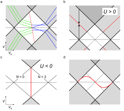
The above account of the basic rules of transport spectroscopy, although extensive, is by no means exhaustive. The key conditions are Eq. (2) and (10), determining the resonance positions as a function of applied voltages. Readers interested mostly in the application of these rules to a high-resolution transport experiment can skip the remainder of this section and proceed directly to Sec. III. Here, we give an overview of a variety of additional effects that bend or break these rules, found in experimental and theoretical studies. In Fig. 8 we sketch a number of transport spectra that cannot be understood from what we have learned in the previous discussion.
Nonuniform level shifts due to voltages.—
The assumption made so far [Sec. II.1.1] that all energy levels are uniformly shifted by applied gate and bias voltages may not be valid in case of local electric field gradients. In fact, this was already seen in the first experiment on gated COT spectroscopy of a single-triplet semiconductor dot De Franceschi et al. (2001) due to the change of the confining potential with gate voltage. In molecular junctions this has also been observed. Figure 8(a) schematizes how the transport spectrum in Refs. Osorio et al., 2010 displays such effects. In this case, the COT resonances can still be identified as weakly gate-dependent resonances, which is not a trivial issue as the experiments in LABEL:Eliasen_Phys.Rev.B81/2010 show. However, a qualitatively new and strongly gate-dependent resonanceOsorio et al. (2010); Stevanato et al. (2012) (red line) appears upon ground state change. Piecing together all the evidence, it was shown that this effect originates from a change in amplitude of the COT background, without requiring the introduction of any additional states into the model. These effects are included in Eq. (23), which was shown Stevanato et al. (2012) to reproduce the experimental data of LABEL:Osorio_NanoLett.10/2010 in detail.
Pair tunneling.—
In all the schematics so far we left out resonances that are caused by electron pair tunneling. These are described Leijnse and Wegewijs (2008); Leijnse, Wegewijs, and Hettler (2009) by the rates and included in the master equation (23). In Fig. 8(b) we sketch where these pair-tunneling resonances (red lines) are expected to appear: their positions are obtained by taking the bias-averaged positions of the two subsequent SET resonances. This condition follows by requiring the maximal energy of an electron pair in the electrode to match a corresponding molecular energy change. For example, for a single orbital at energy one obtains where is the charging energy. This gives a bias window in which pair tunneling can contribute to transport,
| (24) |
provided that the and / or the state is occupied. The effective charging energy for each electron is halved since the energy is available for both electrons together in a single process. Although small (comparable with COT) its distinct resonance position and shape clearly distinguish the pair-tunneling current from SET current LABEL:Leijnse_Phys.Rev.Lett.103/2009 that dominates in the resonant regime where it occurs.
Electron attraction.—
Clearly, pair tunneling effects are expected to become important if the effective interaction energy is attractive Haldane (1977); Koch, Raikh, and von Oppen (2006); Hwang, Choi, and López (2007); Koch, Raikh, and von Oppen (2006); Koch et al. (2007); Sela et al. (2008). Such attraction in fact appears in various systems. In molecular systems this is known as electrochemical “potential-inversion” Evans and Lehmann (1999). In artificial QDs a negative have been observed experimentally Cheng et al. ; Hamo et al. (2016) in transport spectra of the type sketched in Fig. 8(c), see also LABEL:Nilsson16. Interestingly, in this case the ground state has either or electrons and never since starting from the single-electron transition energies and are higher than electron-pair transition energy per electron . This is also included in the approach (23), see LABEL:Gergs17a.
“Coherence” effects.—
Finally, we turn to the assumption used in Sec. II.1.2 that the molecular state is described by “classical” occupation probabilities of the quantum states (statistical mixture). For instance, each degenerate spin multiplet is treated as an “incoherent” mixture of different spin projections (no quantum superpositions of spin-states states). Equivalently, the spin has no average polarization in the direction transverse to the quantization axis.
However, when in contact with, e.g., spin-polarized electrodes, such polarization does arise already in order . In that case one must generalize Eq. (23) to include off-diagonal density-matrix in the energy eigenbasis.777(The off-diagonal elements also came into play when going to order , see discussion in Sec. II.2.2.) In physical terms, this means that one must account for the coupled dynamics of charge, spin-vector and higher-rank spin tensors Sothmann and König (2010a); Misiorny, Hell, and Wegewijs (2013). In the SET regime, such effects can lead to a nearly 100% modulation of the transport current Braun, König, and Martinek (2004); Sothmann and König (2010b) due to quantum interference. This emphasises that König and Gefen (2001) SET—the first order approximation in — is not “incoherent” or “classical” as some of the nomenclature in Table 1 seems to imply.
Similar coherence effects can arise from orbital polarization in QDs J. König and Y. Gefen (2001); Wunsch et al. (2005); Donarini, Grifoni, and Richter (2006); Härtle and Millis (2014); Wenderoth, Bätge, and Härtle (2016) and STM configurations Donarini et al. (2012), from an interplay between spin and orbital coherence Begemann et al. (2008); Donarini, Begemann, and Grifoni (2009, 2010), or from charge superpositions of electron pairs. Finally, for high-spin systems coherence effects of tensorial character can arise. This leads to the striking effect that in contact with ferromagnets (vector polarization) they can produce a magnetic anisotropy (tensor) Baumgärtel et al. (2011); Misiorny, Hell, and Wegewijs (2013), see also related work Misiorny, Weymann, and Barnaś (2012); Oberg et al. (2014); Delgado, Hirjibehedin, and Fernández-Rossier (2014); Jacobson et al. (2015). An extension of the approach (23) also describes these effects Misiorny, Hell, and Wegewijs (2013); Hell et al. (2015).
The perhaps most striking effect of spin-coherence is depicted in Fig. 8(d): SET resonances can split for no apparent reason Baumgärtel et al. (2011) and wander off deep into the COT regime Hell et al. (2015) (red line). Depending on the junction asymmetry, this feature of coherent nonequilibrium spin dynamics can appear as a pronounced gate-voltage dependent current peak or as a feature close to the linear response regime, mimicking a Kondo resonance, see also LABEL:Wenderoth16.
III Spectroscopy of a high-spin molecule
In the second part of this paper we present feature-rich experimental transport spectra as a function of gate-voltage and magnetic field. Their analysis requires all the spectroscopic rules that we outlined in the first part of the paper. We show how the underlying Hamiltonian model can be reconstructed from the transport data, revealing an interesting high-spin quantum system with low intrinsic relaxation.
The molecule used to form the junction is a single-molecule magnet (SMM) with formula [Fe4(L)2(dpm)6] Et2O where Hdpm is 2,2,6,6- tetramethyl-heptan-3,5-dione. Here, H3L is the tripodal ligand 2-hydroxymethyl-2-phenylpropane-1,3-diol, carrying a phenyl ring Accorsi et al. (2006). After molecular quantum-dot formation, the device showed interesting isotropic high-spin behavior and the clearest signatures of COSET to date De Franceschi et al. (2001); Schleser et al. (2005) for any quantum-dot structure.888The device showed no significant anisotropy splittings of spin multiplets in transport, see discussion below. Before turning to the measurements and their analysis, we first discuss specific challenges one faces probing spin-systems using either COT or SET spectroscopy.
III.1 Principles of spin-spectroscopy.
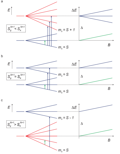
Isotropic, high-spin molecules have molecular states labeled by the spin length and spin-projection . To detect them two types of selection rules are frequently used in STM and QD studies. Using these we construct the possible spectroscopic COT and SET fingerprints that we can expect to measure.
III.1.1 Spin selection rules for COT
Spectroscopy using COT conductance as a function of magnetic field (“spin-flip spectroscopy”Heinrich et al. (2004)) has been a key tool in both STM and break-junction studies. This approach assumes that “virtual” charging processes dominate. These processes involve two electrons for which the selection rules (17) apply.
However, for high-spin molecules considered here, there can be multiple spin-spectrum assignments that fit the same COT transport spectrum. An indication for this is that in the present experiment some of the spectra are very similar to those of entirely different nanostructures Gaudenzi et al. (2016).
To see how this comes about we construct in Fig. 9(a)-(c) the three possible different fingerprints that two spin-multiplets can leave in the COT transport spectrum based on selection rules (17) alone. For simplicity, we assume that all processes start from the ground state , i.e., in the “equilibrium” situation discussed in Sec. II.2.1. This figure shows that one can determine only whether the spin value changes by 1 or remains the same upon excitation, but not on the absolute values of the spin lengths (unless the ground state has spin zero).
III.1.2 Spin selection rules for SET– spin blockade
A second key tool in the study of spin effects is the transport in the SET regime Hanson et al. (2007); Heersche et al. (2006a); Grose et al. (2008); Burzurí et al. (2012); Misiorny et al. (2015); Burzurí, Gaudenzi, and van der Zant (2015). This provides additional constraints that reduce the nonuniqueness in the COT spin-assignment.
In the SET regime, the linear-transport part is governed by the transition between the two ground-state multiplets with different charge, and , for which selection rules (3) hold. As sketched in Fig. 10, if linear SET transport is observed, then the ground-state spin values are necessarily linked by
| (25) |
This constraint, used in Refs. Zyazin et al., 2010; Osorio et al., 2007; Burzurí et al., 2012, restricts the set of level assignments inferred through COT spectroscopy on each of the two subsequent charge states, by fixing the relative ground state spins and . Their absolute values remain, however, undetermined, unless one of two happens to be zero. Arguments based on the presence of the additional spin-multiplets can then be used to motivate a definite assignment of spin values.
Molecules for which Eq. (25) fails can be identified by a clear experimental signature: the SET transport is blocked up to a finite bias as explained in Fig. 10. Such spin-blockade has been well-studied experimentally Hüttel et al. (2003); Ciorga et al. (2000); Johnson et al. (2005) and theoretically Weinmann et al. (1994); Weinmann, Häusler, and Kramer (1995); Weinmann (2003); Romeike, Wegewijs, and Schoeller (2006); Romeike et al. (2007) and finds application in spin-qubits (“Pauli-spin blockade”). It has been reported also for a molecular junction Osorio et al. (2007).
Clearly, when several excited spin multiplets/charge states are involved, both the SET and COT spin-spectroscopy become more complex. However, selection rules similar to Eq. (25) also apply to excited states and thus “lock” the two spin spectra together. In addition, the nonequilibrium occupations of the states contribute to further restrictsfoo (b) the set of possible spin-values as we will now illustrate in our experimental spectroscopic analysis.
III.2 Molecular junction fabrication
Molecular junctions are produced starting from a three-terminal solid-state device O’Neill, Osorio, and van der Zant (2007); Gaudenzi et al. (2015) consisting of an oxide-coated metallic local gate electrode with a thin gold nanowire deposited on top. On such a device, a low-concentration solution of molecules ( mM) is drop-casted. The nanowire is then electromigrated at room temperature and allowed to self-break O’Neill, Osorio, and van der Zant (2007) so that a clean nanogap is formed, with a width of nm. The solution is evaporated and the electromigrated junctions are cooled down in a dilution fridge ( mK) equipped with a vector magnet and low-noise electronics. All the measurements are performed in a two-probe scheme either by applying a DC bias and recording the current or by measuring with a standard lock-in AC modulation of the bias.
A molecular junction as sketched in Fig. 1(b) is formed when a molecule physisorbsfoo (c) on the gold leads, and thus establishes a tunneling-mediated electrical contact. The presence of the molecule in the junction is signaled by large SET transport gaps exceeding meV and low-bias inelastic COT fingerprints. Numerous molecular systems have been investigated in this configuration Heersche et al. (2006a); Osorio et al. (2010, 2007); Frisenda and van der Zant (2016); Burzurí, Gaudenzi, and van der Zant (2015); Burzurí et al. (2012); Zyazin et al. (2010); Misiorny et al. (2015); Haque et al. (2011); Henderson et al. (2007); Jo et al. (2006); Parks et al. (2010); Candini et al. (2011); Urdampilleta et al. (2011); Vincent et al. (2012); Frisenda et al. (2015); Gaudenzi et al. (2016).
As a side remark, the fact that we do not observe pronounced magnetic anisotropy effects is not unexpected: the formation of a molecular junction may involve surface interactions. In several cases previously studied clear spectroscopic signatures of the “bare” molecular structure (before junction formation), such as the magnetic anisotropy Jo et al. (2006); Zyazin et al. (2010); Parks et al. (2010), were observed also in junctions. However, depending on the mechanical and electrical robustness of the molecule, this and other spin-related parameters may undergo quantitative Burzurí, Gaudenzi, and van der Zant (2015); Misiorny and Weymann (2014); Kahle and et al. (2012); Voss et al. (2009) or qualitative changes Burgess et al. (2015); Gaudenzi et al. (2016) and sometimes offer interesting opportunities for molecular spin control Heinrich et al. (2013). Image-charge stabilization effects, for example, can lead to entirely new spin structure such as a singlet-triplet pair Osorio et al. (2007); Perrin et al. (2013) on opposite sides of a molecular bridge.
III.3 Characterization of spin states in adjacent redox states
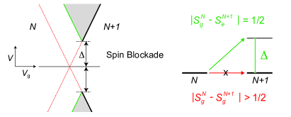
We now turn to the analysis of the feature-rich transport spectrum anticipated in Fig. 1(c) and reproduced in Fig. 11. It consists of two off-resonant regimes on the left and right with fixed charge states —provisionally labeled and — and a resonant regime in the center surrounded by a significant crossover regime.
III.3.1 Off-resonant analysis
We first separately identify the electronic spectrum for each of the two accessible charge states and using the off-resonant approach discussed in Sec. II.2.
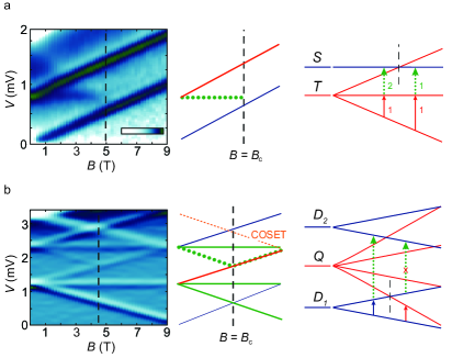
In Fig. 11 (a) we show the dd color map and the corresponding dd steps for fixed V as a function of magnetic field, . Two steps (peaks in dd) starting from meV and meV at T shift upward in energy and parallel to each other as the magnetic field increases. In the standard COT picture each step signal to the opening of an inelastic transport channel through the molecule. Transport takes place via virtual charging involving a real spin-flip excitation with selection rules on spin-length and magnetization . The charge of the molecule remains fixed, and is labeled . The shift in magnetic field of both steps indicates a nonzero spin ground state multiplet with spin . According to Sec. III.1, the presence of only one other finite-bias excitation shifting in magnetic field relates the spin-values as , but leaves their absolute values undetermined.
As we will see later, other spectroscopic information constrains the ground spin to be a triplet , , with a singlet excited state labeled . From the COT excitation voltage, a ferromagnetic (FM) interaction energy meV can be extracted. Such type of excitation has been seen in other molecular structures Osorio et al. (2007); Roch et al. (2009); Gaudenzi et al. (2016); Esat et al. (2016). Spectra of this kind have also been obtained earlier in other quantum-dot heterostructures, such as few-electron single and double quantum dots, albeit typically characterized by smaller and antiferromagnetic couplings Sasaki et al. (2000); De Franceschi et al. (2001).
We now change the gate voltage to more negative values so that the molecule is oxidized , i.e., we extract exactly one electron from the molecule. This can be inferred from the SET transport regime that we traverse along the way. In this new charge state we perform an independent off-resonant spectroscopy. In Fig. 11(b) we show the dd for V as a function of the magnetic field with corresponding dd line cuts. At T two sets of peaks in dd appear at meV and meV and split each in three peaks at higher magnetic fields. A weak excitation shifting upwards in from V is also present. With the help of Fig. 9(a) the weak excitation and the first set of peaks are associated to , while the second set, corresponding instead to the spectrum depicted in Fig. 9(b), fixes the spin to . The crucial information provided by the clear absence of spin blockade in the intermediate SET regime eventually constrains to or according to (25). The only two spin configurations compatible with the observations are therefore: a ground doublet , an excited quartet and a second doublet or, alternatively, a ground quartet, an excited sextuplet and a quartet. As we will see in the next section, the latter can be rigorously ruled out by analyzing the SET spectrum.
The presence of the excited quartet state implies that the charge state is a three-spin system, , as sketched in the top panel of Fig. 11(b). The system with one extra electron in Fig. 11(a) is thus actually a electron system with one closed shell, as sketched in the figure. Upon extraction of an electron, the spectrum of the molecular device changes drastically, transforming from a ferromagnetic high-low spin spectrum for into a nonmonotonic low-high-low spin excitation sequence for . The spin-excitation energies extracted from the two independent COT analyses are:
| (26) |
and
| (27) |
These energy differences provide the starting point of a more atomistic modeling of the magnetic exchanges in the two charge states. We stress that for the transport spectroscopy this is not necessary and it goes beyond the present scope. We only note that while the state requires only one fixed ferromagnetic exchange coupling [Fig. 11(a)] together with the assumption that two other electrons occupy a closed shell; the spectrum requires, in the most general case, three distinct exchange couplings between the three magnetic centers [Fig. 11(b)]. These relate to the two available energy differences through and to a complicated function . Since this involves three unknowns for two splittings, only microscopic symmetry considerations or detailed consideration of the transport current magnitude are needed to uniquely determine the microscopic spin structure.
This type of microscopic modeling has proven successful in many instances, see LABEL:Ternes_NewJ.Phys.17/2015 and references therein. However, the underlying assumptions on localized spins and fixed charge occupations can only be made when sufficiently far away from resonance, i.e., such that COSET does not take place as expressed by conditions (21) and (22).
III.3.2 Resonant analysis
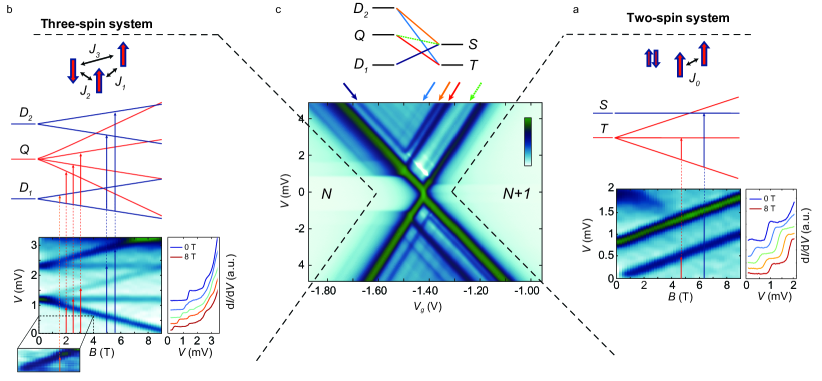
Using the ability to control the energy levels with the gate, the COT analysis can be complemented by a SET spectroscopy in the central part of Fig. 11(c). Here, “real” charging processes dominate. For example, starting from the ground state , addition of a single electron leads to occupation of the ground state. This is evidenced by the clear presence of a SET regime of transport down to the linear-response limit. Inside the resonant regime additional lines parallel to the edges of the cross appear as well. As we explained in Fig. 3, these correspond to “real” charging processes where excess (deficit) energy is used to excite (relax) the molecule. These additional lines, schematized for our experiment in Fig. 12(a), fall into two categories according to the criteria:
-
(a)
Lines terminating at the boundary of the SET regime correspond to the ground to excited transitions or vice versa.
-
(b)
Lines that never reach the SET boundary, but terminate inside the SET regime at a line parallel to this boundary. These correspond to excited to excited transitions. Their earlier termination indicates that that the initial excited state must become first occupied through another process. The line at which it terminates corresponds to the onset of this “activating” process.
In Fig. 11(c) and Fig. 12(a) the SET transitions , and fall into category (a), while the and transitions belong to (b). Due to the large difference in spin-length values of the spin-spectra the latter transition, marked in dashed-green, is actually forbidden by the selection rules (3). Following this line, we find that it terminates at a strong negative differential conductance (NDC) feature (white in the stability diagram in Fig. 11) marking the onset of the transition .
To test our earlier level assignment based COT, we now compute the expected SET transport spectrum the first-order () master equations (7)-(9) and by adjusting the result, we extract quantitative information about the tunnel coupling. The model Hamiltonian is constructed from the energies (26)-(27) and their observed spin-degeneracies. Assuming that spin is conserved in the tunneling, the rates between magnetic sublevels are fixed by Clebsch-Gordan spin-coupling coefficients Romeike et al. (2006, 2007) incorporating both the SET and COT selection rules Eqs. (3) and (17). The tunnel parameters in units of an overall scale are adjusted to fit the relative experimental intensities:
| (28) |
and
| (29) |
Their relative magnitudes provide further input the further microscopic modeling of the 3-4 spin system mentioned at the end of Sec. III.3.1. As shown in Fig. 12(b), the resonant (SET) part of the experimental conductance in Fig. 11(c), as schematized in Fig. 12(a) is reproduced in detail. This includes transitions exciting the molecule from its ground states, but also a transition between excited states.foo (d) The NDC effect is explained in more detail later on together with the full calculation in Fig. 15.
III.3.3 Connecting the off-resonant and resonant analyses
As discussed in Fig. 4-5 and indicated in Fig. 12(a) the SET excitations corresponding to the ground to excited transitions connect continuously to the COT excitations. Those corresponding to two excited states, each of a different charge state, has no corresponding COT excitation to connect to. In this sense, the SET spectrum effectively ties the two separately-obtained COT spin spectra and allows a consistency check on their respective level assignments, cf. Sec. II.3.2.
For instance, from the fact that the transition is clearly visible —marked red in Fig. 11(c)— we conclude that the first excited multiplet of the charge state cannot be a sextuplet () since such SET transition would be spin-forbidden and thus weak. Another example is given by the presence of the SET transition [orange in Fig. 11(c)], which implies that the second excited multiplet of the charge state cannot be a quartet. The fact that this transition does not continue into any of the COT ones is also consistent with its excited-to-excited character.
These two exclusions considerations were anticipated in Sec. III.3.1 and are crucial for our off-resonant assignment in the three-electron state and has now allowed us to reverse-engineer the effective many-electron molecular Hamiltonian. With this in hand, we turn to the main experimental findings and investigate the ”nonequilibrium” COT through the molecule [Sec. III.4] and the crossover regime where “real” and “virtual” tunneling nontrivially compete in the relaxation of spin excitations [Sec. III.5].
III.4 Pump-probe spin spectroscopy by nonequilibrium electron COT
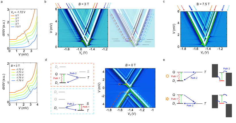
We first investigate how COT spectrum evolves as we further approach the SET regime from either side. Fig. 13(a) shows the analogous of Fig. 11(a) but closer to the SET regime, at V. A horizontal, -field independent line appears (dotted green line in the center-panel schematic) that terminates at T, precisely upon crossing the intra-triplet excitation (blue line). This indicates that the excited triplet (spin perpendicular to the field, ) lives long enough for a secondary COT process to excite the system to the singlet state (reducing the spin length to ). Strong evidence for this is the termination of this line: once the initial state ( excited triplet) for this transition is no longer accessible for , the ”nonequilibrium” cascade of transitions is interrupted.
We consistently observe this effect, also when approaching the SET regime from the side of the other charge state () with different spin. In Fig. 13(b) we show the magnetic field spectrum taken at V. Here the lowest excitation gains strengthfoo (e) relative to Fig. 11(b). In this case, the excited state is the starting point of a ”nonequilibrium” cascade. As for the previous case, it terminates when levels cross at T for similar reasons: Once the state gains occupation for (since the transition becomes energetically more favorable) the excited -substates of the multiplet are depleted causing the line to terminate. In both charge states, the observed COT current gives an estimate for the spin-relaxation time, s.
Nonequilibrium transitions can thus give rise to clear excitations at lower energy than expected from the simple selection-rule plus equilibrium arguments of Sec. III.1. In this type of processes, two COT event () happen in sequence, so that a total of four electrons are involved.foo (f) In this sense, the phenomena can be regarded as a single-molecule electronic pump-probe experiment, that is, the excess energy left behind by the first process (pump) allows the second process to reach states (probe) that would be otherwise inaccessible at the considered bias voltage. This has been successfully applied in STM studies Loth et al. (2010); Heinrich et al. (2013) for dynamical spin-control.
III.5 Mirages of spin transitions “far from resonance”
Mirages.—
We now further reduce the distance to resonance, again coming from either side, and enter the crossover regime discussed in Sec. II.3. We are, however, still “well away from resonance” by the linear-response condition (5).
In the upper panel of Fig. 14(a) we show dd traces taken at various magnetic fields for a constant gate voltage V. At high bias voltage the dd steeply rises due to the onset of the main SET resonance. Below this onset, we note a step-like excitation at meV (black arrow) which shifts up in magnetic field with the same -factor () as the other lower-lying COT excitations.foo (g) If one adopts the off-resonant picture this excitation is attributed to the opening of an independent COT “channel”. This attribution proves to be erroneous: Keeping T fixed and varying the gate voltage (Fig. 14(a), lower panel), we observe that the lower excitations are left unchanged, whereas the higher one under consideration shifts linearly with , revealing that it is not a COT excitation.
This attribution to COT can be further ruled out by looking at the full gate-voltage dependence in the stability diagram shown in the left panel of Fig. 14(b). The excitation (red arrow) has the same gate dependence as the SET resonances, even though it is definitely not in the resonant regime by the linear-response criterion (5). In fact, it is a COSET mirage of the same lowest gate-voltage independent COT excitation as we explained in Fig. 6. Its bias (energy) position does not provide information about the excitation energy : depending on the energy level position the mirage’s excitation voltage can lie anywhere above the COT threshold voltage , see Sec. II.3.
In the stability diagram in the right panel of Fig. 14(b), we connect by dashed lines all the COSET resonances to their corresponding SET excitations according to the scheme in Fig. 6. We find that mirages appear for virtually all spin-related excitations of the molecule. The stability diagram in Fig. 14(c) [same color coding as in (b)] shows that at high magnetic field T these mirages persist.
The clearly visible COSET resonances mark the lines where the relaxation mechanism changes from “virtual” (COT) to “real” (SET) charging. They indicate that any intrinsic relaxation is comparable or slower than SET.999(If the intrinsic relaxation was much faster, compared to SET, it would dominate everywhere, giving a much smaller change in the current at COSET resonances.) Mirages are thus a signature of slow intramolecular relaxation, in particular they indicate that the intrinsic relaxation time is bounded from below by the magnitude of the observed SET currents s, consistent with the sharper lower bound we obtained above from nonequilibrium COT spectroscopy.
Spin relaxation.—
To shed light on what the relaxation mechanism by transport entails in our device, we return to the stability diagram for T, which is shown as dd in the right panel of Fig. 14(d). Highlighted at negative bias are the two crossover-regime bands within which COSET, rather than COT, dominates the relaxation. The left panel shows the different relaxation paths for these two bands.
Focusing on the orange band, we start out on the far left of Fig. 14(d) moving at fixed bias meV along the onset of inelastic COT. Fig. 14(e) depicts the corresponding energies (left) and energy differences (right). Here, the molecule is in the spin-doublet ground state and is occasionally excited to the high-spin quartet by COT from where it relaxes via path 1 ( s), again by COT.
When reaching the circle () in Fig. 14(d) the relaxation mechanism changes: path 1 is overridden by the faster relaxation path 2 ( s) which becomes energetically allowed [Eq. (22)]. The top panel of Fig. 14(e) illustrates that although the ground state is off-resonant (highlighted in red), after exciting it by COT to —increasing the spin-length— the system has enough spin-exchange energy (green) to expel a single electron in a “real” tunneling processes leaving a charged triplet state behind.
At the star () in Fig. 14(d) the excitation mechanism changes from off-resonant to resonant, leaving the relaxation path unaltered. Now the ground state becomes unstable with respect to “real” charging: there is enough energy to expel an electron to the right electrode and sequentially accept another one from the left. We thus have an resonant SET transport cycle, i.e., the stationary state is a statistical mixture of the and ground states.
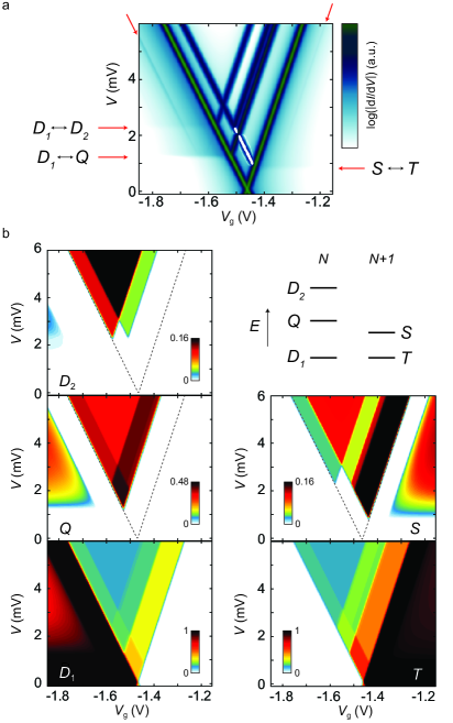
The COSET regime is delimited by mirage resonances and situated between the two positions and . Failure to identify the difference between this ”band” and the pure COT happening on the left of , besides yielding a wrong qualitative spin multiplet structure, leads to an overestimation of the relaxation time: in the COSET regime the spin-excitations created by inelastic COT are quenched.
Quenching of spin-excitations.—
We now assess this quenching in detail for the experimental situation by a calculation based on the master equation Leijnse and Wegewijs (2008); Koller et al. (2010) (23) that includes all and processes using the model determined earlier [Eqs. (26)-(29)], simulating the broadening as before by an effective temperature [Fig. 12].
The computed conductance for is shown in Fig. 15(a). Besides the SET excitations —including the NDC effect— obtained earlier in Fig. 12(c), we capture the main features of the experimental data in Fig. 12(c) and Fig. 14(d): the three horizontal COT excitations and two prominent COSET lines.
We can now explore the nonequilibrium occupations of the five spin-multiplets as the transport spectrum is traversed. These are shown in Fig. 15(b). The lowest panels show in the left (right) off-resonant regime the ground multiplet with electrons ( with electrons) is occupied with probability 1 at low bias voltage (black regions). In contrast, in the resonant regime these two ground states are both partially occupied due to SET processes. We compare the occupations along three different vertical dd line cuts in Fig. 15(a).
(i) Increasing the bias voltage in the resonant regime, starting from V, one first encounters in Fig. 15(a) a dd dip (NDC, white). This is caused by the occupation of the state, as the -panel in Fig. 15(b) shows. This drains so much probability from the multiplet [with a higher transition rate to the multiplet, Eq. (28)-(29)] that the current goes down. Increasing the bias further depopulates the state again, thereby restoring the SET current through a series of dd peaks.
(ii) Increasing the bias voltage starting from the right off-resonant regime the excited -state becomes populated by COT decreasing the average spin-length of the molecule. When crossing the COSET resonance at higher bias this excitation is completely quenched (white diagonal band) well before reaching the resonant regime, enhances the molecular spin, restoring the triplet.
(iii) When starting from the left off-resonant regime, the population of the excited -state enhances the average spin-length of the molecule. As before, crossing the COSET resonance at higher bias quenches this excitation. Now this reduces molecular spin, restoring the doublet. Along the way, the state also becomes occupied by COT and subsequently quenched by COSET. Because of its higher energy, the white COSET band in the -panel of Fig. 15(b) is much broader.
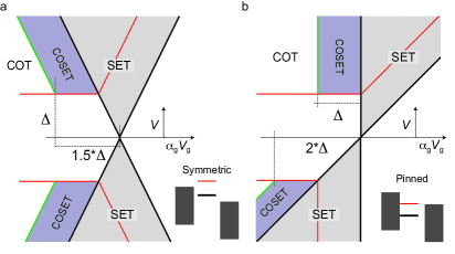
III.6 How far is “off-resonant” ?
The results show that the widths of the two bands where the COT excitations are quenched by COSET are unrelated to the width of the SET resonances, set by the maximum of and . They are, instead, set by the excitation spectrum one wishes to probe.
In Fig. 16(a) we quantify how far the energy level has to be detuned from resonance in order avoid this quenching in our molecular QD device structure. When this detuning lies in the window one is sure to run into the COSET band with increasing bias. Only for there is a finite window where the excitation is not quenched. For the excitations , , in our experiment, this amounts to , , and times the SET resonance width.
In Fig. 16(b) we show the corresponding construction for strong capacitive asymmetry typical of STM setups. To avoid quenching for any bias polarity, one now needs to stay further away from resonance . Interestingly, for COT excitation at forward is not quenched, whereas at reverse bias it is. For asymmetric junctions, the COSET mechanism thus leads to a strong bias-polarity dependence of relaxation of excitations in the nominal off-resonant regime. For one is sure to run into the COSET band for forward bias.
Whereas in the present experiment we encountered relatively low-lying spin-excitations ( few meV) atomic and molecular devices can boast such excitations up to tens of meV. To gauge the impact of COSET mirage resonances, consider an excitation at meV that we wish to populate by COT, e.g., for the purpose of spin-pumping Loth et al. (2010); Heinrich et al. (2013). To avoid the quenching of this excitation the distance to the Fermi-energy at (level-alignment) needs to exceed room temperature, even when operating the device at mK temperatures. For vibrational and electronic excitations on the 100 meV scale the implications are more severe. Moreover, even for excitations that do satisfy these constraints, cascades of ”nonequilibrium” COT excitation may —if even higher excitations are available (e.g., vibrations)— provide a path to excitations that do decay by SET processes. Whereas all these effects can be phrased loosely as “heating” in this paper we demonstrated the discrete nature of these processes, their in-situ tuneability, and the role they play as a spectroscopic tool.
IV Summary and Outlook
We have used electron transport on a single-molecule system to comprehensively characterize the spin degree of freedom and its interaction with the tunneling electrons. Three key points —applicable to a large class of systems— emerged with particular prominence:
(i) Combining SET and COT spectroscopy in a single stable device provides new tools for determining spin properties within and across molecular redox states. This is crucially relevant for the understanding of the different spin-relaxation mechanisms, even in a single redox state.
(ii) Nonequilibrium pump-probe electron excitation using two COT processes (four electrons) was demonstrated in our three-terminal molecular device and signals a substantial intrinsic spin relaxation time of about 1 ns, much larger than the transport times.
(iii) Mirages of resonances arise from the nontrivial interplay of SET and COT. These COSET resonances signal a sharp increase of the relaxation rate and can occur far away from resonance (many times the resonance width). This limits the regime where spin-pumping works by quenching nonequilibrium populations created by a COT current.
The appearance of a mirage of a certain COT excitation indicates that the relaxation of the corresponding molecular degree of freedom dominates over all possible unwanted, intrinsic mechanism. Thus, “good devices show mirages” and “even better devices” show nonequilibrium COT transitions.
Energy level control turns out to be essential for “imaging” in energy space, distinguishing mirages from real excitations. Whereas real-space imaging seems to be of little help in this respect, the mechanical gating possible with scanning probes overcomes this problem. However, even when energy-level control is available, spectroscopy of molecular junctions still requires extreme care as we illustrated in Sec. II.4 by several examples that break spectroscopic rules. Moreover, our work underlines that level alignment has to be treated on a more similar footing as as coupling () and temperature () broadening in the engineering of molecular spin structures and their spin-relaxation rates Loth et al. (2010); Heinrich et al. (2013).
Beyond electron charge transport, recent theoretical work Gergs et al. (2015, ) has pointed out that importance of COSET is amplified when moving to nanoscale transport of heat Galperin, Ratner, and Nitzan (2007). Whereas in charge transport all electrons carry the same charge, in energy transport electrons involved in COSET processes effectively can carry a quite different energy from that acquired in a COT process only and therefore dominate energy currents Gergs et al. (2015, ). Thus, the sensitivity to spin-relaxation processes is dramatically increased in heat transport, indicating an interesting avenue Gergs et al. for a spin-caloritronics Bauer, Saitoh, and van Wees (2012) on the nanoscale.
Acknowledgements.
We thank A. Cornia for the synthesis of the molecules, M. Leijnse and M. Josefsson for assistance with the calculations, and S. Lounis, M. dos Santos Dias and T. Esat for discussions. We acknowledge financial support by the Dutch Organization for Fundamental research (NWO/FOM) and an advanced ERC grant (Mols@Mols). M. M. acknowledges financial support from the Polish Ministry of Science and Higher Education through a young scientist fellowship (0066/E-336/9/2014), and from the Polish Ministry of Science and Education as Iuventus Plus project (IP2014 030973) in years 2015-2017. E.B. thanks funds from the EU FP7 program, Project 618082 ACMOL through a NWO-VENI fellowship.References
- Bartolomé, Luis, and Fernández (2014) J. Bartolomé, F. Luis, and J. F. Fernández, eds., Molecular magnets: Physics and applications, NanoScience and Technology (Springer, Heidelberg, 2014).
- Huang et al. (2015) C. Huang, A. V. Rudnev, W. Hong, and T. Wandlowski, “Break junction under electrochemical gating: testbed for single-molecule electronics,” Chem. Soc. Rev. 44, 889–901 (2015).
- Moth-Poulsen (2016) K. Moth-Poulsen, ed., Handbook of single-molecule electronics (Pan Stanford Publishing Pte. Ltd, Singapore, 2016).
- Perrin, Burzurí, and van der Zant (2015) M. L. Perrin, E. Burzurí, and H. S. J. van der Zant, “Single-molecule transistors,” Chem. Soc. Rev. 44, 902–919 (2015).
- Chen, Hong, and Huang (2012) Y.-S. Chen, M.-Y. Hong, and G. S. Huang, “A protein transistor made of an antibody molecule and two gold nanoparticles,” Nature nanotechnology 7, 197–203 (2012).
- Seeman (2003) N. C. Seeman, “Dna in a material world,” Nature 421, 427–431 (2003).
- Xie et al. (2011) Z. Xie, T. Z. Markus, S. R. Cohen, Z. Vager, R. Gutierrez, and R. Naaman, “Spin specific electron conduction through dna oligomers,” Nano Lett 11, 4652–5 (2011).
- Naaman and Waldeck (2015) R. Naaman and D. H. Waldeck, “Spintronics and chirality: spin selectivity in electron transport through chiral molecules,” Annu Rev Phys Chem 66, 263–81 (2015).
- Burzurí et al. (2014) E. Burzurí, Y. Yamamoto, M. Warnock, X. Zhong, K. Park, A. Cornia, and H. S. J. van der Zant, “Franck–Condon blockade in a single-molecule transistor,” Nano Lett. 14, 3191–3196 (2014).
- Franke and Pascual (2012) K. J. Franke and J. I. Pascual, “Effects of electron–vibration coupling in transport through single molecules,” J. Phys.: Condens. Matter 24, 394002 (2012).
- Franke, Schulze, and Pascual (2011) K. J. Franke, G. Schulze, and J. I. Pascual, “Competition of superconducting phenomena and kondo screening at the nanoscale,” Science 332, 940–944 (2011).
- Island et al. (2016) J. O. Island, R. Gaudenzi, J. de Bruijckere, E. Burzurí, C. Franco, M. Mas-Torrent, C. Rovira, J. Veciana, T. M. Klapwijk, R. Aguado, et al., “Proximity-induced shiba states in a molecular junction,” arXiv preprint arXiv:1609.08316 (2016).
- Frisenda et al. (2015) R. Frisenda, R. Gaudenzi, C. Franco, M. Mas-Torrent, C. Rovira, J. Veciana, I. Alcon, S. T. Bromley, and H. S. J. Burzurí, E. andvan der Zant, “Kondo effect in a neutral and stable all organic radical single molecule break junction,” Nano Lett. 15, 3109–3114 (2015).
- Koole et al. (2015) M. Koole, J. M. Thijssen, H. Valkenier, J. C. Hummelen, and H. S. van der Zant, “Electric-field control of interfering transport pathways in a single-molecule anthraquinone transistor,” Nano Lett 15, 5569–73 (2015).
- Thiele et al. (2014) S. Thiele, F. Balestro, R. Ballou, S. Klyatskaya, M. Ruben, and W. Wernsdorfer, “Electrically driven nuclear spin resonance in single-molecule magnets,” Science 344, 1135–1138 (2014).
- Meservey and Tedrow (1994) R. Meservey and P. Tedrow, “Spin-polarized electron tunneling,” Phys. Rep. 238, 173–243 (1994).
- Nussinov, Crommie, and Balatsky (2003) Z. Nussinov, M. Crommie, and A. Balatsky, “Noise spectroscopy of a single spin with spin-polarized STM,” Phys. Rev. B 68, 085402 (2003).
- Heinrich et al. (2004) A. J. Heinrich, J. A. Gupta, C. P. Lutz, and D. M. Eigler, “Single-atom spin-flip spectroscopy,” Science 306, 466–469 (2004).
- Meier et al. (2008) F. Meier, L. Zhou, J. Wiebe, and R. Wiesendanger, “Revealing magnetic interactions from single-atom magnetization curves,” Science 320, 82–86 (2008).
- Chen et al. (2008) X. Chen, Y.-S. Fu, S.-H. Ji, T. Zhang, P. Cheng, X.-C. Ma, X.-L. Zou, W.-H. Duan, J.-F. Jia, and Q.-K. Xue, “Probing superexchange interaction in molecular magnets by spin-flip spectroscopy and microscopy,” Phys. Rev. Lett. 101, 197208 (2008).
- Wiesendanger (2009) R. Wiesendanger, “Spin mapping at the nanoscale and atomic scale,” Rev. Mod. Phys. 81, 1495 (2009).
- Petukhov et al. (2009) K. Petukhov, M. S. Alam, H. Rupp, S. Strömsdörfer, P. Müller, A. Scheurer, R. W. Saalfrank, J. Kortus, A. Postnikov, M. Ruben, L. K. Thompson, and J.-M. Lehn, “Stm spectroscopy of magnetic molecules,” Coord. Chem. Rev. 253, 2387–2398 (2009).
- Kahle and et al. (2012) S. Kahle and et al., “The quantum magnetism of individual manganese-12-acetate molecular magnets anchored at surfaces,” Nano Lett. 12, 518–521 (2012).
- Gauyacq, Lorente, and Novaes (2012) J.-P. Gauyacq, N. Lorente, and F. D. Novaes, “Excitation of local magnetic moments by tunneling electrons,” Prog. Surf. Sci. 87, 63–107 (2012).
- Ternes (2015) M. Ternes, “Spin excitations and correlations in scanning tunneling spectroscopy,” New J. Phys. 17, 063016 (2015).
- Burgess et al. (2015) J. A. J. Burgess, L. Malavolti, V. Lanzilotto, M. Mannini, S. Yan, S. Ninova, F. Totti, S. Rolf-Pissarczyk, A. Cornia, R. Sessoli, and S. Loth, “Magnetic fingerprint of individual Fe4 molecular magnets under compression by a scanning tunnelling microscope,” Nature Comm. 6, 8216 (2015).
- Heinrich et al. (2015) B. W. Heinrich, L. Braun, J. I. Pascual, and K. J. Franke, “Tuning the magnetic anisotropy of single molecules,” Nano Lett. 15, 4024–4028 (2015).
- Böhler et al. (2004) T. Böhler, J. Grebing, A. Mayer-Gindner, H. v Löhneysen, and E. Scheer, “Mechanically controllable break-junctions for use as electrodes for molecular electronics,” Nanotechnology 15, S465–S471 (2004).
- Champagne, Pasupathy, and Ralph (2005) A. R. Champagne, A. N. Pasupathy, and D. C. Ralph, “Mechanically-adjustable and electrically-gated single-molecule transistors,” Nano Lett. 5, 305 (2005).
- Chae et al. (2006) D.-H. Chae, J. F. Berry, S. Jung, F. A. Cotton, C. A. Murillo, and Z. Yao, “Vibrational excitations in single trimetal-molecule transistors,” Nano Lett. 6, 165–168 (2006).
- Galperin, Ratner, and Nitzan (2007) M. Galperin, M. A. Ratner, and A. Nitzan, “Molecular transport junctions: vibrational effects,” J. Phys.: Condens. Matter 19, 103201 (2007).
- Hihath et al. (2008) J. Hihath, C. R. Arroyo, G. Rubio-Bollinger, N. Tao, and N. Agraït, “Study of electron-phonon interactions in a single molecule covalently connected to two electrodes,” Nano Lett. 8, 1673–1678 (2008).
- Hüttel et al. (2009) A. K. Hüttel, B. Witkamp, M. Leijnse, M. R. Wegewijs, and H. S. J. van der Zant, “Pumping of vibrational excitations in the Coulomb-blockade regime in a suspended carbon nanotube,” Phys. Rev. Lett. 102, 225501 (2009).
- Parks et al. (2007) J. Parks, A. Champagne, G. Hutchison, S. Flores-Torres, H. Abruna, and D. Ralph, “Tuning the Kondo effect with a mechanically controllable break junction,” Phys. Rev. Lett. 99, 026601 (2007).
- Parks et al. (2010) J. J. Parks, A. R. Champagne, T. A. Costi, W. W. Shum, A. N. Pasupathy, E. Neuscamman, S. Flores-Torres, P. S. Cornaglia, A. A. Aligia, C. A. Balseiro, G. K.-L. Chan, H. D. Abuña, and D. C. Ralph, “Mechanical control of spin states in spin-1 molecules and the underscreened Kondo effect,” Science 328, 1370–1373 (2010).
- Hanson et al. (2007) R. Hanson, L. P. Kouwenhoven, J. R. Petta, S. Tarucha, and L. M. K. Vandersypen, “Spins in few-electron quantum dots,” Rev. Mod. Phys 79, 1217 (2007).
- Jarillo-Herrero et al. (2004) P. Jarillo-Herrero, S. Sapmaz, C. Dekker, L. Kouwenhoven, and H. van der Zant, “Electron-hole symmetry in a semiconducting carbon nanotube quantum dot,” Nature 429, 389–392 (2004).
- Koppens et al. (2005) F. H. L. Koppens, J. A. Folk, J. M. Elzerman, R. Hanson, L. H. W. van Beveren, I. T. Vink, H.-P. Tranitz, W. Wegscheider, L. P. Kouwenhoven, and L. M. K. Vandersypen, “Control and detection of singlet-triplet mixing in a random nuclear field,” Science 309, 1346–1350 (2005).
- Jarillo-Herrero et al. (2005) P. Jarillo-Herrero, J. Kong, H. S. J. van der Zant, C. Dekker, L. P. Kouwenhoven, and S. De Franceschi, “Electronic transport spectroscopy of carbon nanotubes in a magnetic field,” Phys. Rev. Lett. 94, 156802 (2005).
- Sapmaz et al. (2005) S. Sapmaz, P. Jarillo-Herrero, J. Kong, C. Dekker, L. P. Kouwenhoven, and H. S. J. van der Zant, “Electronic excitation spectrum of metallic carbon nanotubes,” Phys. Rev. B 71, 153402 (2005).
- Hüttel et al. (2005) A. K. Hüttel, S. Ludwig, H. Lorenz, K. Eberl, and J. P. Kotthaus, “Direct control of the tunnel splitting in a one-electron double quantum dot,” Phys. Rev. B 72, 081310 (2005).
- Gräber et al. (2006) M. R. Gräber, W. A. Coish, C. Hoffmann, M. Weiss, J. Furer, S. Oberholzer, D. Loss, and C. Schönenberger, “Molecular states in carbon nanotube double quantum dots,” Phys. Rev. B 74, 075427 (2006).
- Sapmaz et al. (2006) S. Sapmaz, P. Jarillo-Herrero, L. P. Kouwenhoven, and H. S. J. van der Zant, “Quantum dots in carbon nanotubes,” Semicond. Sci. Technol. 21, S52–S63 (2006).
- Leturcq et al. (2009) R. Leturcq, C. Stampfer, K. Inderbitzin, L. Durrer, C. Hierold, E. Mariani, M. G. Schultz, F. von Oppen, and K. Ensslin, “Franck–condon blockade in suspended carbon nanotube quantum dots,” Nature Phys. 5, 327–331 (2009).
- Andergassen et al. (2010) S. Andergassen, V. Meden, H. Schoeller, J. Splettstoesser, and M. R. Wegewijs, “Charge transport through single molecules, quantum dots and quantum wires,” Nanotechnology 21, 272001 (2010).
- Haupt et al. (2013) F. Haupt, M. Leijnse, H. L. Calvo, L. Classen, J. Splettstoesser, and M. R. Wegewijs, “Heat, molecular vibrations, and adiabatic driving in non-equilibrium transport through interacting quantum dots,” Phys. Status Solidi B 250, 2315–2329 (2013).
- Heersche et al. (2006a) H. B. Heersche, Z. de Groot, J. A. Folk, H. S. J. van der Zant, C. Romeike, M. R. Wegewijs, L. Zobbi, D. Barreca, E. Tondello, and A. Cornia, “Electron transport through single molecular magnets,” Phys. Rev. Lett. 96, 206801 (2006a).
- Zyazin et al. (2010) A. Zyazin, J. van den Berg, E. Osorio, H. van der Zant, N. Konstantinidis, M. Leijnse, M. Wegewijs, F. May, W. Hofstetter, C. Danieli, and A. Cornia, “Electric field controlled magnetic anisotropy in a single molecule,” Nano Lett. 10, 3307–3311 (2010).
- Burzurí et al. (2012) E. Burzurí, A. S. Zyazin, A. Cornia, and H. S. J. van der Zant, “Direct observation of magnetic anisotropy in an individual single-molecule magnet,” Phys. Rev. Lett. 109, 147203 (2012).
- Misiorny et al. (2015) M. Misiorny, E. Burzurí, R. Gaudenzi, K. Park, M. Leijnse, M. R. Wegewijs, J. Paaske, A. Cornia, and H. S. J. van der Zant, “Probing transverse magnetic anisotropy by electronic transport through a single-molecule magnet,” Phys. Rev. B 91, 035442 (2015).
- Burzurí, Gaudenzi, and van der Zant (2015) E. Burzurí, R. Gaudenzi, and H. S. J. van der Zant, “Observing magnetic anisotropy in electronic transport through individual single-molecule magnets,” J. Phys.: Condens. Matter 27, 113202 (2015).
- Grose et al. (2008) J. E. Grose, E. S. Tam, C. Timm, M. Scheloske, B. Ulgut, J. J. Parks, H. D. Abruña, W. Harneit, and D. C. Ralph, “Tunneling spectra of individual magnetic endofullerene molecules,” Nature Mater. 7, 884 (2008).
- Kogan et al. (2003) A. Kogan, G. Granger, M. Kastner, D. Goldhaber-Gordon, and H. Shtrikman, “Singlet–triplet transition in a single-electron transistor at zero magnetic field,” Phys. Rev. B 67, 113309 (2003).
- Craig et al. (2004) N. Craig, J. Taylor, E. Lester, C. Marcus, M. Hanson, and A. Gossard, “Tunable nonlocal spin control in a coupled-quantum dot system,” Science 304, 565–567 (2004).
- Moriyama et al. (2005) S. Moriyama, T. Fuse, M. Suzuki, Y. Aoyagi, and K. Ishibashi, “Four-electron shell structures and an interacting two-electron system in carbon-nanotube quantum dots,” Phys. Rev. Lett. 94, 186806 (2005).
- Florens et al. (2011) S. Florens, A. Freyn, N. Roch, W. Wernsdorfer, F. Balestro, P. Roura-Bas, and A. Aligia, “Universal transport signatures in two-electron molecular quantum dots: gate-tunable Hund’s rule, underscreened Kondo effect and quantum phase transitions,” J. Phys.: Condens. Matter 23, 243202 (2011).
- Grove-Rasmussen et al. (2012) K. Grove-Rasmussen, S. Grap, J. Paaske, K. Flensberg, S. Andergassen, V. Meden, H. I. Jørgensen, K. Muraki, and T. Fujisawa, “Magnetic-field dependence of tunnel couplings in carbon nanotube quantum dots,” Phys. Rev. Lett. 108, 176802 (2012).
- Mason, Biercuk, and Marcus (2004) N. Mason, M. J. Biercuk, and C. M. Marcus, “Local gate control of a carbon nanotube double quantum dot,” Science 303, 655–658 (2004).
- Biercuk et al. (2005) M. J. . Biercuk, S. Garaj, N. Mason, J. M. Chow, and C. M. Marcus, “Gate-defined quantum dots on carbon nanotubes,” Nano Lett. 5, 1267–1271 (2005).
- Hauptmann, Paaske, and Lindelof (2008) J. Hauptmann, J. Paaske, and P. Lindelof, “Electric-field-controlled spin reversal in a quantum dot with ferromagnetic contacts,” Nature Phys. 4, 373–376 (2008).
- Song et al. (2009) H. Song, Y. Kim, Y. H. Jang, H. Jeong, M. A. Reed, and T. Lee, “Observation of molecular orbital gating,” Nature 462, 1039–1043 (2009).
- Jespersen et al. (2011a) T. S. Jespersen, K. Grove-Rasmussen, J. Paaske, K. Muraki, T. Fujisawa, J. Nygård, and K. Flensberg, “Gate-dependent spin-orbit coupling in multielectron carbon nanotubes,” Nature Phys. 7, 348–353 (2011a).
- Schleser et al. (2005) R. Schleser, T. Ihn, E. Ruh, K. Ensslin, M. Tews, D. Pfannkuche, D. C. Driscoll, and A. C. Gossard, “Cotunneling-mediated transport through excited states in the coulomb-blockade regime,” Phys. Rev. Lett. 94, 206805 (2005).
- Hüttel et al. (2008) A. K. Hüttel, M. Poot, B. Witkamp, and H. S. J. van der Zant, “Nanoelectromechanics of suspended carbon nanotubes,” New J. Phys. 10, 095003 (2008).
- Golovach and Loss (2004) V. N. Golovach and D. Loss, “Transport through a double quantum dot in the sequential tunneling and cotunneling regimes,” Phys. Rev. B 69, 245327 (2004).
- Aghassi, Hettler, and Schön (2008) J. Aghassi, M. H. Hettler, and G. Schön, “Cotunneling assisted sequential tunneling in multilevel quantum dots,” Appl. Phys. Lett. 92, 202101 (2008).
- Lüffe, Koch, and von Oppen (2008) M. C. Lüffe, J. Koch, and F. von Oppen, “Theory of vibrational absorption sidebands in the coulomb-blockade regime of single-molecule transistors,” Phys. Rev. B 77, 125306 (2008).
- Becker and Pfannkuche (2008) D. Becker and D. Pfannkuche, “Coulomb-blocked transport through a quantum dot with spin-split level: Increase of differential conductance peaks by spin relaxation,” Phys. Rev. B 77, 205307 (2008).
- Weymann (2008) I. Weymann, “Effects of different geometries on the conductance, shot noise, and tunnel magnetoresistance of double quantum dots,” Phys. Rev. B 78, 045310 (2008).
- Leijnse and Wegewijs (2008) M. Leijnse and M. R. Wegewijs, “Kinetic equations for transport through single-molecule transistors,” Phys. Rev. B 78, 235424 (2008).
- Thijssen and van der Zant (2008) J. M. Thijssen and H. S. J. van der Zant, “Charge transport and single-electron effects in nanoscale systems,” Phys. Status Soidi B 245, 1455–1470 (2008).
- Ferry, Goodnick, and Bird (2009) D. Ferry, S. M. Goodnick, and J. Bird, Transport in nanostructures, 2nd ed. (Cambridge University Press, Cambridge, 2009).
- Cuevas and Scheer (2010) J. C. Cuevas and E. Scheer, Molecular electronics: An introduction to theory and experiment, World Scientific Series in Nanoscience and Nanotechnology, Vol. 1 (World Scientific, Singapore, 2010).
- Tarucha et al. (2000) S. Tarucha, D. Austing, Y. Tokura, W. van der Wiel, and L. Kouwenhoven, “Direct coulomb and exchange interaction in artificial atoms,” Phys. Rev. Lett. 84, 2485–2488 (2000).
- Oosterkamp et al. (1998) T. H. Oosterkamp, T. Fujisawa, W. G. Van Der Wiel, K. Ishibashi, R. V. Hijman, S. Tarucha, and L. P. Kouwenhoven, “Microwave spectroscopy of a quantum-dot molecule,” Nature 395, 873–876 (1998).
- Maksym et al. (2000) P. A. Maksym, H. Imamura, G. P. Mallon, and H. Aoki, “Molecular aspects of electron correlation in quantum dots,” J. Phys.: Condens. Matter 12, R299–R334 (2000).
- Fujisawa et al. (2002) T. Fujisawa, D. G. Austing, Y. Tokura, Y. Hirayama, and S. Tarucha, “Allowed and forbidden transitions in artificial hydrogen and helium atoms,” Nature 419, 278–281 (2002).
- Begemann et al. (2008) G. Begemann, D. Darau, A. Donarini, and M. Grifoni, “Symmetry fingerprints of a benzene single-electron transistor: Interplay between coulomb interaction and orbital symmetry,” Phys. Rev. B 77, 201406 (2008).
- van der Wiel et al. (2003) W. G. van der Wiel, S. De Franceschi, J. M. Elzerman, T. Fujisawa, S. Tarucha, and L. P. Kouwenhoven, “Electron transport through double quantum dots,” Rev. Mod. Phys. 75, 1 (2003).
- Misiorny, Weymann, and Barnaś (2009) M. Misiorny, I. Weymann, and J. Barnaś, “Spin effects in transport through single-molecule magnets in the sequentail and cotunneling regimes,” Phys. Rev. B 79, 224420 (2009).
- McCaskey et al. (2015) A. McCaskey, Y. Yamamoto, M. Warnock, E. Burzurí, H. S. J. van der Zant, and K. Park, “Electron-vibron coupling effects on electron transport via a single-molecule magnet,” Phys. Rev. B 91, 125419 (2015).
- Vincent et al. (2012) R. Vincent, S. Klyatskaya, W. Ruben, M.and Wernsdorfer, and BalestroF., “Electronic read-out of a single nuclear spin using a molecular spin transistor,” Nature 488, 357–360 (2012).
- Ganzhorn et al. (2013) M. Ganzhorn, S. Klyatskaya, M. Ruben, and W. Wernsdorfer, “Strong spin-phonon coupling between a single-molecule magnet and a carbon nanotube nanoelectromechanical system,” Nature Nanotechn. 8, 165–169 (2013).
- Thiele et al. (2013) S. Thiele, R. Vincent, M. Holzmann, S. Klyatskaya, M. Ruben, F. Balestro, and W. Wernsdorfer, “Electrical readout of individual nuclear spin trajectories in a single-molecule magnet spin transistor,” Phys. Rev. Lett. 111, 037203 (2013).
- Cobden et al. (1998) D. Cobden, M. Bockrath, P. McEuen, A. Rinzler, and R. Smalley, “Spin splitting and even-odd effects in carbon nanotubes,” Phys. Rev. Lett. 81, 681–684 (1998).
- Jespersen et al. (2011b) T. S. Jespersen, K. Grove-Rasmussen, K. Flensberg, J. Paaske, K. Muraki, T. Fujisawa, and J. Nygård, “Gate-dependent orbital magnetic moments in carbon nanotubes,” Phys. Rev. Lett. 107, 186802 (2011b).
- Weber et al. (2015) P. Weber, H. L. Calvo, J. Bohle, K. Goß, C. Meyer, M. R. Wegewijs, and C. Stampfer, “Switchable coupling of vibrations to two-electron carbon-nanotube quantum dot states,” Nano Lett. 15, 4417–4422 (2015).
- Piva et al. (2005) P. G. Piva, G. A. DiLabio, J. L. Pitters, J. Zikovsky, M. Rezeq, S. Dogel, W. A. Hofer, and R. A. Wolkow, “Field regulation of single-molecule conductivity by a charged surface atom,” Nature 435, 658–661 (2005).
- (89) C. A. Martin, J. van Ruitenbeek, and H. S. J. van der Zant, Nanotechnology 21, 26.
- Temirov et al. (2008) R. Temirov, A. Lassise, F. B. Anders, and F. S. Tautz, “Kondo effect by controlled cleavage of a single-molecule contact,” Nanotechnology 19, 065401 (2008).
- Toher et al. (2011a) C. Toher, R. Temirov, A. Greuling, F. Pump, M. Kaczmarski, G. Cuniberti, M. Rohlfing, and F. S. Tautz, “Electrical transport through a mechanically gated molecular wire,” Physical Review B 83, 155402 (2011a).
- Toher et al. (2011b) C. Toher, R. Temirov, A. Greuling, F. Pump, M. Kaczmarski, G. Cuniberti, M. Rohlfing, and F. S. Tautz, “Electrical transport through a mechanically gated molecular wire,” Physical Review B 83, 155402 (2011b).
- Greuling et al. (2011a) A. Greuling, M. Rohlfing, R. Temirov, F. S. Tautz, and F. B. Anders, “Ab initio study of a mechanically gated molecule: From weak to strong correlation,” Physical Review B 84, 125413 (2011a).
- Greuling et al. (2013) A. Greuling, R. Temirov, B. Lechtenberg, F. B. Anders, M. Rohlfing, and F. S. Tautz, “Spectral properties of a molecular wire in the Kondo regime,” Physica Status Solidi (b) 250, 2386–2393 (2013).
- Wagner and Temirov (2015) C. Wagner and R. Temirov, “Tunnelling junctions with additional degrees of freedom: An extended toolbox of scanning probe microscopy,” Progress in Surface Science 90, 194 – 222 (2015).
- Yoo et al. (1997) M. J. Yoo, T. A. Fulton, H. F. Hess, R. L. Willett, L. N. Dunkleberger, R. J. Chichester, L. N. Pfeiffer, and K. W. West, “Scanning single-electron transistor microscopy: Imaging individual charges,” Science 276, 579–582 (1997).
- Wagner et al. (2015) C. Wagner, M. F. B. Green, P. Leinen, T. Deilmann, P. Krüger, M. Rohlfing, R. Temirov, and F. S. Tautz, “Scanning quantum dot microscopy,” Phys. Rev. Lett. 115, 026101 (2015).
- Bruus and Flensberg (2004) H. Bruus and K. Flensberg, Many-body quantum theory in condesed matter physics, Oxford Graduate Texts (Oxford University Press, Oxford, 2004).
- Koch and von Oppen (2005) J. Koch and F. von Oppen, “Franck-Condon blockade and giant Fano factors in transport through single molecules,” Phys. Rev. Lett. 94, 206804 (2005).
- Koch, von Oppen, and Andreev (2006) J. Koch, F. von Oppen, and A. V. Andreev, “Theory of the Franck-Condon blockade regime,” Phys. Rev. B 74, 205438 (2006).
- Reckermann et al. (2008) F. Reckermann, M. Leijnse, M. R. Wegewijs, and H. Schoeller, “Transport signature of pseudo jahn-teller dynamics in a single-molecule transistor,” Europhys. Lett. 83, 58001 (2008).
- Reckermann, Leijnse, and Wegewijs (2009) F. Reckermann, M. Leijnse, and M. R. Wegewijs, “Vibrational detection and control of spin in mixed-valence molecular transistors,” Phys. Rev. B 79, 075313 (2009).
- Beenakker (1991) C. W. J. Beenakker, “Theory of Coulomb-blockade oscillations in the conductance of a quantum dot,” Phys. Rev. B 44, 1646 (1991).
- Kaasbjerg and Flensberg (2011) K. Kaasbjerg and K. Flensberg, “Image charge effects in single-molecule junctions: Breaking of symmetries and negative-differential resistance in a benzene single-electron transistor,” Phys. Rev. B 84, 115457 (2011).
- Lambe and Jaklevic (1968) J. Lambe and R. C. Jaklevic, “Molecular vibration spectra by inelastic electron tunneling,” Phys. Rev. 165, 821–832 (1968).
- Khajetoorians et al. (2012) A. A. Khajetoorians, J. Wiebe, B. Chilian, S. Lounis, S. Blügel, and R. Wiesendanger, “Atom-by-atom engineering and magnetometry of tailored nanomagnets,” Nature Phys. 8, 497–503 (2012).
- Brede and Wiesendanger (2012) J. Brede and R. Wiesendanger, “Spin-resolved characterization of single cobalt phthalocyanine molecules on a ferromagnetic support,” Phys. Rev. B 86, 184423 (2012).
- Khajetoorians et al. (2013) A. A. Khajetoorians, B. Baxevanis, C. Hübner, T. Schlenk, S. Krause, T. O. Wehling, S. Lounis, A. Lichtenstein, D. Pfannkuche, J. Wiebe, and R. Wiesendanger, “Current-driven spin dynamics of artificially constructed quantum magnets,” Science 339, 55–59 (2013).
- Bryant et al. (2013) B. Bryant, A. Spinelli, J. J. T. Wagenaar, M. Gerrits, and A. F. Otte, “Local control of single atom magnetocrystalline anisotropy,” Phys. Rev. Lett. 111, 127203 (2013).
- Rau et al. (2014) I. G. Rau, S. Baumann, S. Rusponi, F. Donati, S. Stepanow, L. Gragnaniello, J. Dreiser, C. Piamonteze, F. Nolting, S. Gangopadhyay, O. R. Albertini, R. M. Macfarlane, C. P. Lutz, B. A. Jones, P. Gambardella, A. J. Heinrich, and H. Brune, “Reaching the magnetic anisotropy limit of a 3d metal atom,” Science 344, 988–992 (2014).
- Hapala et al. (2014) P. Hapala, G. Kichin, C. Wagner, F. S. Tautz, R. Temirov, and P. Jelínek, “Mechanism of high-resolution stm/afm imaging with functionalized tips,” Phys. Rev. B 90, 085421 (2014).
- Wagner et al. (2014) C. Wagner, N. Fournier, V. G. Ruiz, C. Li, K. Müllen, M. Rohlfing, A. Tkatchenko, R. Temirov, and F. S. Tautz, “Non-additivity of molecule-surface van der waals potentials from force measurements,” Nature Commun. 5, 5568 (2014).
- Bazarnik et al. (2016) M. Bazarnik, B. Bugenhagen, M. Elsebach, E. Sierda, A. Frank, M. H. Prosenc, and R. Wiesendanger, “Toward tailored all-spin molecular devices,” Nano Lett. 16, 577–582 (2016).
- Hirjibehedin, Lutz, and Heinrich (2006) C. Hirjibehedin, C. Lutz, and A. Heinrich, “Spin coupling in engineered atomic structures,” Science 312, 1021–1024 (2006).
- Hirjibehedin et al. (2007) C. Hirjibehedin, C. Lin, A. Otte, M. Ternes, C. Lutz, B. Jones, and A. Heinrich, “Large magnetic anisotropy of a single atomic spin embedded in a surface molecular network,” Science 317, 1199–1203 (2007).
- Serrate et al. (2010) D. Serrate, P. Ferriani, Y. Yoshida, S.-W. Hla, M. Menzel, K. von Bergmann, S. Heinze, A. Kubetzka, and R. Wiesendanger, “Imaging and manipulating the spin direction of individual atoms,” Nature Nanotech. 5, 350 (2010).
- Baumann et al. (2015) S. Baumann, F. Donati, S. Stepanow, S. Rusponi, W. Paul, S. Gangopadhyay, I. G. Rau, G. E. Pacchioni, L. Gragnaniello, M. Pivetta, J. Dreiser, C. Piamonteze, C. P. Lutz, R. M. Macfarlane, B. A. Jones, P. Gambardella, A. J. Heinrich, and H. Brune, “Origin of perpendicular magnetic anisotropy and large orbital moment in Fe atoms on MgO,” Phys. Rev. Lett. 115, 237202 (2015).
- Greuling et al. (2011b) A. Greuling, M. Rohlfing, R. Temirov, F. S. Tautz, and F. B. Anders, “Ab initio study of a mechanically gated molecule: From weak to strong correlation,” Phys. Rev. B 84, 125413 (2011b).
- Weiss et al. (2010) C. Weiss, C. Wagner, C. Kleimann, M. Rohlfing, F. S. Tautz, and R. Temirov, “Imaging pauli repulsion in scanning tunneling microscopy,” Phys. Rev. Lett. 105, 086103 (2010).
- Esat et al. (2015) T. Esat, T. Deilmann, B. Lechtenberg, C. Wagner, P. Krüger, R. Temirov, F. B. Anders, M. Rohlfing, and F. S. Tautz, “Transfering spin into an extended orbital of a large molecule,” Phys. Rev. B 91, 144415 (2015).
- Atodiresei et al. (2009) N. Atodiresei, V. Caciuc, P. Lazić, and S. Blügel, “Chemical versus van der waals interaction: The role of the heteroatom in the flat absorption of aromatic molecules C6H6, C5NH5, and C4N2H4 on the Cu(110) surface,” Phys. Rev. Lett. 102, 136809 (2009).
- Loth et al. (2010) S. Loth, K. von Bergmann, M. Ternes, A. Otte, C. Lutz, and A. Heinrich, “Controlling the state of quantum spins with electric currents,” Nature Phys. 6, 340–344 (2010).
- Khajetoorians et al. (2011) A. A. Khajetoorians, S. Lounis, B. Chilian, A. T. Costa, L. Zhou, D. L. Mills, J. Wiebe, and R. Wiesendanger, “Itinerant nature of atom-magnetization excitation by tunneling electrons,” Phys. Rev. Lett. 106, 037205 (2011).
- Yan et al. (2015a) S. Yan, D.-J. Choi, J. A. J. Burgess, S. Rolf-Pissarczyk, and S. Loth, “Three-dimensional mapping of single-atom magnetic anisotropy,” Nano Lett. 15, 1938–1942 (2015a).
- Yan et al. (2015b) S. Yan, D.-J. Choi, J. A. J. Burgess, S. Rolf-Pissarczyk, and S. Loth, “Control of quantum magnets by atomic exchange bias,” Nature Nanotechnol. 10, 40–45 (2015b).
- Khajetoorians et al. (2016) A. A. Khajetoorians, M. Steinbrecher, M. Ternes, M. Bouhassoune, M. dos Santos Dias, S. Lounis, J. Wiebe, and R. Wiesendanger, “Tailoring the chiral magnetic interaction between two individual atoms,” Nature Commun. 7, 10620 (2016).
- Steinbrecher et al. (2016) M. Steinbrecher, A. Sonntag, M. dos Santos Dias, M. Bouhassoune, S. Lounis, J. Wiebe, R. Wiesendanger, and A. A. Khajetoorians, “Absence of a spin-signature from a single ho adatom as probed by spin-sensitive tunneling,” Nature Commun. 7, 10454 (2016).
- Otte et al. (2008) A. Otte, M. Ternes, K. von Bergmann, S. Loth, H. Brune, C. Lutz, C. Hirjibehedin, and A. Heinrich, “The role of magnetic anisotropy in the Kondo effect,” Nature Phys. 4, 847–850 (2008).
- Loth, Lutz, and Heinrich (2010) S. Loth, C. Lutz, and A. Heinrich, “Spin-polarized spin excitation spectroscopy,” New J. Phys. 12, 125021 (2010).
- STM (2014) “Recent advances in scanning tunneling microscopy and spectroscopy,” C. F. Hirjibehedin and Y. Wang, eds., special section in J. Physc.: Condens. Matter 26, 394001–394010 (2014).
- Repp et al. (2005) J. Repp, G. Meyer, S. M. Stojković, A. Gourdon, and C. Joachim, “Molecules on insulating films: Scanning-tunneling microscopy imaging of individual molecular orbitals,” Phys. Rev. Lett 94, 026803 (2005).
- De Franceschi et al. (2001) S. De Franceschi, S. Sasaki, J. Elzerman, W. van der Wiel, S. Tarucha, and L. Kouwenhoven, “Electron cotunneling in a semiconductor quantum dot,” Phys. Rev. Lett. 86, 878–881 (2001).
- Zumbühl et al. (2004) D. M. Zumbühl, C. M. Marcus, M. P. Hanson, and A. C. Gossard, “Cotunneling spectroscopy in few-electron quantum dots,” Phys. Rev. Lett. 93, 256801 (2004).
- Katsaros et al. (2010) G. Katsaros, P. Spathis, M. Stoffel, F. Fournel, M. Mongillo, V. Bouchiat, F. Lefloch, A. Rastelli, O. G. Schmidt, and S. De Franceschi, Nature Nanotech. 5, 458 (2010).
- Jespersen et al. (2011c) T. Jespersen, K. Grove-Rasmussen, J. Paaske, K. Muraki, T. Fujisawa, J. Nygård, and K.Flensberg, “Gate-dependent spin–orbit coupling in multielectron carbon nanotubes,” Nature Phys. 7, 348 (2011c).
- (136) M. R. Wegewijs and Y. V. Nazarov, “Inelastic co-tunneling through an excited state of a quantum dot,” Cond-mat/0103579.
- Hartmann and Wilhelm (2003) U. Hartmann and F. K. Wilhelm, “Nonlinear cotunneling through an artificial molecule,” Phys. Rev. B 67, 161307 (2003).
- Averin and Nazarov (1990) D. V. Averin and Y. V. Nazarov, “Virtual electron diffusion during quantum tunneling of the electric charge,” Phys. Rev. Lett. 65, 2446 (1990).
- Grabert and Devoret (1992) H. Grabert and M. H. Devoret, eds., Single charge tunneling: Coulomb blockade phenomena in nanostructures, NATO Advanced Science Institutes Series, Vol. 294 (Springer Science & Business Media, New York, 1992).
- Stipe, Rezaei, and Ho (1998) B. C. Stipe, M. A. Rezaei, and W. Ho, “Single-molecule vibrational spectroscopy and microscopy,” Science 280, 1732–1735 (1998).
- Yu et al. (2004) L. H. Yu, Z. K. Keane, J. W. Ciszek, L. Cheng, M. P. Stewart, J. M. Tour, and D. Natelson, “Inelastic electron tunneling via molecular vibrations in single-molecule transistors,” Phys. Rev. Lett. 93, 266802 (2004).
- Kim et al. (2011) Y. Kim, H. Song, F. Strigl, H.-F. Pernau, T. Lee, and E. Scheer, “Conductance and vibrational states of single-molecule junctions controlled by mechanical stretching and material variation,” Phys. Rev. Lett. 106, 196804 (2011).
- Bürkle et al. (2013) M. Bürkle, J. K. Viljas, T. J. Hellmuth, E. Scheer, F. Weigend, G. Schön, and F. Pauly, “Influence of vibrations on electron transport through nanoscale contacts,” Phys. Status Solidi B 250, 2468–2480 (2013).
- Böhler, Edtbauer, and Scheer (2007) T. Böhler, A. Edtbauer, and E. Scheer, “Conductance of individual C60 molecules measured with controllable gold electrodes,” Phys. Rev. B 76, 125432 (2007).
- Herz and Scheer (2016) M. Herz and E. Scheer, “Force-noise spectroscopy by tunneling current deflection sensing,” Appl. Phys. Lett. 108, 023103 (2016).
- Perrin et al. (2013) M. L. Perrin, C. J. O. Verzijl, C. A. Martin, A. J. Shaikh, R. Eelkema, J. H. van Esch, J. M. van Ruitenbeek, J. M. Thijssen, H. S. J. van der Zant, and D. Dulić, “Large tunable image-charge effects in single-molecule junctions,” Nature Nanotechn. 8, 282–287 (2013).
- König, Schoeller, and Schön (1997) J. König, H. Schoeller, and G. Schön, “Cotunneling at resonance for the single-electron transistor,” Phys. Rev. Lett. 78, 4482–4485 (1997).
- Schmaus et al. (2009) S. Schmaus, V. Koerting, J. Paaske, T. S. Jespersen, J. Nygård, and P. Wölfle, “Nonequilibrium cotunneling through a three-level quantum dot,” Phys. Rev. B 79, 045105 (2009).
- Paaske et al. (2006) J. Paaske, A. Rosch, P. Wolfle, N. Mason, C. M. Marcus, and J. Nygard, “Non-equilibrium singlet-triplet Kondo effect in carbon nanotubes,” Nature Phys. 2, 460–464 (2006).
- Wagner (1986) M. Wagner, Unitary transformations in solid state physics, Modern problems in condensed matter sciences, Vol. 15 (North-Holland Physics Publishing, Amsterdam, 1986).
- Appelbaum (1966) J. Appelbaum, “”sd” exchange model of zero-bias tunneling anomalies,” Phys. Rev. Lett. 17, 91–95 (1966).
- Appelbaum (1967) J. Appelbaum, “Exchange model of zero-bias tunneling anomalies,” Phys. Rev. 154, 633 (1967).
- Schrieffer and Wolff (1966) J. R. Schrieffer and P. A. Wolff, “Relation between the Anderson and Kondo hamiltonians,” Phys. Rev. 149, 491 (1966).
- Schrieffer (1967) J. Schrieffer, “The Kondo effect—The link between magnetic and nonmagnetic impurities in metals?” J. Appl. Phys. 38, 1143–1150 (1967).
- Bravyi, DiVincenzo, and Loss (2011) S. Bravyi, D. P. DiVincenzo, and D. Loss, “Schrieffer–Wolff transformation for quantum many-body systems,” Ann. Phys. 326, 2793–2826 (2011).
- Sothmann and König (2010) B. Sothmann and J. König, “Nonequilibrium current and noise in inelastic tunneling through a magnetic atom,” 12, 083028 (2010).
- (157) A. Hurley, N. Baadji, and S. Sanvito, “Perturbative approach to the kondo effect in magnetic atoms on nonmagentic substrates,” Phys. Rev. B 84, 115435.
- Hurley, Baadji, and Sanvito (2012) A. Hurley, N. Baadji, and S. Sanvito, “Bias asymmetry in the conductance profile of magnetic ions on surfaces probed by scanning tunneling microscopy,” Phys. Rev. B 86, 125411 (2012).
- Schweflinghaus et al. (2014) B. Schweflinghaus, M. dos Santos Dias, A. T. Costa, and S. Lounis, “Renormalization of electron self-energies via their interaction with spin excitations: A first principles investigation,” Phys. Rev. B 89, 235439 (2014).
- Rosch et al. (2003) A. Rosch, J. Paaske, J. Kroha, and P. Wölfle, “Nonequilibrium transport through a kondo dot in a magnetic field: perturbation theory and poor man’s scaling,” Phys. Rev. Lett. 90, 076804 (2003).
- Paaske, Rosch, and Wölfle (2004) J. Paaske, A. Rosch, and P. Wölfle, “Nonequilibrium transport through a kondo dot in a magnetic field: Perturbation theory,” Phys. Rev. B 69, 155330 (2004).
- Schoeller and Reininghaus (2009) H. Schoeller and F. Reininghaus, “Real-time renormalization group in frequency space: A 2-loop analysis of the nonequilibrium anisotropic kondo model at finite magnetic field,” Phys. Rev. B 80, 045117 (2009).
- Saptsov and Wegewijs (2012) R. Saptsov and M. Wegewijs, “Fermionic superoperators for zero-temperature nonlinear transport: Real-time perturbation theory and renormalization group for Anderson quantum dots,” Phys. Rev. B 86, 235432 (2012).
- Aleiner, Brouwer, and Glazman (2002) I. L. Aleiner, P. W. Brouwer, and L. I. Glazman, “Quantum effects in coulomb blockade,” Phys. Rep. 358, 309–440 (2002).
- Pustilnik and Glazman (2004) M. Pustilnik and L. I. Glazman, “Kondo effect in quantum dots,” J. Phys.: Condens. Matter 16, R513–R537 (2004).
- Glazman and Pustilnik (2005) L. I. Glazman and M. Pustilnik, “Low temperature transport through a quantum dot,” in Nanophysics: Coherence and Transport, École de Physique des Les Houches, Vol. 81, edited by H. Bouchiat, Y. Gefen, S. Guéron, G. Montambaux, and J. Dalibard (Elsevier, Amsterdam, 2005) pp. 427–478.
- Schoeller (2009) H. Schoeller, “A perturbative nonequilibrium renormalization group method for dissipative quantum mechanics,” Euro. Phys. J. Special Topics 168, 179–266 (2009).
- Fritsch and Kehrein (2009) P. Fritsch and S. Kehrein, “Non-equilibrium scaling analysis of the kondo model with voltage bias,” Ann. Phys. 324, 1105–1135 (2009).
- Eckel et al. (2010) J. Eckel, F. Heidrich-Meisner, S. Jakobs, M. Thorwart, M. Pletyukhov, and R. Egger, “Comparative study of theoretical methods for non-equilibrium quantum transport,” 12, 043042 (2010).
- Paaske et al. (2004) J. Paaske, A. Rosch, J. Kroha, and P. Wölfle, “Nonequilibrium transport through a kondo dot: Decoherence effects,” Phys. Rev. B 70, 155301 (2004).
- Heersche et al. (2006b) H. B. Heersche, Z. de Groot, J. A. Folk, L. P. Kouwenhoven, H. S. J. van der Zant, A. A. Houck, J. Labaziewicz, and I. L. Chuang, “Kondo effect in the presence of magnetic impurities,” Phys. Rev. Lett. 96, 017205 (2006b).
- Scott and Natelson (2010) G. D. Scott and D. Natelson, “Kondo resonances in molecular devices,” ACS Nano 4, 3560–3579 (2010).
- Komeda et al. (2011) T. Komeda, H. Isshiki, J. Liu, Y.-F. Zhang, N. Lorente, K. Katoh, B. K. Breedlove, and M. Yamashita, “Observation and electric current control of a local spin in a single-molecule magnet,” Nature Commun. 2, 217 (2011).
- Romeike et al. (2006) C. Romeike, M. R. Wegewijs, W. Hofstetter, and H. Schoeller, “Quantum-tunneling-induced Kondo effect in single molecular magnets,” Phys. Rev. Lett. 96, 196601 (2006).
- Leuenberger and Mucciolo (2006) M. N. Leuenberger and E. R. Mucciolo, “Berry-phase oscillations of the Kondo effect in single-molecule magnets,” Phys. Rev. Lett. 97, 126601 (2006).
- Romeike et al. (2011) C. Romeike, M. R. Wegewijs, W. Hofstetter, and H. Schoeller, “Erratum: Kondo-transport spectroscopy of single molecule magnets [Phys. Rev. Lett. 97, 206601 (2006)],” Phys. Rev. Lett. 106, 019902 (2011).
- Wegewijs et al. (2011) M. R. Wegewijs, C. Romeike, H. Schoeller, and W. Hofstetter, “Corrigendum: Magneto-transport through single-molecule magnets: Kondo-peaks, zero-bias dips, molecular symmetry and berry’s phase [new. j. phys. 9:344 (2007)],” 13, 079501 (2011), work done by F. May.
- Žitko, Peters, and Pruschke (2008) R. Žitko, R. Peters, and T. Pruschke, “Properties of anisotropic magnetic impurities on surfaces,” Phys. Rev. B 78, 224404 (2008).
- Žitko, Peters, and Pruschke (2009) R. Žitko, R. Peters, and T. Pruschke, “Splitting of the Kondo resonance in anisotropic magnetic impurities on surfaces,” New J. Phys. 11, 053003 (2009).
- Fernández-Rossier (2009) J. Fernández-Rossier, “Theory of single-spin inelastic tunneling spectroscopy,” Phys. Rev. Lett. 102, 256802 (2009).
- Žitko and Pruschke (2010) R. Žitko and T. Pruschke, “Many-particle effects in adsorbed magnetic atoms with easy-axis anisotropy: the case of Fe on the CuN/Cu (100) surface,” New J. Phys. 12, 063040 (2010).
- Elste and Timm (2010) F. Elste and C. Timm, “Resonant and Kondo tunneling through molecular magnets,” Phys. Rev. B 81, 24421 (2010).
- Misiorny, Weymann, and Barnaś (2011a) M. Misiorny, I. Weymann, and J. Barnaś, “Interplay of the Kondo effect and spin-polarized transport in magnetic molecules, adatoms, and quantum dots,” Phys. Rev. Lett. 106, 126602 (2011a).
- Misiorny, Weymann, and Barnaś (2011b) M. Misiorny, I. Weymann, and J. Barnaś, “Influence of magnetic anisotropy on the Kondo effect and spin-polarized transport through magnetic molecules, adatoms, and quantum dots,” Phys. Rev. B 84, 035445 (2011b).
- Delgado and Fernández-Rossier (2011) F. Delgado and J. Fernández-Rossier, “Cotunneling theory of atomic spin inelastic electron tunneling spectropy,” Phys. Rev. B 84, 045439 (2011).
- Misiorny and Weymann (2014) M. Misiorny and I. Weymann, “Transverse anisotropy effects on spin-resolved transport through large-spin molecules,” Phys. Rev. B 90, 235409 (2014).
- Ternes, Heinrich, and Schneider (2009) M. Ternes, A. Heinrich, and W.-D. Schneider, “Spectroscopic manifestations of the Kondo effect on single adatoms,” J. Phys.: Condens. Matter 21, 053001 (2009).
- Brune and Gambardella (2009) H. Brune and P. Gambardella, “Magnetism of individual atoms adsorbed on surfaces,” Surf. Sci. 603, 1812–1830 (2009).
- Lounis et al. (2014) S. Lounis, B. Schweflinghaus, M. dos Santos Dias, M. Bouhassoune, R. B. Muniz, and A. T. Costa, “Theoretical probing of inelastic spin-excitations in adatoms on surfaces,” Surf. Science 630, 317 (2014).
- Koller et al. (2010) S. Koller, M. Grifoni, M. Leijnse, and M. R. Wegewijs, “Density-operator approaches to transport through interacting quantum dots: Simplifications in fourth-order perturbation theory,” Phys. Rev. B 82, 235307 (2010).
- foo (a) These rates can be brought into a form similar to those obtained in the ASW and -matrix approach, allowing some of advantages of the latter to be exploited.
- Turek and Matveev (2002) M. Turek and K. A. Matveev, Phys. Rev. B 65, 115332 (2002).
- (193) G. Begemann, S. Koller, M. Grifoni, and J. Paaske, “Inelastic cotunneling in quantum dots and molecules with weakly broken degeneracies,” Phys. Rev. B 82, 045316.
- Timm (2008) C. Timm, “Tunneling through molecules and quantum dots: Master-equation approaches,” Phys. Rev. B 77, 195416 (2008).
- Timm (2011) C. Timm, Phys. Rev. B 83, 115416 (2011).
- König et al. (1996) J. König, J. Schmid, H. Schoeller, and G. Schön, “Resonant tunneling through ultrasmall quantum dots: Zero-bias anomalies, magnetic-field dependence, and boson-assisted transport,” Phys. Rev. B 54, 16820 (1996).
- König, Schoeller, and Schön (1998) J. König, H. Schoeller, and G. Schön, “Cotunneling and renormalization effects for the single-electron transistor,” Phys. Rev. B 58, 7882 (1998).
- (198) N. Gergs, R. Saptsov, M. R. Wegewijs, and D. Schuricht, .
- Osorio et al. (2010) E. A. Osorio, K. Moth-Poulsen, H. van der Zant, J. Paaske, P. Hedegård, K. Flensberg, J. Bendix, and T. Bjørnholm, “Electrical manipulation of spin states in a single electrostatically gated transition-metal complex,” Nano Lett. 10, 105 (2010).
- Eliasen et al. (2010) A. Eliasen, J. Paaske, K. Flensberg, S. Smerat, M. Leijnse, M. R. Wegewijs, H. I. Jørgensen, M. Monthioux, and J. Nygård, “Transport via coupled states in a peapod quantum dot,” Phys. Rev. B 81, 155431 (2010).
- Stevanato et al. (2012) C. Stevanato, M. Leijnse, K. Flensberg, and J. Paaske, “Finite-bias conductance anomalies at a singlet-triplet crossing,” Phys. Rev. B 86, 165427 (2012).
- Leijnse, Wegewijs, and Hettler (2009) M. Leijnse, M. R. Wegewijs, and M. H. Hettler, “Pair tunneling resonance in the single-electron transport regime,” Phys. Rev. Lett. 103, 156803 (2009).
- Haldane (1977) F. D. M. Haldane, “Hartree-fock study of the anderson model coupled to a boson field; mixed valence states,” Phys. Rev. B 15, 281–289 (1977).
- Koch, Raikh, and von Oppen (2006) J. Koch, M. E. Raikh, and F. von Oppen, “Pair tunneling through single molecules,” Phys. Rev. Lett. 96, 056803 (2006).
- Hwang, Choi, and López (2007) M.-J. Hwang, M.-S. Choi, and R. López, “Pair tunneling and shot noise through a single molecule in a strong electron-phonon coupling regime,” Phys. Rev. B 76, 165312 (2007).
- Koch et al. (2007) J. Koch, E. Sela, Y. Oreg, and F. von Oppen, “Nonequilibrium charge-kondo transport through negative-u molecules,” Phys. Rev. B 75, 195402 (2007).
- Sela et al. (2008) E. Sela, H.-S. Sim, Y. Oreg, M. E. Raikh, and F. von Oppen, “Electron-pair resonance in the coulomb blockade,” Phys. Rev. Lett. 100, 056809 (2008).
- Evans and Lehmann (1999) D. H. Evans and M. W. Lehmann, “Two-electron reactions in organic and organometallic electrochemistry,” Acta Chemica Scandinavica 53, 765 (1999).
- (209) G. Cheng, M. Tomczyk, S. Lu, J. P. Veazey, M. Huang, P. Irvin, S. Ryu, H. Lee, C.-B. Eom, C. S. Hellberg, and J. Levy, .
- Hamo et al. (2016) A. Hamo, A. Benyamini, I. Shapir, I. Khivrich, J. Waissman, K. Kaasbjerg, Y. Oreg, F. von Oppen, and S. Ilani, “Electron attraction mediated by coulomb repulsion,” Nature 535, doi:10.1038/nature18639 (2016).
- (211) M. Nilsson, L. Namazi, S. Lehmann, M. Leijnse, K. A. Dick, and C. Thelander, .
- Sothmann and König (2010a) B. Sothmann and J. König, “Transport through quantum-dot spin valves containing magnetic impurities,” Phys. Rev. B 82, 245319 (2010a).
- Misiorny, Hell, and Wegewijs (2013) M. Misiorny, M. Hell, and M. R. Wegewijs, “Spintronic magnetic anisotropy,” Nature Phys. 9, 801–805 (2013).
- Braun, König, and Martinek (2004) M. Braun, J. König, and J. Martinek, “Theory of transport through quantum-dot spin valves in the weak-coupling regime,” Phys. Rev. B 70, 195345 (2004).
- Sothmann and König (2010b) B. Sothmann and J. König, “Transport through quantum-dot spin valves containing magnetic impurities,” Phys. Rev. B 82, 245319 (2010b).
- König and Gefen (2001) J. König and Y. Gefen, “Coherence and partial coherence in interacting electron systems,” Phys. Rev. Lett. 86, 3855–3858 (2001).
- J. König and Y. Gefen (2001) J. König and Y. Gefen, “Coherence and Partial Coherence in Interacting Electron Systems,” Phys. Rev. Lett. 86, 3855 (2001).
- Wunsch et al. (2005) B. Wunsch, M. Braun, J. König, and D. Pfannkuche, “Probing level renormalization by sequential transport through double quantum dots,” Phys. Rev. B 72, 205319 (2005).
- Donarini, Grifoni, and Richter (2006) A. Donarini, M. Grifoni, and K. Richter, “Dynamical symmetry breaking in transport through molecules,” Phys. Rev. Lett. 97, 166801 (2006).
- Härtle and Millis (2014) R. Härtle and A. J. Millis, “Formation of nonequilibrium steady states in interacting double quantum dots: When coherences dominate the charge distribution,” Phys. Rev. B 90, 245426 (2014).
- Wenderoth, Bätge, and Härtle (2016) S. Wenderoth, J. Bätge, and R. Härtle, “Sharp peaks in the conductance of a double quantum dot and a quantum-dot spin valve at high temperatures: A hierarchical quantum master equation approach,” Phys. Rev. B 94, 121303 (2016).
- Donarini et al. (2012) A. Donarini, B. Siegert, S. Sobczyk, and M. Grifoni, “Topographical fingerprints of many-body interference in stm junctions on thin insulating films,” Phys. Rev. B 86, 155451 (2012).
- Donarini, Begemann, and Grifoni (2009) A. Donarini, G. Begemann, and M. Grifoni, “All-electric spin control in interference single electron transistors,” Nano Lett. 9, 2897 (2009).
- Donarini, Begemann, and Grifoni (2010) A. Donarini, G. Begemann, and M. Grifoni, “Interference effects in the coulomb blockade regime: Current blocking and spin preparation in symmetric nanojunctions,” Phys. Rev. B 82, 125451 (2010).
- Baumgärtel et al. (2011) M. M. E. Baumgärtel, M. Hell, S. Das, and M. R. Wegewijs, “Transport and accumulation of spin anisotropy,” Phys. Rev. Lett. 107, 087202 (2011).
- Misiorny, Weymann, and Barnaś (2012) M. Misiorny, I. Weymann, and J. Barnaś, “Underscreened Kondo effect in magnetic quantum dots: Exchange, anisotropy and temperature effects,” Phys. Rev. B 86, 245415 (2012).
- Oberg et al. (2014) J. C. Oberg, M. R. Calvo, F. Delgado, M. Moro-Lagares, D. Serrate, D. Jacob, J. Fernández-Rossier, and C. F. Hirjibehedin, “Control of single-spin magnetic anisotropy by exchange coupling,” Nature Nanotechnol. 9, 64–68 (2014).
- Delgado, Hirjibehedin, and Fernández-Rossier (2014) F. Delgado, C. F. Hirjibehedin, and J. Fernández-Rossier, “Consequences of kondo exchange on quantum spins,” Surf. Sci. 630, 337–342 (2014).
- Jacobson et al. (2015) P. Jacobson, T. Herden, M. Muenks, G. Laskin, O. Brovko, V. Stepanyuk, M. Ternes, and K. Kern, “Quantum engineering of spin and anisotropy in magnetic molecular junctions,” Nature Commun. 6, 8536 (2015).
- Hell et al. (2015) M. Hell, B. Sothmann, M. Leijnse, M. Wegewijs, and J. König, “Spin resonance without spin splitting,” Phys. Rev. B 91, 195404 (2015).
- Accorsi et al. (2006) S. Accorsi, A. L. Barra, A. Caneschi, G. Chastanet, A. Cornia, A. C. Fabretti, D. Gatteschi, C. Mortalo, E. Olivieri, F. Parenti, P. Rosa, R. Sessoli, L. Sorace, W. Wernsdorfer, and L. Zobbi, “Tuning anisotropy barriers in a family of tetrairon(iii) single-molecule magnets with an s=5 ground state,” Journal of the American Chemical Society 128, 4742–4755 (2006).
- Gaudenzi et al. (2016) R. Gaudenzi, E. Burzurí, D. Reta, I. d. P. R. Moreira, S. T. Bromley, C. Rovira, J. Veciana, and H. S. J. van der Zant, “Exchange coupling inversion in a high-spin organic triradical molecule,” Nano Lett. 16, 2066–2071 (2016).
- Osorio et al. (2007) E. A. Osorio, K. O’Neill, M. R. Wegewijs, N. Stuhr-Hansen, J. Paaske, T. Bjørnholm, and H. S. van der Zant, “Electronic excitations of a single molecule contacted in a three-terminal configuration,” Nano Lett. 7, 3336 (2007).
- Hüttel et al. (2003) A. K. Hüttel, H. Qin, A. W. Holleitner, R. H. Blick, K. Neumaier, D. Weinmann, K. Eberl, and J. P. Kotthaus, “Spin blockade in ground-state resonance of a quantum dot,” Europhys. Lett. 62, 712 (2003).
- Ciorga et al. (2000) M. Ciorga, A. S. Sachrajda, P. Hawrylak, C. Gould, P. Zawadzki, S. Jullian, Y. Feng, and Z. Wasilewski, “Addition spectrum of a lateral dot from coulomb and spin-blockade spectroscopy,” Phys. Rev. B 61, R16315 (2000).
- Johnson et al. (2005) A. C. Johnson, J. R. Petta, C. M. Marcus, M. P. Hanson, and A. C. Gossard, “Singlet-triplet spin blockade and charge sensing in a few-electron double quantum dot,” Phys. Rev. B 72, 165308 (2005).
- Weinmann et al. (1994) D. Weinmann, W. Häusler, W. Pfaff, B. Kramer, and U. Weiss, “Spin blockade in non-linear transport through quantum dots,” Europhys. Lett. 26, 467 (1994).
- Weinmann, Häusler, and Kramer (1995) D. Weinmann, W. Häusler, and B. Kramer, “Spin blockades in linear and nonlinear transport through quantum dots,” Phys. Rev. Lett. 74, 984–987 (1995).
- Weinmann (2003) D. Weinmann, “Spin blockades in the transport through quantum dots,” Lect. Notes Phys. 630, 289–301 (2003).
- Romeike, Wegewijs, and Schoeller (2006) C. Romeike, M. R. Wegewijs, and H. Schoeller, “Spin quantum tunneling in single molecular magnets: Fingerprints in transport spectroscopy of current and noise,” Phys. Rev. Lett. 96, 196805 (2006).
- Romeike et al. (2007) C. Romeike, M. R. Wegewijs, M. Ruben, W. Wenzel, and H. Schoeller, “Charge-switchable molecular magnet and spin blockade of tunneling,” Phys. Rev. B 75, 064404 (2007).
- foo (b) We note that if spin multiplets are internally split, for example, due to magnetic anisotropy, then the spectroscopy gives more information about the absolute value of . This is exploited, e.g., in the gate-voltage spectroscopy of single-molecule magnets Burzurí et al. (2012); Misiorny et al. (2015).
- O’Neill, Osorio, and van der Zant (2007) K. O’Neill, E. A. Osorio, and H. S. J. van der Zant, “Self-breaking in planar few-atom au constrictions for nanometer-spaced electrodes,” Applied Physics Letters 90 (2007).
- Gaudenzi et al. (2015) R. Gaudenzi, J. O. Island, J. de Bruijckere, E. Burzurí, T. M. Klapwijk, and H. S. J. van der Zant, “Superconducting molybdenum-rhenium electrodes for single-molecule transport studies,” Applied Physics Letters 106 (2015).
- foo (c) Physisorption is the dominant binding mechanism for the molecular species used here, given no chemically-active linking groups are present. Chemisorption is the other common alternative used in molecular electronics where a chemical bond forms between the molecule and the electrode.
- Frisenda and van der Zant (2016) R. Frisenda and H. S. J. van der Zant, Phys. Rev. Lett. 117, 126809 (2016).
- Haque et al. (2011) F. Haque, M. Langhirt, E. Del Barco, T. Taguchi, and G. Christou, “Magnetic field dependent transport through a mn4 single-molecule magnet,” J. Appl. Phys. 109, 07B112 (2011).
- Henderson et al. (2007) J. J. Henderson, C. M. Ramsey, E. del Barco, A. Mishra, and G. Christou, “Fabrication of nanogapped single-electron transistors for transport studies of individual single-molecule magnets,” J. Appl. Phys. 101, 09E102 (2007).
- Jo et al. (2006) M.-H. Jo, J. Grose, K. Baheti, M. Deshmukh, J. Sokol, E. Rumberger, D. Hendrickson, R. Jeffrey, H. Park, and D. Ralph, “Signatures of molecular magnetism in single-molecule transport spectroscopy,” Nano Lett. 6, 2014–2020 (2006).
- Candini et al. (2011) A. Candini, S. Klyatskaya, M. Ruben, W. Wernsdorfer, and M. Affronte, “Graphene spintronic devices with molecular nanomagnets,” Nano Lett. 11, 2634–2639 (2011).
- Urdampilleta et al. (2011) M. Urdampilleta, S. Klyatskaya, J. Cleuziou, M. Ruben, and W. Wernsdorfer, “Supramolecular spin valves,” Nature Mater. 10, 502–506 (2011).
- Voss et al. (2009) S. Voss, M. Fonin, L. Burova, M. Burgert, Y. S. Dedkov, A. B. Preobrajenski, E. Goering, U. Groth, A. R. Kaul, and U. Ruediger, “Investigation of the stability of mn12 single molecule magnets,” Appl. Phys. A 94 (2009).
- Heinrich et al. (2013) B. W. Heinrich, L. Braun, J. I. Pascual, and K. J. Franke, “Protection of excited spin states by a superconducting energy gap,” Nature Physics 9, 765–768 (2013).
- Roch et al. (2009) N. Roch, S. Florens, T. A. Costi, W. Wernsdorfer, and F. Balestro, “Observation of the underscreened kondo effect in a molecular transistor,” Phys. Rev. Lett. 103, 197202 (2009).
- Esat et al. (2016) T. Esat, B. Lechtenberg, T. Deilmann, C. Wagner, P. Krüger, R. Temirov, M. Rohlfing, F. B. Anders, and F. S. Tautz, Nature Phys. (2016).
- Sasaki et al. (2000) S. Sasaki, S. De Franceschi, J. Elzerman, W. van der Wiel, M. Eto, S. Tarucha, and L. Kouwenhoven, “Kondo effect in an integer-spin quantum dot,” Nature 405, 764–767 (2000).
- foo (d) The dashed green line in (a) can also be included by allowing a slight breaking of spin-conservation, enabling the transition. This more detailed modeling goes beyond the level of detail required for the COSET and COT features on which we focus.
- foo (e) Since this enhancement of the excited state is small compared to that of the other ”equilibrium” excitations it is not revealed by Fig. 11(b).
- foo (f) Note that this is not a single processes, since the two steps occur in sequence. This is similar to the COSET which is not a process, but a sequence of two processes, one of the order of and the other of .
- foo (g) The downshifting partner excitation is visible at a different gate voltage in Fig. 13(b) (labeled as COSET) and in the lower panel of Fig. 14(a).
- foo (h) In a renormalization group (RG) treatment of the master equation the broadening arises naturally. First, in uniform way as the sum of all tunnel rates in the discrete RG approximation. Then during a continuous RG flow the broadening is corrected in an energy dependent way.
- foo (i) The nonperturbative hierarchical density-operator approach (HQME) can also deal with the broadening, as demonstrated both for SET and COSET resonances in the cited reference.
- Schinabeck et al. (2016) C. Schinabeck, A. Erpenbeck, R. Härtle, and M. Thoss, “Hierarchical quantum master equation approach to electronic-vibrational coupling in nonequilibrium transport through nanosystems,” (2016).
- Gergs et al. (2015) N. M. Gergs, C. B. M. Hörig, M. R. Wegewijs, and D. Schuricht, “Charge fluctuations in nonlinear heat transport,” Phys. Rev. B 91, 201107 (2015).
- Bauer, Saitoh, and van Wees (2012) G. E. W. Bauer, E. Saitoh, and B. J. van Wees, “Spin caloritronics,” Nature Mater. 11, 391–399 (2012).