Competition of Dzyaloshinskii-Moriya and higher-order exchange interactions
in Rh/Fe atomic bilayers on Ir(111)
Abstract
Using spin-polarized scanning tunneling microscopy and density functional theory we demonstrate the occurrence of a novel type of noncollinear spin structure in Rh/Fe atomic bilayers on Ir(111). We find that higher-order exchange interactions depend sensitively on the stacking sequence. For fcc-Rh/Fe/Ir(111) frustrated exchange interactions are dominant and lead to the formation of a spin spiral ground state with a period of about 1.5 nm. For hcp-Rh/Fe/Ir(111) higher-order exchange interactions favor a double-row wise antiferromagnetic or state. However, the Dzyaloshinskii-Moriya interaction at the Fe/Ir interface leads to a small angle of about between adjacent magnetic moments resulting in a canted ground state.
In systems with broken inversion symmetry and strong spin-orbit coupling the Dzyaloshinskii-Moriya interaction (DMI) Dzyaloshinskii (1957); Moriya (1960) plays an essential role for the formation of topologically non-trivial spin structures such as skyrmions Bogdanov and Yablonskii (1989); Bogdanov and Hubert (1994); Bogdanov and Rößler (2001); Mühlbauer et al. (2009); Yu et al. (2010); Seki et al. (2012); Fert et al. (2013); Nagaosa and Tokura (2013); Wiesendanger (2016). At transition-metal surfaces and interfaces the DM interaction can induce numerous types of non-collinear spin structures such as cycloidal spin spirals Bode et al. (2007); Ferriani et al. (2008); Phark et al. (2014), Néel type domain walls Kubetzka et al. (2003); Heide et al. (2008); Meckler et al. (2009); Chen et al. (2013); Emori et al. (2013); Ryu et al. (2013), as well as skyrmions and skyrmion lattices Heinze et al. (2011); Romming et al. (2013, 2015); Chen et al. (2015); Jiang et al. (2015); Hoffmann et al. (2015); Boulle et al. (2016); Moreau-Luchaire et al. (2016); Woo et al. (2016).
In such systems there is a competition between the DMI favoring a non-collinear spin structure and the Heisenberg exchange, which typically favors collinear alignment of magnetic moments. Depending on their strength and the magnetocrystalline anisotropy energy a spin spiral state forms in zero magnetic field and a transition to skyrmions occurs at finite field. However, higher-order exchange interactions such as the four-spin or biquadratic term can lead to more complex spin structures e.g. multi-Q states Kurz et al. (2001), conical spin spirals Yoshida et al. (2012) or atomic-scale skyrmion lattices Heinze et al. (2011); Hoffmann et al. (2015). For an Fe monolayer on the Rh(111) surface a so-called up-up-down-down () or double-row wise antiferromagnetic state has been predicted Hardrat et al. (2009); Al-Zubi et al. (2011) based on density functional theory (DFT), however, not observed experimentally yet.
Here, we demonstrate that the interplay of the DMI and higher-order exchange can lead to the formation of a novel type of canted -state, with small angles between adjacent magnetic moments. We study atomic Rh/Fe bilayers on the Ir(111) surface which grow pseudomorphically as shown by scanning tunneling microscopy (STM) measurements. While Fe grows in fcc stacking both hcp and fcc stacking of Rh are observed. The ground state spin structure of the film depends on the stacking of the Rh overlayer. In the fcc stacking we observe a spin spiral state in spin-polarized (SP-) STM images with a period of 1.5 nm, which is driven by the frustration of exchange interactions as shown from DFT calculations. However, for the hcp stacking of Rh an -state is favorable due to higher-order exchange interactions. SP-STM shows a stripe pattern with a periodicity close to the four atomic rows spin structure realized in the -state. Using non-spin-polarized STM we find a strong electronic contrast which is explained by the inhomogeneous spin polarization of the Rh overlayer. Spin-polarized STM with different tip magnetization directions demonstrates that the spin structure is non-collinear suggesting a small canting of the magnetic moments relative to the collinear -state. We show that this canted spin state is driven by the DMI which is significant at the Fe/Ir interface.
An STM measurement of a typical Rh/Fe/Ir(111) sample is shown in Fig. 1(a), where the color coding refers to the local differential conductance (d/d) (see SI for the sample preparation). At this bias voltage, Fe and Ir have similar d/d signals, but there are two clearly distinguishable contrast levels for the Rh islands. The signal strength correlates with the orientation of the roughly triangular Rh islands, a sign of pseudomorphic growth of Rh with both possible stackings exhibiting slightly different electronic properties. We assign the darker d/d signal at this bias voltage to fcc-Rh and the brighter one to hcp-Rh (see SI for experimental details).
In order to investigate the structural, electronic and magnetic properties of such atomic Rh/Fe bilayers on the Ir(111) surface we have performed DFT calculations using the FLEUR code (see SI for computational details). We start by discussing the energy dispersion of flat homogeneous spin spirals obtained without taking spin-orbit coupling (SOC) into account, black data in Fig. 1(b). The energy dispersions show that the ferromagnetic (FM) state at has lower energy than the antiferromagnetic (AFM) state at the Brillouin zone boundary. For both Rh stackings there are deep energy minima on the order of meV/Fe atom for spin spirals with periods of nm. The origin of these spin spiral minima is frustration of exchange interactions, where the nearest-neighbor exchange interaction favors FM alignment, but 2nd or 3rd nearest neighbor exchange interactions are AFM (for exchange constants see SI ).
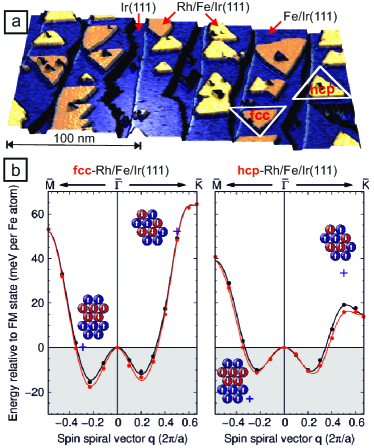
Including spin-orbit coupling (SOC), see red data in Fig. 1(b), leads to a preference of right rotating cycloidal spin spirals due to DMI for both types of stacking of the Rh overlayer. However, the energy differences are relatively small compared to the depths of the spin spiral energy minima neglecting SOC.
Because a significant role of higher-order exchange interactions has been reported for the Fe/Rh Hardrat et al. (2009); Al-Zubi et al. (2011) and Fe/Ir Heinze et al. (2011) interfaces, we have also considered collinear -states along the high symmetry directions. These states are formed by the superposition of spin spirals and should be energetically degenerate with them within the Heisenberg model. Energy differences obtained within DFT indicate higher-order exchange contributions. For fcc-Rh we find that both -states have a higher energy compared to the respective spin spirals, and the magnetic ground state remains a spin spiral along [Fig. 1(b)]. For hcp-Rh we find that the -state along the direction is about 34 meV/Fe-atom higher than the FM state, however, the -state along the direction is by about 12 meV/Fe-atom lower in energy than the lowest spin spiral state [Fig. 1(b)].
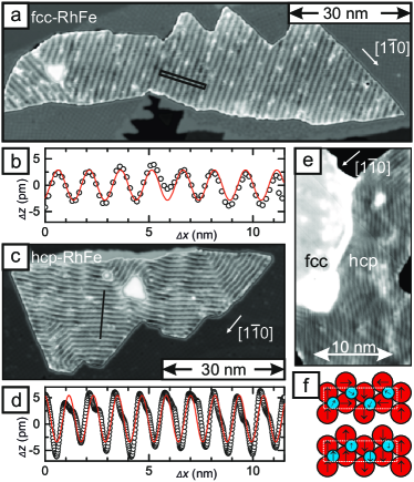
When a magnetic tip is used in STM the tunnel magnetoresistance (TMR) effect occurs, which leads to a SP contribution to the tunnel current in addition to the structural and electronic part Bode (2003); Wiesendanger (2009). Figure 2(a) shows such an SP-STM measurement of an fcc-Rh/Fe island exhibiting a cosine-like magnetic modulation with a period nm (see Fig. 2(b)) and propagation along directions. We conclude that fcc-Rh/Fe exhibits a spin spiral ground state with a continuous rotation of adjacent magnetic moments (see SI for further measurements), in agreement with the spin spiral energy minimum found along the direction from DFT (cf. Fig. 2(a)) spi .
The SP-STM image in Fig. 2(c) shows an hcp-Rh/Fe island and a similar stripe pattern with a slightly smaller period ( nm) is visible. The magnetic structure differs from the one in fcc-Rh/Fe islands in subtle aspects: the propagation direction seems to be more flexible, is not strictly along directions but instead varies locally; the shape of the periodic signal significantly differs from a cosine, compare profile in Fig. 2(d). This demonstrates that the magnetic ground state of the hcp-Rh/Fe island is different to that of fcc-Rh/Fe.
Because in STM several different magnetoresistive (MR) effects can contribute to the measurement signal Bode et al. (2002); Hanneken et al. (2015), in Fig. 2(e) we use a non-spin-polarized tip to separate purely electronic contributions from signal variations due to the TMR. We find that for fcc and hcp-Rh the TMR signals with periods of about nm and nm, respectively, vanish, meaning that they originate from TMR. On fcc-Rh on Fe/Ir(111) no remaining modulation of the signal is observed in the bias voltage regime V. In contrast, the non-spin-polarized signal observed on hcp-Rh is rather strong, i.e. on the order of a few pm, with half of the magnetic period, see Fig. 2(e), and can be observed in a bias voltage regime of around V.
Regarding the purely electronic contributions to magnetoresistance, the generic differences between a spin spiral and an -state, as predicted by DFT for our atomic Rh/Fe bilayer system, can be understood based on the sketches in Fig. 2(f). The tunnel anisotropic magnetoresistance (TAMR) Bode et al. (2002) due to spin-orbit coupling can occur for spin spirals (in-plane spins are inequivalent to out-of-plane spins) and would manifest as a modulation with half of the magnetic period, but it is absent in a collinear magnetic state as the -state. Regarding the non-collinear magnetoresistance Hanneken et al. (2015), the four-atom magnetic period is a special case where the contribution to the total magnetoresistance does not vary locally.
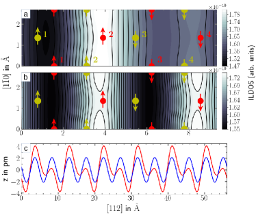
We can calculate STM images for the -state of hcp-Rh/Fe/Ir(111) directly from DFT. Within the Tersoff-Hamann model Tersoff and Hamann (1985) and its generalization to the spin-polarized case Wortmann et al. (2001) the STM image corresponds to the (spin-resolved) local density of states (LDOS) a few Å above the surface. The simulated SP-STM image [Fig. 3(a)] assuming a small negative bias voltage of 0.1 V shows a stripe pattern with the magnetic period corresponding to the -state. The scan lines display an asymmetric shape as seen in Fig. 3(c). If we assume a vanishing spin-polarization of the tip in our calculations we obtain the STM image in Fig. 3(b). We find a stripe pattern with half the magnetic period as in the experiment. As shown by the scan lines given in Fig. 3(c), the corrugation amplitude amounts to a few pm.
This electronic effect has been predicted before based on DFT for the -state in an Fe monolayer on Rh(111) Al-Zubi et al. (2011). For Rh/Fe/Ir(111) the effect is much enhanced as it originates from the interface with the Rh layer which is at the surface in our case. The -state can be viewed as the extreme limit of an inhomogeneous spin spiral, and the Rh atoms become inequivalent and have different magnetic moments depending on whether all three neighboring Fe atoms are parallel () or two are antiparallel and only one is parallel () (see sketch in Fig. 2f).
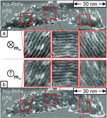
To investigate experimentally whether the hcp-Rh/Fe exhibits a strictly collinear magnetic ground state we image the out-of-plane and the in-plane magnetization components of the same island, see Fig. 4(a) and (b), respectively. This is done by using an Fe-coated W tip that aligns its magnetization in out-of-plane magnetic fields and thus detects out-of-plane sample magnetization components, whereas it has a magnetization in the surface plane without external magnetic field, thus being sensitive to the in-plane magnetization components of the sample. Figure 4(a) demonstrates that in measurements with an out-of-plane sensitive tip all three rotational domains appear the same; the pattern consists of slim bright lines spaced with the magnetic periodicity. Such a pattern is observed when the magnetic and the electronic MR contributions are of similar magnitude and in phase, i.e. the magnetic maxima/minima coincide with the maxima of the electronic contribution and thus add-up/cancel von Bergmann et al. (2012).
The SP-STM image with in-plane magnetized tip in Fig. 4(b) shows a qualitatively different pattern in the central rotational domain compared to the two other rotational domains. This immediately means that there are also magnetic in-plane components in the sample; given that the spin texture is of cycloidal nature due to the DMI, we can derive a tip magnetization axis as indicated, leading to a large magnetic contribution to the signal for the central domain. The magnetic signal is small in the other two domains and there the electronic contribution with half the magnetic period dominates the image. From these measurements we conclude that we have both out-of-plane as well as in-plane magnetization components in this sample and can thus rule out a strictly collinear state. However, because of the large electronic effect observed experimentally, which we attribute to the polarization variation of the Rh atoms, we propose that the hcp-Rh/Fe/Ir(111) realizes a magnetic state in between the two extreme cases of homogeneous spin spiral and (see Fig. 2(f)), i.e. an inhomogeneous spin spiral or a canted -state. Because the periodic modulation of the LDOS as manifested in the electronic contrast also changes the spin-polarization of the Rh atoms (see Fig. S6 SI ), we cannot quantitatively compare the measured magnetic amplitudes to extract the canting angle.
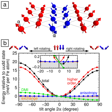
The DFT calculations of Fig. 1(b) have considered homogeneous spin spirals and collinear -states. To include inhomogeneous spin spirals, as found experimentally, and study which energy contributions could lead to such a state, we introduce a canting angle relative to the easy magnetization axis, see Fig. 5(a). This allows to continuously transform the -state () to the clockwise spin spiral (). Negative values of denote an anti-clockwise spin canting. It can easily be shown that the exchange energy contribution does not depend on . The magnetocrystalline anisotropy energy stabilizes the collinear state and varies as , however, the MAE is small with 0.53 meV/Fe-atom. The DMI favors a canting and decreases as for clockwise spin canting (Fig. 5(b)). Note that the strength of the DMI and the MAE are obtained from DFT. The energy difference of about 17 meV/Fe-atom between the and the spin spiral state can only be due to higher-order exchange contributions since spin-orbit coupling has been turned off in the DFT calculation. This leads to a rise with if we assume only nearest-neighbor four-spin and biquadratic interaction (see Eqs. (3) and (4) in SI ). The competition of DMI and these higher-order contributions leads to an energy minimum at a canting angle of between adjacent spins which are parallel in the collinear -state.
To check the validity of the spin model we have performed self-consistent non-collinear DFT calculations including spin-orbit coupling in the four atom per layer super cell of the state allowing the spins to relax to find the energetically most favorable state Kurz et al. (2004). To make these calculations computationally feasible, we have considered a freestanding Rh/Fe/Ir trilayer which is very similar to the Rh/Fe/Ir(111) film system in terms of its magnetic properties (see SI for details). We find a canted state with energetically more favorable by 0.03 meV/Fe-atom than the collinear -state. Two of the Rh magnetic moments point almost perpendicular to the surface while the other two are at angles of about with respect to the surface normal (see Fig. S4 SI ). Thus the in-plane components are enhanced at the Rh surface layer which explains the relatively strong in-plane contrast observed in SP-STM measurements (cf. Fig. S7 SI ).
In conclusion, we have shown that higher-order exchange interactions can play a decisive role in transition-metal trilayers and may compete with interfacial DM interactions. Our work demonstrates that higher-order exchange needs to be taken into account in the search for novel transition-metal interfaces potentially promising for complex non-collinear spin structures such as skyrmions.
Acknowledgements.
This work has received financial support by the European Union via the Horizon 2020 research and innovation programme under grant agreement No. 665095 (FET-Open project MagicSky), and by the Deutsche Forschungsgemeinschaft via SFB668-A8. We gratefully acknowledge computing time at the supercomputer of the North-German Supercomputing Alliance (HLRN).References
- Dzyaloshinskii (1957) I. E. Dzyaloshinskii, Sov. Phys. JETP 5, 1259 (1957).
- Moriya (1960) T. Moriya, Phys. Rev. 120, 91 (1960).
- Bogdanov and Yablonskii (1989) A. Bogdanov and D. A. Yablonskii, Sov. Phys. JETP 68, 101 (1989).
- Bogdanov and Hubert (1994) A. Bogdanov and A. Hubert, J. Mag. Mag. Mat. 138, 255 (1994).
- Bogdanov and Rößler (2001) A. N. Bogdanov and U. K. Rößler, Phys. Rev. Lett. 87, 037203 (2001).
- Mühlbauer et al. (2009) S. Mühlbauer, B. Binz, F. Jonietz, C. Pfleiderer, A. Rosch, A. Neubauer, R. Georgii, and P. Böni, Science 323, 915 (2009).
- Yu et al. (2010) X. Z. Yu, Y. Onose, N. Kanazawa, J. H. Park, J. H. Han, Y. Matsui, N. Nagaosa, and Y. Tokura, Nature 465, 901 (2010).
- Seki et al. (2012) S. Seki, X. Z. Yu, S. Ishiwata, and Y. Tokura, Science 336, 198 (2012).
- Fert et al. (2013) A. Fert, V. Cros, and J. Sampaio, Nat. Nanotechnol. 8, 152 (2013).
- Nagaosa and Tokura (2013) N. Nagaosa and Y. Tokura, Nat. Nanotechnol. 8, 899 (2013).
- Wiesendanger (2016) R. Wiesendanger, Nat. Rev. Mat. 1, 16044 (2016).
- Bode et al. (2007) M. Bode, M. Heide, K. von Bergmann, P. Ferriani, S. Heinze, G. Bihlmayer, a. Kubetzka, O. Pietzsch, S. Blügel, and R. Wiesendanger, Nature 447, 190 (2007).
- Ferriani et al. (2008) P. Ferriani, K. von Bergmann, E. Y. Vedmedenko, S. Heinze, M. Bode, M. Heide, G. Bihlmayer, S. Bluegel, and R. Wiesendanger, Phys. Rev. Lett. 101, 027201 (2008).
- Phark et al. (2014) S. H. Phark, J. A. Fischer, M. Corbetta, D. Sander, K. Nakamura, and J. Kirschner, Nat. Commun. 5, 5183 (2014).
- Kubetzka et al. (2003) A. Kubetzka, O. Pietzsch, M. Bode, and R. Wiesendanger, Phys. Rev. B 67, 020401 (2003).
- Heide et al. (2008) M. Heide, G. Bihlmayer, and S. Blügel, Phys. Rev. B 78, 140403 (2008).
- Meckler et al. (2009) S. Meckler, N. Mikuszeit, A. Pressler, E. Y. Vedmedenko, O. Pietzsch, and R. Wiesendanger, Phys. Rev. Lett. 103, 157201 (2009).
- Chen et al. (2013) G. Chen, J. Zhu, A. Quesada, J. Li, A. T. N’Diaye, Y. Huo, T. P. Ma, Y. Chen, H. Y. Kwon, C. Won, et al., Phys. Rev. Lett. 110, 177204 (2013).
- Emori et al. (2013) S. Emori, U. Bauer, S. Ahn, E. Martinez, and G. Beach, Nat. Mater. 12, 611 (2013).
- Ryu et al. (2013) K. Ryu, L. Thomas, S. Yang, and S. Parkin, Nat. Nanotechnol. 8, 527 (2013).
- Heinze et al. (2011) S. Heinze, K. von Bergmann, M. Menzel, J. Brede, A. Kubetzka, R. Wiesendanger, G. Bihlmayer, and S. Blügel, Nat. Phys. 7, 713 (2011).
- Romming et al. (2013) N. Romming, C. Hanneken, M. Menzel, J. E. Bickel, B. Wolter, K. von Bergmann, A. Kubetzka, and R. Wiesendanger, Science 341, 636 (2013).
- Romming et al. (2015) N. Romming, A. Kubetzka, C. Hanneken, K. von Bergmann, and R. Wiesendanger, Phys. Rev. Lett. 114, 177203 (2015).
- Chen et al. (2015) G. Chen, A. Mascaraque, A. T. N’Diaye, and A. K. Schmid, Appl. Phys. Lett. 106, 242404 (2015).
- Jiang et al. (2015) W. Jiang, P. Upadhyaya, W. Zhang, G. Yu, M. B. Jungfleisch, F. Y. Fradin, J. E. Pearson, Y. Tserkovnyak, K. L. Wang, O. Heinonen, et al., Science 349, 283 (2015).
- Hoffmann et al. (2015) M. Hoffmann, J. Weischenberg, B. Dupé, F. Freimuth, P. Ferriani, Y. Mokrousov, and S. Heinze, Phys. Rev. B 92, 020401(R) (2015).
- Boulle et al. (2016) O. Boulle, J. Vogel, H. Yang, S. Pizzini, D. de Souza Chaves, A. Locatelli, T. O. MenteÅŸ, A. Sala, L. D. Buda-Prejbeanu, O. Klein, et al., Nat. Nanotechnol. 11, 449 (2016).
- Moreau-Luchaire et al. (2016) C. Moreau-Luchaire, C. Moutafis, N. Reyren, J. Sampaio, C. A. F. Vaz, N. Van Horne, K. Bouzehouane, K. Garcia, C. Deranlot, P. Warnicke, et al., Nat. Nanotechnol. 11, 444 (2016).
- Woo et al. (2016) S. Woo, K. Litzius, B. Krüger, M.-Y. Im, L. Caretta, K. Richter, M. Mann, A. Krone, R. M. Reeve, M. Weigand, et al., Nat. Mater. 15, 501 (2016).
- Kurz et al. (2001) P. Kurz, G. Bihlmayer, K. Hirai, and S. Blügel, Phys. Rev. Lett. 86, 1106 (2001).
- Yoshida et al. (2012) Y. Yoshida, S. Schröder, P. Ferriani, D. Serrate, A. Kubetzka, K. von Bergmann, S. Heinze, and R. Wiesendanger, Phys. Rev. Lett. 108, 087205 (2012).
- Hardrat et al. (2009) B. Hardrat, A. Al-Zubi, P. Ferriani, S. Blügel, G. Bihlmayer, and S. Heinze, Phys. Rev. B 79, 094411 (2009).
- Al-Zubi et al. (2011) A. Al-Zubi, G. Bihlmayer, and S. Blügel, Phys. Status Solidi B 248, 2242 (2011).
- (34) Supplemental material.
- Bode (2003) M. Bode, Rep. Prog. Phys. 66, 523 (2003).
- Wiesendanger (2009) R. Wiesendanger, Rev. Mod. Phys. 81, 1495 (2009).
- (37) With an external magnetic field a skyrmion lattice phase can in principle be induced as shown by spin dynamics simulations (see SI ), however, due to the deep energy minimum the transition fields are about 50 T.
- Bode et al. (2002) M. Bode, S. Heinze, A. Kubetzka, O. Pietzsch, X. Nie, G. Bihlmayer, S. Blügel, and R. Wiesendanger, Phys. Rev. Lett. 89, 237205 (2002).
- Hanneken et al. (2015) C. Hanneken, F. Otte, A. Kubetzka, B. Dupé, N. Romming, K. von Bergmann, R. Wiesendanger, and S. Heinze, Nature Nanotech. 10, 1039 (2015).
- Tersoff and Hamann (1985) J. Tersoff and D. R. Hamann, Phys. Rev. B 31, 805 (1985).
- Wortmann et al. (2001) D. Wortmann, S. Heinze, P. Kurz, G. Bihlmayer, and S. Blügel, Phys. Rev. Lett. 86, 4132 (2001).
- von Bergmann et al. (2012) K. von Bergmann, M. Menzel, D. Serrate, Y. Yoshida, S. Schröder, P. Ferriani, A. Kubetzka, R. Wiesendanger, and S. Heinze, Phys. Rev. B 86, 134422 (2012).
- Kurz et al. (2004) P. Kurz, F. Förster, L. Nordström, G. Bihlmayer, and S. Blügel, Phys. Rev. B 69, 024415 (2004).