Mobility-limited polyarylamine biscarbonate ester (PABC) /[6,6]-phenyl butyric acid methyl ester (PCBM) bulk heterojunction photovoltaic device
Abstract
Photovoltaic (PV) devices made from blends of a polyarylamine biscarbonate ester (PABC) and [6,6]-phenyl butyric acid methyl ester (PCBM) have been fabricated and characterized. PABC is a hole transporting co-polymer prepared from reacting N,N’diphenyl-N,N’bis(3-hydroxyphenyl)1,1;biphenyl(4,4’diamine), diethylene glycol bischloroformate, and triethylemine. By varying the polymer loading in the blend, optimal power conversion efficiency (PCE) of approximately 0.45% has been achieved for a blend consisting of 25 wt% PABC, which is an order of magnitude higher than the PCE for a 45 wt% blend. The optimal ratio is at about 0.44:0.56 molar ratio of the active hole transporting to electron transporting moieties. Results of mobility studies suggest that blends with higher PABC loading have efficiencies limited by ’hole’ transport. Also responsible for the lower efficiency at higher PABC concentrations was optical filtering. The efficiency does not appear to be limited by deep charge trapping. Density functional theory calculations conducted pointed toward a strong localization of the frontier orbitals, which might offer an explanation for the low PABC hole mobility. Calculated frontier orbital energy levels found band gap to be consistent with the measured.
Introduction In the race to obtain the best performing organic solar materials, hundreds of materials, blends and configurations have been intensively studied by various groups li2012polymer ; li2012molecular ; dou2012tandem . However, the most efficient single layer organic solar cells still have efficiencies typically below 12% in laboratory conditions and significantly lower efficiencies in pilot production heeger201425th . Therefore, there is a continued need for research in all aspects of polymer photovoltaics such as materials chemistry, materials characterization, device physics, process and production technology. In particular, root cause identification of photovoltaic efficiency limitation is very relevant for further development of solar cells technologies. The most well-known organic photovoltaics are polymer-fullerene bulk heterojunction (BHJ) devices heeger201425th ; dennler2009polymer , where the polymer is the hole-transport material and the fullerene is the electron-transporting material. Among BHJ photovoltaic devices, the most well studied and most successful one, with efficiencies exceeding 5%, is the P3HT:PCBM blend, where the hole-transporting material is represented by poly(3-hexylthiophene) (P3HT) and the electron-transporting material is represented by 1-3(-methoxycarbonyl)propyl-1-phenyl[6-6] (PCBM). A first step when testing a combination of photovoltaic materials is to establish the optimum ratio of the materials for maximum power conversion efficiency. To achieve high power conversion efficiencies it is necessary to maximize the mobility of the charge carriers and to equalize as much as possible the mobility of the electrons in the electron transport material with the mobility of holes in the hole-transport material brabec2008organic . Power conversion efficiency is also highly dependent on the nano-morphology moule2006effect that depends on factors such as the solvent type, solvent evaporation rate, temperatures used during the fabrication process and deposition method gunes2007conjugated ; sobkowicz2011effect ; chen2012efficient . Most organic solar active materials require post-coating thermal and/or vacuum treatments, as well as additional buffer or blocking layers in their structure to prevent leakage or to facilitate photovoltaic effects rait2007effect ; zhao2010metal . It would be desirable to develop new photovoltaic devices with materials that support longer storage life and can be fabricated in ambient environment. From the theoretical standpoint, density functional theory (DFT) has been widely used to calculate, among other electronic properties of interest for photovoltaics, the frontier orbital energy levelsZhang2007 ; McCormick2013 ; Kozycz2012 ; Ayoub2015 ; Hu2015 and their spatial distribution zhou2012rational ; Kanai2007 ; Fu2015 . Despite there being some discussion with respect to the meaning of Kohn-Sham orbitals obtained from DFT, they are thought to be adequate for qualitative studies (see Stowasser et al Stowasser1999 and references therein). In this study, polyarylamine biscarbonate ester (PABC) - a hole-transporting material - was blended with PCBM (electron transporting material) in various ratios to produce solution-processed solar cells. We have investigated the effect of PABC:PCBM blend composition on the power conversion efficiency by examining the I-V curve under standard illumination. We have also studied carrier mobility of the materials and blends using the photoconductive time-of-flight (TOF) technique lin1998transient ; lin2000charge . PABC was originally produced for use as a stand-alone hole transporting polymeric material for photoconductors or photoreceptors in xerographic applicationsborsenberger1998organic . The molar ratio of the hole transporting moiety-arylamine-to that of carbonate ester moiety is about 62:38. One of the potential advantages of use of PABC is its long shelf life of over ten years, in contrast with shelf life of polythiophenes, such as P3HT, whose typical storage life is less than 18 months. In contrast to most photovoltaic materials that are highly oxygen sensitive, PABC layers can be in principle fabricated in ambient environments. No electron-blocking layer was necessary to reach photovoltaic activity; however to increase PEC by a factor of approximately 3 we have used PEDOT:PSS as an electron-blocking layer in most of the results reported in this paper. The structure of the device studied is Glass/ITO/ /PEDOT:PSS/PABC:PCBM/Al. DTF calculations were used to study energy levels, and to explain open circuit voltage and short circuit current for the PABC:PCBM blend. Calculations were checked against analogous calculations using the P3HT:PCBM blend.
Materials and Methods
Materials and PABC:PCBM Solution Preparation
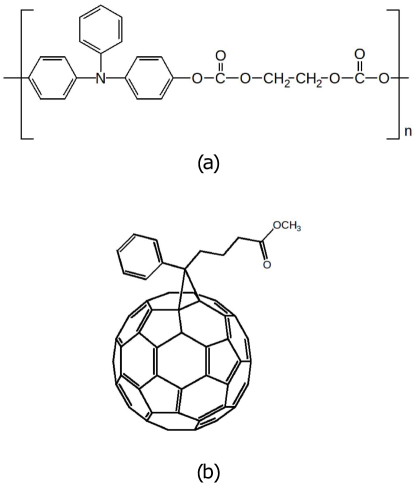
PABC is a co-polymer prepared from reacting N,N’diphenyl-N,N’bis(3hydroxyphenyl)1, 1;biphenyl(4,4’ diamine) (DNTBD), diethylene glycol bischloroformate, and triethylemine. The PABC molecular structure is shown in Fig. 1(a). The PABC was produced by Xerox Corporation. PCBM powder was purchased from American Dye Source. The PCBM molecular structure is shown in Fig. 1(b). Each material was dissolved in monochlorobenzene and the solution was left overnight. Eight different wt% of PABC were examined: 5, 15, 20, 25, 30, 35, 40, and 45 wt%. In this paper, all usage of wt% refers to the mass percentage of PABC as a fraction of the total mass of solids in the solution, with the remainder of the solid being PCBM. The combined 2 wt% solutions in the array of PABC:PCBM ratios were mixed in a bath sonicator for 20 minutes and heated to 60∘C for 10 minutes. Each solution was filtered using a 1.0m pore-size syringe filter. PEDOT:PSS, an electrically conductive polymer blend with hole-transporting characteristics that consists of poly(3,4-ethylenedioxythiphene)polycation and a poly(styrenesulfonate)polyanion, was ordered from Sigma Aldrich (150 S/cm at 18 m film thickness). Indium-tin-oxide (ITO) coated aluminosilicate glass substrates were purchased from Delta Technologies (1” x 1”, 85% transmittance, 120-160 nm coating thickness, 15 Ohms/square).
 |
PABC:PCBM BHJ Solar Cell Fabrication
Instead of the conventional chemical etching the ITO substrates were laser etched to produce six isolated devices. The laser etching produces features under 50 m in width and about 0.15 m in depth – enough to completely remove the ITO, as confirmed electrical tests. This is a much faster process than the usual chemical etching of the ITO glass and was readily available in our facility. The laser etching lines as well as the regions where the materials are deposited are shown in Fig. 2(a)-(c). After laser etching the ITO glass samples were cleaned by ultrasonic bath in isopropyl alcohol.
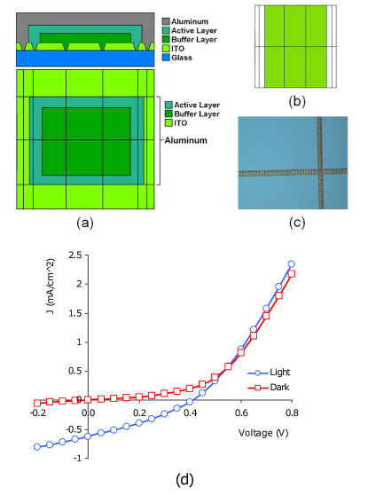 |
Each ITO substrate was etched to form six photovoltaic cells. The area of each cell is approximately 5 mm 5 mm. Scotch tape was used to mask the regions not to be coated during the spin coating processes and during the aluminum (cathode) deposition step. PEDOT:PSS was syringe-deposited onto the conveniently masked ITO, spin coated at 4000 rpm for 60 s and air dried to form a layer of about 30 nm thickness. The PABC:PCBM blend solutions were spin-coated at 1100 rpm for 60s onto the ITO coated glass substrates and air dried. The blend solutions were dried in place for 5 minutes to prevent the layer from being disturbed as the volatiles evaporated. The active layer was further annealed at 120∘C for about 15 minutes. The top aluminum contact was deposited by thermal evaporation (Edwards E306A vacuum coating unit) through a mask with aperture of 0.5 cm by 0.5 cm. Aluminum deposition pressure was torr . The thickness of the aluminum layer deposited was estimated to be of the order of 100 to 300 nm (barely translucid to room fluorescent light). Deposition time and current were kept constant throughout the various experiments. All processing, except Al deposition was performed at ambient air (RH ¡ 50%, temperature 22∘C). During spin coating, a glove box was used to assure that the ambient relative humidity (RH) was below 40%. Higher relative humidity gave a high rate of very low yield devices.
J-V Characterization
A solar simulator designed and built by Xerox Corporation and meeting the AM1.5G standard for class B was used as illumination source. The solar simulator spectral characteristics were verified in the 200-1100 nm range using a fiber spectrometer Ocean Optics model HR2000 and the light intensity was calibrated to 100 mW/cm2 using a thermopile detector Coherent PM3 (50 W power resolution). J-V characteristics of dark and illuminated solar cells were measured using a custom-made probe station in conjunction with a Keithley 237 voltage source-measuring unit. J-V data was collected with a Labview routine though the Keithley 237 GPIB. Spring-loaded probes purchased from Everett Charles Technologies were used for electrical contacts with the ITO coated surface region (anode) and with the deposited aluminum region (cathode), both at the same side of the ITO slide. The RC constant of each cell built was of the order of 1 s. The scan speed for the J-V curve was chosen such that the dwell time for acquisition of each point was 10 ms or longer to ensure steady state measurements. All measurements were performed within two hours of device fabrication.
Time-of-flight measurements
Samples were prepared by bar coating of solution mixtures of the PABC polymer on a pre-coated charge-generating layer consisted of a phthalocyanine on a metalized polyethylene terephthalate substrate. After drying at 120∘C for about 5 minutes and cooling down to room temperature a gold electrode was deposited on the films. The film thickness was about 5-15 m as measured by an eddy current thickness gauge. Reference devices were also prepared by using mixtures of TPD and polycarbonate (PC) at various weight ratios. TPD is a hole transport molecule N,N’-diphenyl-N,N’-bis(3-methylphenyl)-[1,1’-biphenyl]-4,4’-diamine (TPD) described in reference khan2004morphological .Charge mobility was measured in ambient conditions by conventional time-of-flight techniquenam2009high .
Light pulses were obtained from a nitrogen laser (Spectra Physics) pumped red dye at 680 nm, 10 ns pulse, 10 Hz repetition rate. The bias of the cells was negative at the Au electrode for hole-transport studies. Reverse biases were also applied to investigate leakage and presence of contaminants. Data was collected at field strengths of about to V/cm. To maintain a constant field during the period of photocurrent transients, the number of injected charges was kept at less than 5% of the capacitive charges by using neutral density filters in the laser beam. The transit time was determined from the intersection of tangents drawn in linear plots before and after the downturn of the photocurrent transientsabkowitz1998direct .
Results and Discussion
The PABC:PCBM solution showed good film forming properties at various weight ratios (5 to 45% of PABC). A typical J-V curve is shown in Fig. 2(d). When in dark conditions, the typical diode behavior is shown. For an illumination of 100 mW/cm2 the photoelectric activity can be observed by the presence of a current density at zero applied voltage. Fig 3, shows the power conversion efficiency as a function of the amount of PABC (wt%). The highest efficiency achieved without a buffer layer was 0.12%, for a device having an active layer with 25 wt% PABC and 75 wt% PCBM. The efficiency at the same concentrations jumped to 0.45% with the use of a PEDOT:PSS buffer layer in the position indicated in Fig. 2(a). When the amount of PABC was increased to 30 wt%, the efficiency decreased to about 0.32%. Further increases in the amount of PABC resulted in devices exhibiting an even lower efficiency: 0.05% efficiency at 35 wt% PABC and relatively negligible efficiency at 40 and 45 wt% PABC.
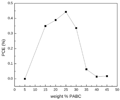 |
Table 1 summarizes the photovoltaic characteristics obtained as a function of PABC concentration, where JSC is the short-circuit current density, Voc is the open circuit voltage, FF is the fill factor and PCE is the power conversion efficiency.
| PABC wt(%) | JSC(mAcm-2) | VOC(V) | FF | PCE(%) |
|---|---|---|---|---|
| 0.00 | 0.00 | 0.00 | 0.00 | |
| 0.73 | 0.24 | 0.28 | 0.35 | |
| 0.75 | 0.26 | 0.27 | 0.39 | |
| 0.69 | 0.32 | 0.27 | 0.45 | |
| 0.56 | 0.30 | 0.30 | 0.34 | |
| 0.25 | 0.13 | 0.29 | 0.06 | |
| 0.13 | 0.06 | 0.26 | 0.01 | |
| 0.13 | 0.07 | 0.27 | 0.02 |
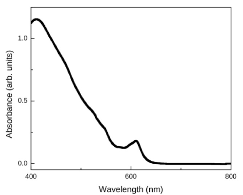
We have performed further studies to understand the origins of the efficiency limitation of the PABC:PCBM BHJ solar cell. Fig 4 shows the absorption spectrum for PABC:PCBM at 25:75. The low efficiency of the PABC/PCBM solar cells can be partially attributed to the predominantly blue visible light absorption of PABC.
 |
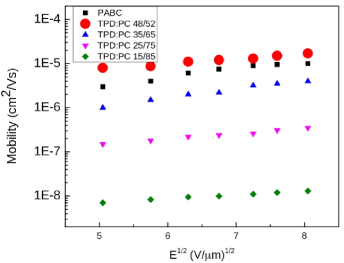
In order to understand the role of PABC charge mobility in the determination of the optimum PABC:PCBM ratio and overall PCE, we have performed time of flight experiments. We have used pure PABC films and, for comparison, TPD doped polycarbonate (PC) films, both prepared as previously described. In our photovoltaic studies TPD did not show any appreciable photovoltaic activity when in combination with PCBM at various blending ratios. However, TPD is a well-known hole-transporting molecule with similar molecular moiety to that of PABC and was used for comparison purposes. Fig 5 shows the results of our time-of-flight experiments. It was found that the charge transport behaviors of PABC are non-dispersive with a similar field dependency as that of TPD and its charge mobility is comparable to 40-55 wt% TPD doped PC, suggesting a trap-free hopping charge transport behavior. The charge mobility of PABC is somewhat lower than that of TPD/polycarbonate blend at the similar molar ratio, about 62:38, which is attributed to molecular structure confinement of the hole transporting polymer in contrast to molecularly doped polymers like the TPD/polycarbonate blend. The charge mobility of PABC is nevertheless one of the higher linear chain hole transporting polymers with charge transporting moiety resides in the linear polymer chain. However large in relative terms, mobilities of the order or cm2/Vs fall short of the range necessary to produce high fill factors in the solar cells. Using parameters for P3HT:PCBM (1:1), Deibel et aldeibel2008influence and Ramirez et alramirez2014optimum demonstrate theoretically the existence of an optimum electron mobility value of about cm2/Vs to 1 cm2/Vs with a logarithmic degradation of PEC as mobility moves away from the optimum value. When the hole mobility falls from 1 cm2/Vs to cm2/Vs, PEC drops by about factor of ten. This could be part of the explanation of the low PEC of the PABC:PCBM solar cell.
 |
The optimum experimentally found blend ratio for PABC: PCBM is 1 : 3 while the optimum blend for P3HT:PCBM is approximatelydennler2009polymer 1 : 1. This might be explained by the difference in relative mobility of electrons and holes in the blend. The molecular mass of the repeating unit in PABC is 390, where 242 is attributed to arylamine, hole transporting moiety, and 148 to PABC’s biscarbonate ester component. The molecular mass of PCBM is 911, so the molar ratio for the optimum blend ratio of PABC:PCBM is or about 1.3 : 1. This contrasts with the 5.5 : 1 molar ratio for the optimum blend for the P3HT:PCBM system dennler2009polymer . The PABC:PCBM system requires a significantly smaller amount of hole transporting units to reach a balance in electron to hole mobility. It is well known that the highest power conversion efficiency is reached when there is a balance in the electron to hole mobility rationakamura2005relation ; ramirez2014optimum . Low mobility combined with steady currents frequently lead to space-charge limited current (SCLC)zhang2012theory . In SCLC trapped charges accumulate in the bulk of the device creating a field that reduces throughput. However, observation of a Log-Log plot of the I-V curve for a PABC:PCBM in the dark suggested that in our devices the traps are shallow and should not be the main efficiency limiting mechanism. When comparing our devices’ J-V curve with that of other materials, as compiled by Zhou et alzhou2012rational , we see that while PABC grants a typical value for , it falls an order of magnitude short on the aspect of , which we recognize as the limiting factor on PCE. Despite the fact that is essentially a macroscopic observable heavily dependent on the morphology, we decided to apply electronic structure methods to clarify some of its characteristics. In fact, electronic structure studies are regularly used in the context of organic photovoltaics to link variables of very different scales. As one example, Fu et alfu2014structure have calculated the transfer integrals describing exciton dissociation rates in a model OPV bilayer. These dissociation rates can be readily measured and are the main source of photogenerated charge carriers. As summarized by Lili2012molecular , it is accepted that is proportional to the gap between the donor HOMO and acceptor LUMO. To investigate it, we have calculated the frontier levels of the PABC and PCBM molecules, as well as P3HT as a standard for comparison. For computational reasons, in this work we chose to approximate the PABC polymer by a three-unit long olygomer, and P3HT as a six-unit long olygomer. The results can be seen in Fig 6.
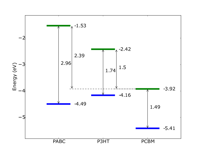 |
As we can see, the PABC:PCBM blend has a larger gap than the P3HT:PCBM blend, which supports our experimental result of typical for our material. This is consistent with our predicted difference between donor and acceptor LUMO, which is larger than the eV that the literature usually recognizes as being necessary for good charge separation (see for example Zhou et alzhou2012rational ). To locate the origin of the limitation of , we plotted the frontier orbitals for a series of increasingly long PABC oligomers, and compared them to the frontier orbitals of a six-unit long P3HT oligomer. It can be seen that while the frontier orbitals for P3HT spread along the full span of the polymer, following the bond backbone as typical of most polymer organic semiconductors, Fig 7, the frontier orbitals of the PABC polymer form a slightly more complicated picture.
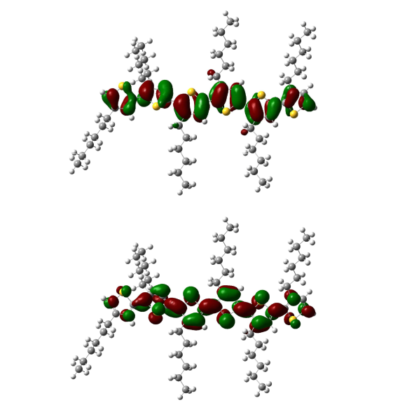 |
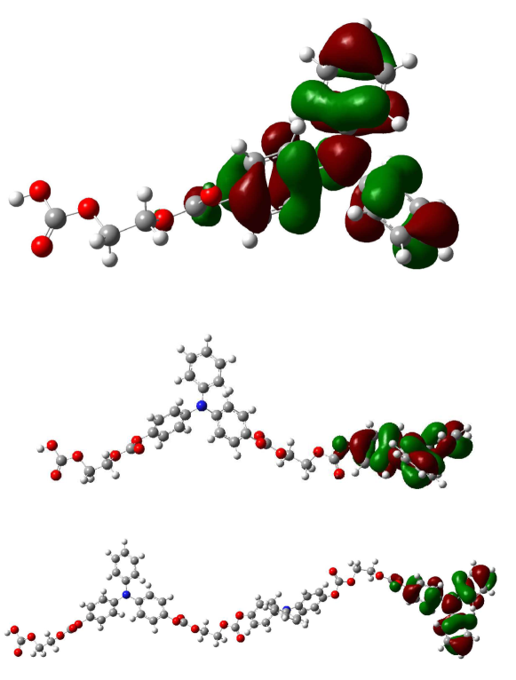
The highest occupied molecular orbitals form a degenerate set of orbitals localized on individual monomer sites. In fact, these frontier orbitals present almost no deformation by the presence of neighbours; they have the same shape as the one calculated for the isolated monomer, see Fig 8. The same is true for the lowest unoccupied molecular orbitals, see Fig 9.
 |
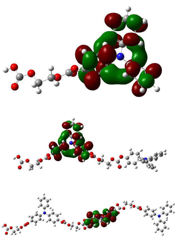 |
However, degeneracy implies that a linear combination over each set of frontier orbitals can also be understood as a real orbital. Therefore, one can construct a frontier orbital delocalized over the donor polymer sites, which provides a mechanism for charge transport. Nonetheless, even these resulting orbitals, localized over all donor sites, are more localized than those of the P3HT HOMO and LUMO, as the later is fully delocalized over the entire conjugated backbone. The localization observed in PABC will result in less mobile excitations in this polymer when compared to the equivalent excitations in P3HT, and hence this effect could be seen as the hindering factor for excitation transfer between PABC molecules, limiting the charge transport and being the most likely cause for the low observed in experiment. The frontier orbital DFT calculations were done following geometry optimization, using the B97D functionalgrimme2006semiempirical , with basis 6-311g**. All calculations were done using Gaussian 09g09 software package. Efficiency could have an incremental improvement with better ITO conductivity. A P-type oxide semiconductor such as NiO could be used to coat the ITO to increase efficiency by appropriately matching the energy levelsirwin2008p . Analogously, an n-type semiconductor such as LiF can be used to coat the Al electrode to increase efficiencyhains2007bulk . Another opportunity is the optimization of device thickness that is known to increase efficiency both due to recombination and to optical interference issueshoppe2007inverse ; van2009relation . Strict control of the aluminum evaporation process is also relevant for the overall efficiency of the sample. If aluminum evaporation occurs faster than a critical rate, the combination of heat capacity and heat dissipation of the sample glass is not enough to keep the sample below 200∘C where thermal damage to the polymer starts to occur. All these factors are also related to the optimization of the morphology of the blendvan2010p3ht that is an art by itself and requires empirical design and trial and error.
Conclusion
In summary, photovoltaic response was observed with a hole transporting polymer polyarylamine biscarbonate ester (PABC) blended with PCBM as the electron transporting material, in the bulk heterojunction configuration. Efficiencies without further optimization were of the order of 0.5%. Our results suggested that the low efficiencies are due to low PCBM mobility for the technique used.
The experimental part of this work has been disclosed at US Patent 8,975,511 by LBL, GCC, AEP and KB. DASF acknowledges the financial support from the Brazilian Research Council CNPq, grants 306968/2013-4 and 407682/2013-9, and FAP-DF grant 0193.001.062/2015. AAM and G.C.C. acknowledge financial support from the Brazilian Federal Agency for Support and Evaluation of Graduate Education (CAPES) within the Ministry of Education of Brazil and CAPES/Programa Ciencia sem Fronteiras.
References
- (1) Li G, Zhu R, Yang Y. Polymer solar cells. Nature Photonics. 2012;6(3):153–161.
- (2) Li Y. Molecular design of photovoltaic materials for polymer solar cells: toward suitable electronic energy levels and broad absorption. Accounts of Chemical Research. 2012;45(5):723–733.
- (3) Dou L, You J, Yang J, Chen CC, He Y, Murase S, et al. Tandem polymer solar cells featuring a spectrally matched low-bandgap polymer. Nature Photonics. 2012;6(3):180–185.
- (4) Heeger AJ. 25th anniversary article: bulk heterojunction solar cells: understanding the mechanism of operation. Advanced Materials. 2014;26(1):10–28.
- (5) Dennler G, Scharber MC, Brabec CJ. Polymer-Fullerene bulk-heterojunction solar cells. Advanced Materials. 2009;21(13):1323–1338.
- (6) Brabec C, Scherf U, Dyakonov V. Organic photovoltaics: materials, device physics, and manufacturing technologies. John Wiley & Sons; 2008.
- (7) Moulé AJ, Bonekamp JB, Meerholz K. The effect of active layer thickness and composition on the performance of bulk-heterojunction solar cells. Journal of applied physics. 2006;100(9):094503.
- (8) Günes S, Neugebauer H, Sariciftci NS. Conjugated polymer-based organic solar cells. Chemical reviews. 2007;107(4):1324–1338.
- (9) Sobkowicz MJ, Jones RL, Kline RJ, DeLongchamp DM. Effect of fullerenes on crystallization-induced aggregation in polymer photovoltaics casting solutions. Macromolecules. 2011;45(2):1046–1055.
- (10) Chen L, Wang P, Li F, Yu S, Chen Y. Efficient bulk heterojunction polymer solar cells using PEDOT/PSS doped with solution-processed MoO 3 as anode buffer layer. Solar Energy Materials and Solar Cells. 2012;102:66–70.
- (11) Rait S, Kashyap S, Bhatnagar P, Mathur P, Sengupta SK, Kumar J. Effect of a buffer layer, composition and annealing on the performance of a bulk heterojunction polythiophene/fullerene composite photovoltaic device. Physica E: Low-dimensional Systems and Nanostructures. 2007;39(2):191–197.
- (12) Zhao Z, Teki R, Koratkar N, Efstathiadis H, Haldar P. Metal oxide buffer layer for improving performance of polymer solar cells. Applied Surface Science. 2010;256(20):6053–6056.
- (13) Zhang G, Musgrave CB. Comparison of DFT methods for molecular orbital eigenvalue calculations. The Journal of Physical Chemistry A. 2007;111(8):1554–1561.
- (14) McCormick TM, Bridges CR, Carrera EI, DiCarmine PM, Gibson GL, Hollinger J, et al. Conjugated polymers: Evaluating DFT methods for more accurate orbital energy modeling. Macromolecules. 2013;46(10):3879–3886.
- (15) Kozycz LM, Gao D, Hollinger J, Seferos DS. Donor–donor block copolymers for ternary organic solar cells. Macromolecules. 2012;45(14):5823–5832.
- (16) Ayoub SA, Lagowski JB. Optimizing the Performance of Multilayered Organic Polymer Devices Using Computational Dimer Approach–A Case Study. The Journal of Physical Chemistry C. 2015;120(1):496–507.
- (17) Hu H, Jiang K, Yang G, Liu J, Li Z, Lin H, et al. Terthiophene-based D–A polymer with an asymmetric arrangement of alkyl chains that enables efficient polymer solar cells. Journal of the American Chemical Society. 2015;137(44):14149–14157.
- (18) Zhou H, Yang L, You W. Rational design of high performance conjugated polymers for organic solar cells. Macromolecules. 2012;45(2):607–632.
- (19) Kanai Y, Grossman JC. Insights on interfacial charge transfer across P3HT/fullerene photovoltaic heterojunction from ab initio calculations. Nano letters. 2007;7(7):1967–1972.
- (20) Fu G, Wang T, Cai J, Shi J, Luo Z, Li G, et al. Formation of charge transfer complexes significantly improves the electron transfer process of polymer solar cells. Organic Electronics. 2015;18:70–76.
- (21) Stowasser R, Hoffmann R. What do the Kohn-Sham orbitals and eigenvalues mean? Journal of the american chemical society. 1999;121(14):3414–3420.
- (22) Lin LB, Young R, Mason M, Jenekhe S, Borsenberger P. Transient photocurrents across organic–organic interfaces. Applied physics letters. 1998;72(7):864–866.
- (23) Lin LB, O’Reilly JM, Magin EH, Weiss DS, Jenekhe SA. Charge transport in tri-p-tolylamine doped trinaphthalylbenzene glass. Journal of Applied Physics. 2000;88(6):3501–3505.
- (24) Borsenberger PM. Organic photoreceptors for xerography. vol. 59. CRC Press; 1998.
- (25) Khan F, Hor AM, Sundararajan P. Morphological reasoning for the enhanced charge carrier mobility of a hole transport molecule in polystyrene. Pure and applied chemistry. 2004;76(7-8):1509–1520.
- (26) Nam CY, Su D, Black CT. High-Performance Air-Processed Polymer–Fullerene Bulk Heterojunction Solar Cells. Advanced Functional Materials. 2009;19(22):3552–3559.
- (27) Abkowitz M, Facci J, Rehm J. Direct evaluation of contact injection efficiency into small molecule based transport layers: Influence of extrinsic factors. Journal of applied physics. 1998;83(5):2670–2676.
- (28) Deibel C, Wagenpfahl A, Dyakonov V. Influence of charge carrier mobility on the performance of organic solar cells. physica status solidi (RRL)-Rapid Research Letters. 2008;2(4):175–177.
- (29) Ramírez O, Cabrera V, Reséndiz LM. Optimum ratio of electron-to-hole mobility in P3HT: PCBM organic solar cells. Optical and Quantum Electronics. 2014;46(10):1291–1296.
- (30) Nakamura Ji, Murata K, Takahashi K. Relation between carrier mobility and cell performance in bulk heterojunction solar cells consisting of soluble polythiophene and fullerene derivatives. Applied Physics Letters. 2005;87(13):132105.
- (31) Zhang XG, Pantelides ST. Theory of space charge limited currents. Physical review letters. 2012;108(26):266602.
- (32) Fu YT, da Silva Filho DA, Sini G, Asiri AM, Aziz SG, Risko C, et al. Structure and disorder in squaraine–C60 organic solar cells: a theoretical description of molecular packing and electronic coupling at the donor–acceptor interface. Advanced Functional Materials. 2014;24(24):3790–3798.
- (33) Grimme S. Semiempirical GGA-type density functional constructed with a long-range dispersion correction. Journal of computational chemistry. 2006;27(15):1787–1799.
- (34) Frisch MJ, Trucks GW, Schlegel HB, Scuseria GE, Robb MA, Cheeseman JR, et al.. Gaussian 09 Revision C.01;. Gaussian Inc. Wallingford CT 2009.
- (35) Irwin MD, Buchholz DB, Hains AW, Chang RP, Marks TJ. p-Type semiconducting nickel oxide as an efficiency-enhancing anode interfacial layer in polymer bulk-heterojunction solar cells. Proceedings of the National Academy of Sciences. 2008;105(8):2783–2787.
- (36) Hains A, Martinson A, Irwin M, Yan H, Marks T. Bulk-heterojunction organic solar cells: Interfacial engineering routes to increased open-circuit voltage and power conversion efficiency. Polym Mater Sci Eng. 2007;96:814–815.
- (37) Hoppe H, Shokhovets S, Gobsch G. Inverse relation between photocurrent and absorption layer thickness in polymer solar cells. physica status solidi (RRL)-Rapid Research Letters. 2007;1(1):R40–R42.
- (38) van Bavel S, Sourty E, de With G, Frolic K, Loos J. Relation between photoactive layer thickness, 3D morphology, and device performance in P3HT/PCBM bulk-heterojunction solar cells. Macromolecules. 2009;42(19):7396–7403.
- (39) Van Bavel SS, Bärenklau M, de With G, Hoppe H, Loos J. P3HT/PCBM bulk heterojunction solar cells: impact of blend composition and 3D morphology on device performance. Advanced Functional Materials. 2010;20(9):1458–1463.