Spin transport and dynamics in all-oxide perovskite La2/3Sr1/3MnO3/SrRuO3 bilayers probed by ferromagnetic resonance
Abstract
Thin films of perovskite oxides offer the possibility of combining emerging concepts of strongly correlated electron phenomena and spin current in magnetic devices. However, spin transport and magnetization dynamics in these complex oxide materials are not well understood. Here, we experimentally quantify spin transport parameters and magnetization damping in epitaxial perovskite ferromagnet/paramagnet bilayers of La2/3Sr1/3MnO3/SrRuO3 (LSMO/SRO) by broadband ferromagnetic resonance spectroscopy. From the SRO thickness dependence of Gilbert damping, we estimate a short spin diffusion length of 1 nm in SRO and an interfacial spin-mixing conductance comparable to other ferromagnet/paramagnetic-metal bilayers. Moreover, we find that anisotropic non-Gilbert damping due to two-magnon scattering also increases with the addition of SRO. Our results demonstrate LSMO/SRO as a spin-source/spin-sink system that may be a foundation for examining spin-current transport in various perovskite heterostructures.
I Introduction
Manipulation and transmission of information by spin current is a promising route toward energy-efficient memory and computation devices Stamps2014 . Such spintronic devices may consist of ferromagnets interfaced with nonmagnetic conductors that exhibit spin-Hall and related spin-orbit effects Hoffmann2013 ; Sinova2015 ; Hoffmann2015a . The direct spin-Hall effect in the conductor can convert a charge current to a spin current, which exerts torques on the adjacent magnetization and modifies the state of the device Brataas2012 ; Locatelli2014 . Conversely, the inverse spin-Hall effect in the conductor can convert a propagating spin current in the magnetic medium to an electric signal to read spin-based information packets Chumak2015 . For these device schemes, it is essential to understand the transmission of spin current between the ferromagnet and the conductor, which is parameterized by the spin-mixing conductance and spin diffusion length. These spin transport parameters can be estimated by spin pumping at ferromagnetic resonance (FMR), in which a spin current is resonantly generated in the ferromagnet and absorbed in the adjacent conductor Tserkovnyak2002a ; Tserkovnyak2002 . Spin pumping has been demonstrated in various combinations of materials, where the magnetic layer may be an alloy (e.g., permalloy) or insulator (e.g., yttrium iron garnet) and the nonmagnetic conductor may be a transition metal, semiconductor, conductive polymer, or topological insulator Czeschka2011 ; Sun2013 ; Zhang2015a ; Du2015 ; Ando2011a ; Ando2013 ; Jamali2015 .
Transition metal oxides, particularly those with the perovskite structure, offer the intriguing prospect of integrating a wide variety of strongly correlated electron phenomena Zubko2011 ; Hwang2012 with spintronic functionalities Majumdar2014 ; Lesne2016 . Among these complex oxides, La2/3Sr1/3MnO3 (LSMO) and SrRuO3 (SRO) are attractive materials for epitaxial, lattice-matched spin-source/spin-sink heterostructures. LSMO, a metallic ferromagnet known for its colossal magnetoresistance and Curie temperature of 300 K, can be an excellent resonantly-excited spin source because of its low magnetization damping Luo2013 ; Luo2015 ; Lee2016 ; Haidar2015 ; Atsarkin2016 ; Wahler2016 . SRO, a room-temperature metallic paramagnet with relatively high conductivity Koster2012 , exhibits strong spin-orbit coupling Langner2009 that may be useful for emerging spintronic applications that leverage spin-orbit effects Hoffmann2013 ; Sinova2015 ; Hoffmann2015a .
A few recent studies have reported dc voltages at FMR in LSMO/SRO bilayers that are attributed to the inverse spin-Hall effect in SRO generated by spin pumping Haidar2015 ; Atsarkin2016 ; Wahler2016 . However, it is generally a challenge to separate the inverse spin-Hall signal from the spin rectification signal, which is caused by an oscillating magnetoresistance mixing with a microwave current in the conductive magnetic layer Azevedo2011 ; Bai2013 ; Obstbaum2014 . Moreover, while the spin-mixing conductance is typically estimated from the enhancement in the Gilbert damping parameter , the quantification of is not necessarily straightforward in epitaxial thin films that exhibit pronounced anisotropic non-Gilbert damping Lindner2003a ; Woltersdorf2004a ; Lenz2006 ; Zakeri2007a ; Barsukov2011 ; Kurebayashi2013 ; Lee2016 . It has also been unclear how the Gilbert and non-Gilbert components of damping in LSMO are each modified by an adjacent SRO layer. These points above highlight the need for an alternative experimental approach for characterizing spin transport and magnetization dynamics in LSMO/SRO.
In this work, we quantify spin transport parameters and magnetization damping in epitaxial LSMO/SRO bilayers by broadband FMR spectroscopy with out-of-plane and in-plane external magnetic fields. Out-of-plane FMR enables straightforward extraction of Gilbert damping as a function of SRO overlayer thickness, which is reproduced by a simple “spin circuit” model based on diffusive spin transport Boone2013 ; Boone2015 . We find that the spin-mixing conductance at the LSMO/SRO interface is comparable to other ferromagnet/conductor interfaces and that spin current is absorbed within a short length scale of 1 nm in the conductive SRO layer. From in-plane FMR, we observe pronounced non-Gilbert damping that is anisotropic and scales nonlinearly with excitation frequency, which is accounted for by an existing model of two-magnon scattering Arias1999 . This two-magnon scattering is also enhanced with the addition of the SRO overlayer possibly due to spin pumping. Our findings reveal key features of spin dynamics and transport in the prototypical perovskite ferromagnet/conductor bilayer of LSMO/SRO and provide a foundation for future all-oxide spintronic devices.
II Sample and Experimental Details
Epitaxial films of LSMO(/SRO) were grown on as-received (001)-oriented single-crystal (LaAlO3)0.3 (Sr2AlTaO6)0.7 (LSAT) substrates using pulsed laser deposition. LSAT exhibits a lower dielectric constant than the commonly used SrTiO3 substrate and is therefore better suited for high-frequency FMR measurements. The lattice parameter of LSAT (3.87 Å) is also closely matched to the pseudocubic lattice parameter of LSMO (3.88 Å). By using deposition parameters similar to those in previous studies from our group Takamura2008 ; Grutter2010 , all films were deposited at a substrate temperature of 750 ∘C with a target-to-substrate separation of 75 mm, laser fluence of 1 J/cm2, and repetition rate of 1 Hz. LSMO was deposited in 320 mTorr O2, followed by SRO in 100 mTorr O2. After deposition, the samples were held at 600 ∘C for 15 minutes in 150 Torr O2 and then the substrate heater was switched off to cool to room temperature. The deposition rates were calibrated by x-ray reflectivity measurements. The thickness of LSMO, , in this study is fixed at 10 nm, which is close to the minimum thickness at which the near-bulk saturation magnetization can be attained.
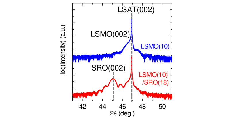
X-ray diffraction results indicate that both the LSMO films and LSMO/SRO bilayers are highly crystalline and epitaxial with the LSAT(001) substrate, with high-resolution 2- scans showing distinct Laue fringes around the (002) Bragg reflection (Fig. 1). In this study, the maximum thickness of the LSMO and SRO layers combined is less than 30 nm and below the threshold thickness for the onset of structural relaxation by misfit dislocation formation Takamura2008 ; Grutter2010 . The typical surface roughness of LSMO and SRO measured by atomic force microscopy is 4 Å, comparable to the roughness of the LSAT substrate surface.
SQUID magnetometry confirms that the Curie temperature of the LSMO layer is 350 K and the room-temperature saturation magnetization is kA/m for 10-nm thick LSMO films. The small LSMO thickness is desirable for maximizing the spin-pumping-induced enhancement in damping, since spin pumping scales inversely with the ferromagnetic layer thickness Tserkovnyak2002a ; Tserkovnyak2002 . Moreover, the thickness of 10 nm is within a factor of 2 of the characteristic exchange length nm, assuming an exchange constant of pJ/m in LSMO (Ref. (43)), so standing spin-wave modes are not expected.
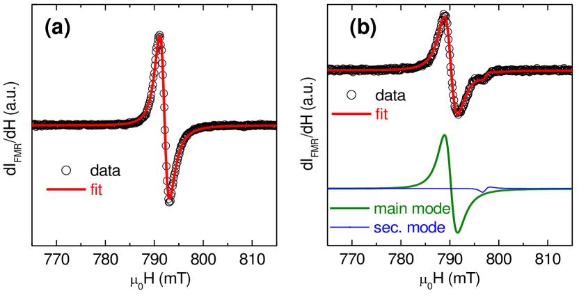
Broadband FMR measurements were performed at room temperature. The film sample was placed face-down on a coplanar waveguide with a center conductor width of 250 m. Each FMR spectrum was acquired at a constant excitation frequency while sweeping the external magnetic field . The field derivative of the FMR absorption intensity (e.g., Fig. 2) was acquired using an rf diode combined with an ac (700 Hz) modulation field. Each FMR spectrum was fitted with the derivative of the sum of the symmetric and antisymmetric Lorentzians, as shown in Fig. 2, from which the resonance field and half-width-at-half-maximum linewidth were extracted. In some spectra (e.g., Fig. 2(b)), a small secondary mode in addition to the main FMR mode was observed. We fit such a spectrum to a superposition of two modes, each represented by a generalized Lorentzian derivative, and analyze only the and of the larger-amplitude main FMR mode. The secondary mode is not a standing spin-wave mode because it appears above or below the resonance field of the main mode with no systematic trend in field spacing. We attribute the secondary mode to regions in the film with slightly different or magnetic anisotropy. More pronounced inhomogeneity-induced secondary FMR modes have been observed in epitaxial magnetic films in prior reports Haertinger2015 ; Luo2015 .
III Out-of-Plane FMR and Estimation of Spin Transport Parameters
Out-of-plane FMR allows for conceptually simpler extraction of the static and dynamic magnetic properties of a thin-film sample. For fitting the frequency dependence of , the Landé g-factor and effective saturation magnetization are the only adjustable parameters in the out-of-plane Kittel equation. The frequency dependence of for out-of-plane FMR arises solely from Gilbert damping, so that the conventional model of spin pumping Tserkovnyak2002 ; Tserkovnyak2002a ; Boone2013 ; Boone2015 can be used to analyze the data without complications from non-Gilbert damping. This consideration is particularly important because the linewidths of our LSMO(/SRO) films in in-plane FMR measurements are dominated by highly anisotropic non-Gilbert damping (as shown in Sec. IV). Furthermore, a simple one-dimensional, time-independent model of spin pumping outlined by Boone et al. Boone2013 is applicable in the out-of-plane configuration, since the precessional orbit of the magnetization is circular to a good approximation. This is in contrast with the in-plane configuration with a highly elliptical orbit from a large shape anisotropy field. By taking advantage of the simplicity in out-of-plane FMR, we find that the Gilbert damping parameter in LSMO is approximately doubled with the addition of a sufficiently thick SRO overlayer due to spin pumping. Our results indicate that spin-current transmission at the LSMO/SRO interface is comparable to previously reported ferromagnet/conductor bilayers and that spin diffusion length in SRO is 1 nm.
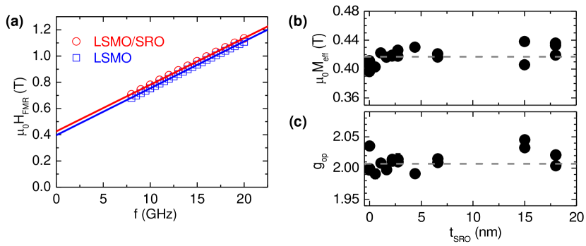
We first quantify the static magnetic properties of LSMO(/SRO) from the frequency dependence of . The Kittel equation for FMR in the out-of-plane configuration takes a simple linear form,
| (1) |
where is the permeability of free space, is the Bohr magneton, and is the Planck constant. As shown in Fig. 3(a), we only fit data points where is at least 0.2 T above to ensure that the film is saturated out-of-plane. Figures 3(b) and (c) plot the extracted and , respectively, each exhibiting no significant dependence on SRO thickness to within experimental uncertainty. The SRO overlayer therefore evidently does not modify the bulk magnetic properties of LSMO, and significant interdiffusion across the SRO/LSMO interface can be ruled out. The averaged of kA/m ( = T) is close to obtained from static magnetometery and implies negligible out-of-plane magnetic anisotropy; we thus assume in all subsequent analyses. The SRO-thickness independence of , averaging to , implies that the SRO overlayer does not generate a significant orbital contribution to magnetism in LSMO. Moreover, the absence of detectable change in with increasing may indicate that the imaginary component of the spin-mixing conductance Tserkovnyak2002a ; Tserkovnyak2002 is negligible at the LSMO/SRO interface.
The Gilbert damping parameter is extracted from the frequency dependence of (e.g., Figure 4(a)) by fitting the data with the standard linear relation,
| (2) |
The zero-frequency linewidth is typically attributed to sample inhomogeneity. We observe sample-to-sample variation of in the range mT with no systematic correlation with or the slope in Eq. 2. Moreover, similar to the analysis of , we only fit data obtained at 0.2 T above to minimize spurious broadening of at low fields. The linear slope of plotted against frequency up to 20 GHz is therefore a reliable measure of decoupled from in Eq. 2.
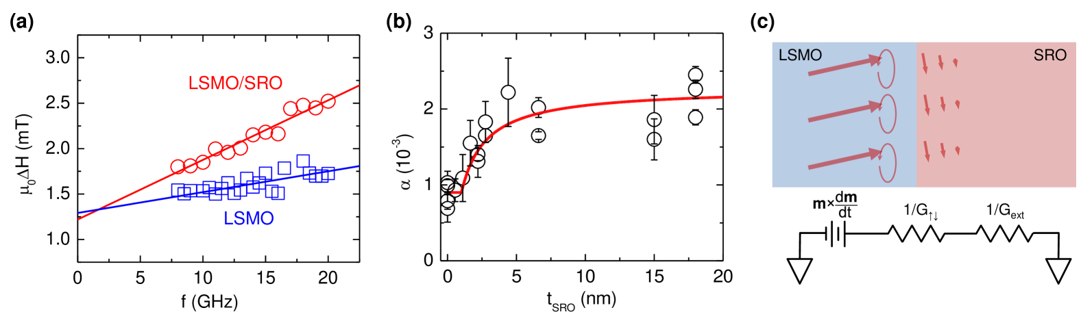
Figure 4(a) shows an LSMO single-layer film and an LSMO/SRO bilayer with similar . The slope, which is proportional to , is approximately a factor of 2 greater for LSMO/SRO. Figure 4(b) summarizes the dependence of on SRO-thickness, . For LSMO single-layer films we find , which is on the same order as previous reports of LSMO thin films Luo2013 ; Luo2015 ; Lee2016 ; Wahler2016 . This low damping is also comparable to the values reported in Heusler alloy thin films Mizukami2009 ; Durrenfeld2015a and may arise from the half-metal-like band structure of LSMO (Ref. (47)). LSMO can thus be an efficient source of spin current generated resonantly by microwave excitation.
With a few-nanometer thick overlayer of SRO, increases to 210-3 (Fig. 4(b)). This enhanced damping with the addition of SRO overlayer may arise from (1) spin scattering Nguyen2014 ; Rojas-Sanchez2014 at the LSMO/SRO interface or (2) spin pumping Tserkovnyak2002 ; Tserkovnyak2002a where nonequilibrium spins from LSMO are absorbed in the bulk of the SRO layer. Here, we assume that interfacial spin scattering is negligible, since 1 nm of SRO overlayer does not enhance significantly (Fig. 4(b)). This is in contrast with the pronounced interfacial effect in ferromagnet/Pt bilayers Nguyen2014 ; Rojas-Sanchez2014 , in which even 1 nm of Pt can increase by as much as a factor of 2 (Refs. (50; 51; 52)). In the following analysis and discussion, we show that spin pumping alone is sufficient for explaining the enhanced damping in LSMO with an SRO overlayer.
We now analyze the data in Fig. 4(b) using a one-dimensional model of spin pumping based on diffusive spin transport Boone2013 ; Boone2015 . The resonantly-excited magnetization precession in LSMO generates non-equilibrium spins polarized along , which is transverse to the magnetization unit vector . This non-equilibrium spin accumulation diffuses out to the adjacent SRO layer and depolarizes exponentially on the characteristic length scale . The spin current density at the LSMO/SRO interface can be written as Polianski2004 ; Boone2013
| (3) |
where is the reduced Planck constant, is the interfacial spin-mixing conductance per unit area, and is the spin conductance per unit area in the bulk of SRO. In Eq. 3, 1/ and 1/ constitute spin resistors in series such that the spin transport from LSMO to SRO can be regarded analogously as a “spin circuit,” as illustrated in Fig. 4(c). In literature, these interfacial and bulk spin conductances are sometimes lumped together as an “effective spin-mixing conductance” (Refs. (10; 11; 12; 13; 16; 44; 26; 23; 20)). We also note that the alternative form of the (effective) spin-mixing conductance , with units of m-2, is related to , with units of m-2, by k.
The functional form of is obtained by solving the spin diffusion equation with appropriate boundary conditions Polianski2004 ; Boone2013 ; Boone2015 . In the case of a ferromagnet/nonmagnetic-metal bilayer, we obtain
| (4) |
where is the resistivity of SRO, is the thickness of the SRO layer, and is the diffusion length of pumped spins in SRO. Finally, the outflow of spin current (Eq. 3) is equivalent to an enhancement of Gilbert damping Tserkovnyak2002 with respect to of LSMO with such that
| (5) |
Thus, two essential parameters governing spin transport and can be estimated by fitting the SRO-thickness dependence of (Fig. 4(b)) with Eq. 5.
In carrying out the fit, we fix . We note that increases by an order of magnitude compared to the bulk value of 210-6 m as is reduced to a few nm; also, at thicknesses of 3 monolayers (1.2 nm) or below, SRO is known to be insulating Xia2009 . We therefore use the -dependent shown in Appendix A while assuming is constant. An alternative fitting model that assumes a constant , which is a common approach in literature, is discussed in Appendix A.
The curve in Fig. 4(b) is generated by Eq. 5 with m-2 and nm. Given the scatter of the experimental data, acceptable fits are obtained with m-2 and nm. The estimated ranges of and also depend strongly on the assumptions behind the fitting model. For example, as shown in Appendix A, the constant- model yields m-2 and nm.
Nevertheless, we find that the estimated is on the same order of magnitude as those of various ferromagnet/transition-metal heterostructures Boone2015 ; Pai2015a ; Montoya2016a , signifying that the LSMO/SRO interface is reasonably transparent to spin current. More importantly, the short implies the presence of strong spin-orbit coupling that causes rapid spin scattering within SRO. This finding is consistent with a previous study on SRO at low temperature in the ferromagnetic state showing extremely fast spin relaxation with Gilbert damping (Ref. (28)). The short indicates that SRO may be suitable as a spin sink or detector in all-oxide spintronic devices.
IV In-plane FMR and Anisotropic Two-Magnon Scattering
In epitaxial thin films, the analysis of in-plane FMR is generally more complicated than that of out-of-plane FMR. High crystallinity of the film gives rise to a nonnegligible in-plane magnetocrystalline anisotropy field, which manifests in an in-plane angular dependence of and introduces another adjustable parameter in the nonlinear Kittel equation for in-plane FMR. Moreover, in in-plane FMR of epitaxial thin films often depends strongly on the magnetization orientation and exhibits nonlinear scaling with respect to frequency due to two-magnon scattering, a non-Gilbert mechanism for damping Lindner2003a ; Woltersdorf2004a ; Lenz2006 ; Zakeri2007a ; Barsukov2011 ; Kurebayashi2013 ; Lee2016 . We indeed find that damping of LSMO in the in-plane configuration is anisotropic and dominated by two-magnon scattering. We also observe evidence of enhanced two-magnon scattering with added SRO layers, which may be due to spin pumping from nonuniform magnetization precession.
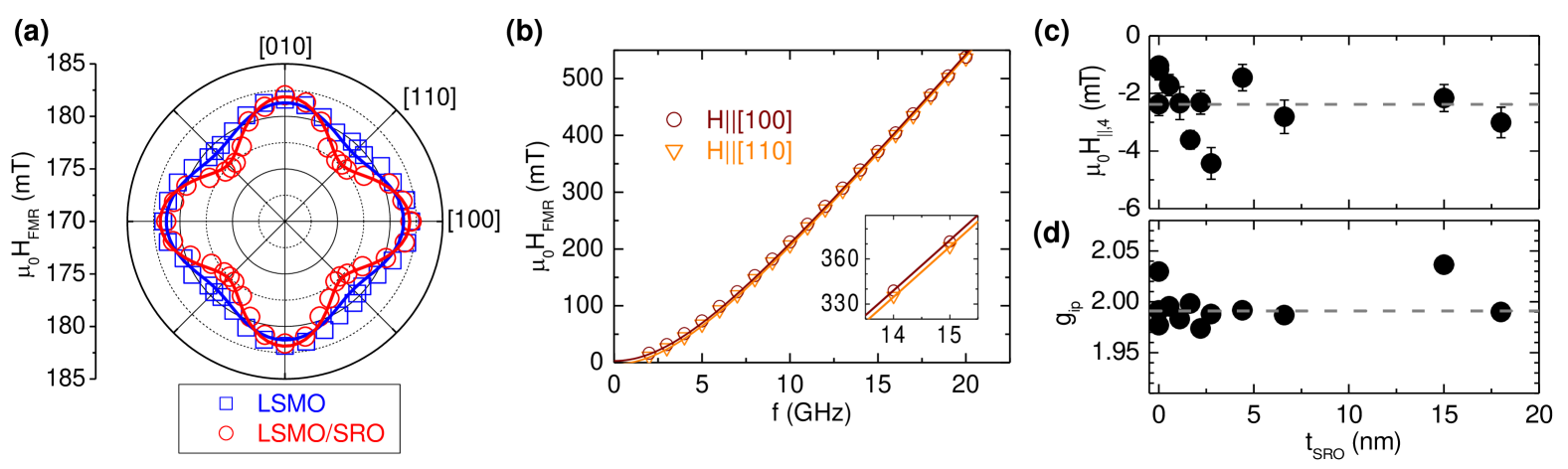
Figure 5(a) plots of a single-layer LSMO film and an LSMO/SRO bilayer as a function of applied field angle within the film plane. For both samples, we observe clear four-fold symmetry, which is as expected based on the epitaxial growth of LSMO on the cubic LSAT(001) substrate. Similar to previous FMR studies of LSMO on SrTiO3(001) Belmeguenai2010 ; Monsen2014 , the magnetic hard axes (corresponding to the axes of higher ) are along 100. The in-plane Kittel equation for thin films with in-plane cubic magnetic anisotropy is Farle1998 ,
| (6) |
where is the Landé g-factor that is obtained from in-plane FMR data, is the effective cubic anisotropy field, and is the in-plane field angle with respect to the [100] direction. Given that LSMO is magnetically very soft (coercivity on the order of 0.1 mT) at room temperature, we assume that the magnetization is parallel to the field direction, particularly with mT. In fitting the angular dependence (e.g., Fig. 5(a)) and frequency dependence (e.g., Fig. 5(b)) of to Eq. 6, we fix at the values obtained from out-of-plane FMR (Fig. 3(b)) so that and are the only fitting parameters. For the two samples shown in Fig. 5(a), the fits to the angular dependence and frequency dependence data yield consistent values of and . For the rest of the LSMO(/SRO) samples, we use the frequency dependence data with and to extract these parameters. Figures 5(c) and (d) show that and , respectively, exhibit no systematic dependence on , similar to the findings from out-of-plane FMR (Figs. 3(b),(c)). The in-plane cubic magnetocrystalline anisotropy in LSMO(/SRO) is relatively small, with averaging to 2.5 mT. averages out to , which is consistent with found from out-of-plane FMR.
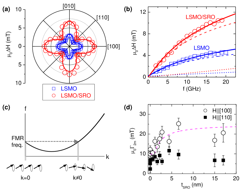
While the magnetocrytalline anisotropy in LSMO(/SRO) is found to be modest and independent of , we observe much more pronounced in-plane anisotropy and dependence in linewidth , as shown in Figs. 6(a) and (b). Figure 6(a) indicates that the in-plane dependence of is four-fold symmetric for both LSMO(10 nm) and LSMO(10 nm)/SRO(7 nm). is approximately a factor of 2 larger when the sample is magnetized along 100 compared to when it is magnetized along 110. One might attribute this pronounced anisotropy to anisotropic Gilbert damping Baker2016 , such that the sample magnetized along the hard axes 100 may lead to stronger damping. However, we find no general correlation between magnetocrystalline anisotropy and anisotropic : As we show in Appendix B, LSMO grown on NdGaO3(110) with pronounced uniaxial magnetocrystalline anisotropy exhibits identical when magnetized along the easy and hard axes. Moreover, whereas Gilbert damping should lead to a linear frequency dependence of , for LSMO(/SRO) the observed frequency dependence of is clearly nonlinear as evidenced in Fig. 6(b). The pronounced anisotropy and nonlinear frequency dependence of together suggest the presence of a different damping mechanism.
A well-known non-Gilbert damping mechanism in highly crystalline ultrathin magnetic films is two-magnon scattering Mills2002 ; Arias1999 ; McMichael1998 ; Lindner2003a ; Woltersdorf2004a ; Lenz2006 ; Zakeri2007a ; Barsukov2011 ; Kurebayashi2013 ; Lee2016 , in which uniformly precessing magnetic moments (a spin wave, or magnon mode, with wavevector ) dephase to a magnon mode with adjacent moments precessing with a finite phase difference. By considering both exchange coupling (which results in magnon energy proportional to ) and dipolar coupling (magnon energy proportional to ) among precessing magnetic moments, the and modes become degenerate in the magnon dispersion relation Mills2002 as illustrated in Fig. 6(c).
The transition from to is activated by defects that break the translational symmetry of the magnetic system by localized dipolar fields Mills2002 ; Arias1999 ; McMichael1998 . In LSMO(/SRO), the activating defects may be faceted such that two-magnon scattering is more pronounced when the magnetization is oriented along 100. One possibility is that LSMO thin films naturally form pits or islands faceted along 100 during growth. However, we are unable to consistently observe signs of such faceted defects in LSMO(/SRO) samples with an atomic force microscope (AFM). It is possible that these crystalline defects are smaller than the lateral resolution of our AFM setup (10 nm) or that these defects are not manifested in surface topography. Such defects may be point defects or nanoscale clusters of distinct phases that are known to exist intrinsically even in high-quality crystals of LSMO (Ref. (63)).
Although the definitive identification of defects that drive two-magnon scattering would require further investigation, we can rule out (1) atomic step terraces and (2) misfit dislocations as sources of anisotropic two-magnon scattering. (1) AFM shows that the orientation and density of atomic step terraces differ randomly from sample to sample, whereas the anisotropy in is consistently cubic with larger for 100 than 110. This is in agreement with the recent study by Lee et al., which shows anisotropic two-magnon scattering in LSMO to be independent of regularly-spaced parallel step terraces on a buffered-oxide etched SrTiO3 substrate Lee2016 . (2) Although Woltersdorf and Heinrich have found that misfit dislocations in Fe/Pd grown on GaAs are responsible for two-magnon scattering Woltersdorf2004a , such dislocations are expected to be virtually nonexistent in fully strained LSMO(/SRO) films on the closely-latticed matched LSAT substrates Takamura2008 ; Grutter2010 .
We assume that the in-plane four-fold anisotropy and nonlinear frequency dependence of are entirely due to two-magnon scattering. For a sample magnetized along a given in-plane crystallographic axis hk0 = 100 or 110, the two-magnon scattering contribution to is given by Arias1999
| (7) |
where and is the two-magnon scattering parameter. The angular dependence of is fitted with Woltersdorf2004a
| (8) |
Similarly, the frequency dependence of with the sample magnetized along [100] or [110], i.e., or , is well described by Eqs. 7 and 8. In principle, it should be possible to fit the linewidth data with , , and as adjustable parameters. In practice, the fit carried out this way is overspecified such that wide ranges of these parameters appear to fit the data. We therefore impose a constraint on by assuming that Gilbert damping for LSMO(/SRO) is isotropic: For each SRO thickness , is fixed to the value estimated from the fit curve in Fig. 4(c) showing out-of-plane FMR data. (This assumption is likely justified, since the damping for LSMO(10 nm) on NdGdO3(110) with strong uniaxial magnetic anisotropy is identical for the easy and hard directions, as shown in Appendix B.) To account for the uncertainty in the Gilbert damping in Fig. 4(c), we vary by 25% for fitting the frequency dependence of in-plane . Examples of fits using Eqs. 7 and 8 are shown in Fig. 6(a),(b).
Figure 6(d) shows that the SRO overlayer enhances the two-magnon scattering parameter by up to a factor of 2 for [100]. By contrast, for [110], although LSMO/SRO exhibits enhanced compared to LSMO, the enhancement in is obscured by the uncertainty in Gilbert damping. In Table I, we summarize the Gilbert and two-magnon contributions to for LSMO single layers and LSMO/SRO (averaged values for samples with nm) with [100] and [110]. Comparing the effective spin relaxation rates, and , reveals that two-magnon scattering dominates over Gilbert damping.
| LSMO | LSMO/SRO* | |
|---|---|---|
| Gilbert: | ||
| two-magnon: | ||
| two-magnon: |
-
•
* Averaged over samples with nm.
We now speculate on the mechanisms behind the enhancement in in LSMO/SRO, particularly for . One possibility is that SRO interfaced with LSMO directly increases the rate of two-magnon scattering, perhaps due to formation of additional defects at the surface of LSMO. If this were the case we might expect a significant increase and saturation of at small . However, in reality, increases for nm (Fig. 6(d)), which suggests spin scattering in the bulk of SRO. We thus speculate another mechanism, where magnons in LSMO are scattered by spin pumping into SRO. As shown by the guide-for-the-eye curve in Fig. 6(d), the dependence of (for [100]) may be qualitatively similar to the dependence of measured from out-of-plane FMR (Fig. 4(c)); this correspondence would imply that the same spin pumping mechanism, which is conventionally modeled to act on the mode, is also operative in the degenerate magnon mode in epitaxial LSMO. Indeed, previous studies have electrically detected the presence of spin pumping from magnons by the inverse spin-Hall effect in Y3Fe5O12/Pt bilayers Sandweg2011 ; DaSilva2013 ; Manuilov2015 . However, we cannot conclusively attribute the observed FMR linewidth broadening in LSMO/SRO to such spin pumping, since it is unclear whether faster relaxation of magnons should necessarily cause faster relaxation of the FMR mode. Regardless of its origin, the pronounced anisotropic two-magnon scattering introduces additional complexity to the analysis of damping in LSMO/SRO and possibly in other similar ultrathin epitaxial magnetic heterostructures.
V Summary
We have demonstrated all-oxide perovskite bilayers of LSMO/SRO that form spin-source/spin-sink systems. From out-of-plane FMR, we deduce a low Gilbert damping parameter of 110-3 for LSMO. The two-fold enhancement in Gilbert damping with an SRO overlayer is adequately described by the standard model of spin pumping based on diffusive spin transport. We arrive at an estimated spin-mixing conductance m-2 and spin diffusion length nm, which indicate reasonable spin-current transparency at the LSMO/SRO interface and strong spin scattering within SRO. From in-plane FMR, we reveal pronounced non-Gilbert damping, attributed to two-magnon scattering, which results in a nonlinear frequency dependence and anisotropy in linewidth. The magnitude of two-magnon scattering increases with the addition of an SRO overlayer, pointing to the presence of spin pumping from nonuniform spin wave modes. Our findings lay the foundation for understanding spin transport and magnetization dynamics in epitaxial complex oxide heterostructures.
Acknowledgements
We thank Di Yi, Sam Crossley, Adrian Schwartz, Hankyu Lee, and Igor Barsukov for helpful discussions, and Tianxiang Nan and Nian Sun for the design of the coplanar waveguide. This work was funded by the National Security Science and Engineering Faculty Fellowship of the Department of Defense under Contract No. N00014-15-1-0045.
Appendix A: Spin Pumping and SRO Resistivity
When fitting the dependence of the Gilbert damping parameter on spin-sink thickness, a constant bulk resistivity for the spin sink layer is often assumed in literature. By setting the resistivity of SRO to the bulk value m and fitting the -versus- data (Fig. 4(c) and reproduced in Fig. 7(a)) to Eq. 5, we arrive at m-2 and nm. The fit curve is insensitive to larger values of because the bulk spin resistance 1/, with the relatively large resistivity of SRO, dominates over the interfacial spin resistance 1/ (see Eqs. 4 and 5). As shown by the dotted curve in Fig. 7, this simple constant- model appears to mostly capture the -dependence of . This model of course indicates finite spin pumping at even very small SRO thickness 1 nm, which is likely nonphysical since SRO should be insulating in this thickness regime Xia2009 . Indeed, estimated with this model should probably be considered a phenomenological parameter: As pointed out by recent studies, strictly speaking, a physically meaningful estimation of should take into account the thickness dependence of the resistivity of the spin sink layer Boone2015 ; Nguyen2016 ; Montoya2016a , especially for SRO whose thickness dependence of resistivity is quite pronounced.

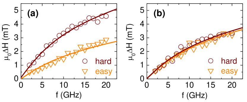
Figure 7(b) plots the SRO-thickness dependence of the resistivity of SRO films deposited on LSAT(001) measured in the four-point van der Pauw geometry. The trend can be described empirically by
| (9) |
where m is the resistivity of SRO in the bulk limit, m2 is the surface resistivity coefficient, and nm is the threshold thickness below which the SRO layer is essentially insulating. The value of agrees with literature reporting that SRO is insulating at thickness of 3 monolayers (1.2 nm) or below Xia2009 . Given the large deviation of from the bulk value, especially at small , the trend in Fig. 7(b) suggests that taking into account the dependence of is a sensible approach.
Appendix B: In-Plane Damping of LSMO on Different Substrates
In Fig. 8, we compare the frequency dependence of for 10-nm thick LSMO films deposited on different substrates: LSAT(001) and NdGaO3(110). (NdGaO3 is an orthorhombic crystal and has a -pseudocubic parameter of 3.86 Å, such that (001)-oriented LSMO grows on the (110)-oriented surface of NdGaO3.) As shown in Sec. IV, LSMO on LSAT(001) exhibits cubic magnetic anisotropy within the film plane with the and as the easy and hard axes, respectively. LSMO on NdGaO3(110) exhibits uniaxial magnetic anisotropy within the film plane with and [001] of NdGaO3 as the easy and hard axes, respectively. Boschker2009 Whereas LSMO on LSAT(001) shows distinct magnitudes of damping when the film is magnetized along the easy and hard axes (Figs. 8(a) and 6(a)), in LSMO on NdGaO3(110) damping is identical for both the easy and hard axes (Figs. 8(b)). These results demonstrate that higher damping (wider linewidth) is in general not linked to the magnetic hard axis of LSMO.
References
- (1) R. L. Stamps, S. Breitkreutz, J. Åkerman, A. V. Chumak, Y. Otani, G. E. W. Bauer, J.-U. Thiele, M. Bowen, S. A. Majetich, M. Kläui, I. L. Prejbeanu, B. Dieny, N. M. Dempsey, and B. Hillebrands, J. Phys. D. Appl. Phys. 47, 333001 (2014).
- (2) A. Hoffmann, IEEE Trans. Magn. 49, 5172 (2013).
- (3) J. Sinova, S. O. Valenzuela, J. Wunderlich, C. H. Back, and T. Jungwirth, Rev. Mod. Phys. 87, 1213 (2015).
- (4) A. Hoffmann and S. D. Bader, Phys. Rev. Appl. 4, 047001 (2015).
- (5) A. Brataas, A. D. Kent, and H. Ohno, Nat. Mater. 11, 372 (2012).
- (6) N. Locatelli, V. Cros, and J. Grollier, Nat. Mater. 13, 11 (2014).
- (7) A. V. Chumak, V. I. Vasyuchka, A. A. Serga, and B. Hillebrands, Nat. Phys. 11, 453 (2015).
- (8) Y. Tserkovnyak, A. Brataas, and G. Bauer, Phys. Rev. Lett. 88, 117601 (2002).
- (9) Y. Tserkovnyak, A. Brataas, and G. Bauer, Phys. Rev. B 66, 224403 (2002).
- (10) F. D. Czeschka, L. Dreher, M. S. Brandt, M. Weiler, M. Althammer, I.-M. Imort, G. Reiss, A. Thomas, W. Schoch, W. Limmer, H. Huebl, R. Gross, and S. T. B. Goennenwein, Phys. Rev. Lett. 107, 046601 (2011).
- (11) Y. Sun, H. Chang, M. Kabatek, Y.-Y. Song, Z. Wang, M. Jantz, W. Schneider, M. Wu, E. Montoya, B. Kardasz, B. Heinrich, S. G. E. te Velthuis, H. Schultheiss, and A. Hoffmann, Phys. Rev. Lett. 111, 106601 (2013).
- (12) W. Zhang, M. B. Jungfleisch, W. Jiang, J. Sklenar, F. Y. Fradin, J. E. Pearson, J. B. Ketterson, and A. Hoffmann, J. Appl. Phys. 117, 172610 (2015).
- (13) C. Du, H. Wang, P. C. Hammel, and F. Yang, J. Appl. Phys. 117, 172603 (2015).
- (14) K. Ando, S. Takahashi, J. Ieda, H. Kurebayashi, T. Trypiniotis, C. H. W. Barnes, S. Maekawa, and E. Saitoh, Nat. Mater. 10, 655 (2011).
- (15) K. Ando, S. Watanabe, S. Mooser, E. Saitoh, and H. Sirringhaus, Nat. Mater. 12, 622 (2013).
- (16) M. Jamali, J. S. Lee, J. S. Jeong, F. Mahfouzi, Y. Lv, Z. Zhao, B. K. Nikolić, K. A. Mkhoyan, N. Samarth, and J.-P. Wang, Nano Lett. 15, 7126 (2015).
- (17) P. Zubko, S. Gariglio, M. Gabay, P. Ghosez, and J.-M. Triscone, Annu. Rev. Condens. Matter Phys. 2, 141 (2011).
- (18) H. Y. Hwang, Y. Iwasa, M. Kawasaki, B. Keimer, N. Nagaosa, and Y. Tokura, Nat. Mater. 11, 103 (2012).
- (19) S. Majumdar and S. van Dijken, J. Phys. D. Appl. Phys. 47, 034010 (2014).
- (20) E. Lesne, Y. Fu, S. Oyarzun, J. C. Rojas-Sánchez, D. C. Vaz, H. Naganuma, G. Sicoli, J.-P. Attané, M. Jamet, E. Jacquet, J.-M. George, A. Barthélémy, H. Jaffrès, A. Fert, M. Bibes, and L. Vila, Nat. Mater. (2016).
- (21) G. Y. Luo, C. R. Chang, and J. G. Lin, IEEE Trans. Magn. 49, 4371 (2013).
- (22) G. Y. Luo, M. Belmeguenai, Y. Roussigné, C. R. Chang, J. G. Lin, and S. M. Chérif, AIP Adv. 5, 097148 (2015).
- (23) H. K. Lee, I. Barsukov, A. G. Swartz, B. Kim, L. Yang, H. Y. Hwang, and I. N. Krivorotov, AIP Adv. 6, 055212 (2016).
- (24) S. M. Haidar, Y. Shiomi, J. Lustikova, and E. Saitoh, Appl. Phys. Lett. 107, 152408 (2015).
- (25) V. A. Atsarkin, B. V. Sorokin, I. V. Borisenko, V. V. Demidov, and G. A. Ovsyannikov, J. Phys. D. Appl. Phys. 49, 125003 (2016).
- (26) M. Wahler, N. Homonnay, T. Richter, A. Müller, C. Eisenschmidt, B. Fuhrmann, and G. Schmidt, Sci. Rep. 6, 28727 (2016).
- (27) G. Koster, L. Klein, W. Siemons, G. Rijnders, J. S. Dodge, C.-B. Eom, D. H. A. Blank, and M. R. Beasley, Rev. Mod. Phys. 84, 253 (2012).
- (28) M. C. Langner, C. L. S. Kantner, Y. H. Chu, L. M. Martin, P. Yu, J. Seidel, R. Ramesh, and J. Orenstein, Phys. Rev. Lett. 102, 177601 (2009).
- (29) A. Azevedo, L. H. Vilela-Leão, R. L. Rodríguez-Suárez, A. F. Lacerda Santos, and S. M. Rezende, Phys. Rev. B 83, 144402 (2011).
- (30) L. Bai, P. Hyde, Y. S. Gui, C.-M. Hu, V. Vlaminck, J. E. Pearson, S. D. Bader, and A. Hoffmann, Phys. Rev. Lett. 111, 217602 (2013).
- (31) M. Obstbaum, M. Härtinger, H. G. Bauer, T. Meier, F. Swientek, C. H. Back, and G. Woltersdorf, Phys. Rev. B 89, 060407 (2014).
- (32) J. Lindner, K. Lenz, E. Kosubek, K. Baberschke, D. Spoddig, R. Meckenstock, J. Pelzl, Z. Frait, and D. L. Mills, Phys. Rev. B 68, 060102 (2003).
- (33) G. Woltersdorf and B. Heinrich, Phys. Rev. B 69, 184417 (2004).
- (34) K. Lenz, H. Wende, W. Kuch, K. Baberschke, K. Nagy, and A. Jánossy, Phys. Rev. B 73, 144424 (2006).
- (35) K. Zakeri, J. Lindner, I. Barsukov, R. Meckenstock, M. Farle, U. von Hörsten, H. Wende, W. Keune, J. Rocker, S. S. Kalarickal, K. Lenz, W. Kuch, K. Baberschke, and Z. Frait, Phys. Rev. B 76, 104416 (2007).
- (36) I. Barsukov, F. M. Römer, R. Meckenstock, K. Lenz, J. Lindner, S. Hemken to Krax, A. Banholzer, M. Körner, J. Grebing, J. Fassbender, and M. Farle, Phys. Rev. B 84, 140410 (2011).
- (37) H. Kurebayashi, T. D. Skinner, K. Khazen, K. OlejniÌk, D. Fang, C. Ciccarelli, R. P. Campion, B. L. Gallagher, L. Fleet, A. Hirohata, and A. J. Ferguson, Appl. Phys. Lett. 102, 062415 (2013).
- (38) C. T. Boone, H. T. Nembach, J. M. Shaw, and T. J. Silva, J. Appl. Phys. 113, 153906 (2013).
- (39) C. T. Boone, J. M. Shaw, H. T. Nembach, and T. J. Silva, J. Appl. Phys. 117, 223910 (2015).
- (40) R. Arias and D. L. Mills, Phys. Rev. B 60, 7395 (1999).
- (41) Y. Takamura, R. V. Chopdekar, E. Arenholz, and Y. Suzuki, Appl. Phys. Lett. 92, 162504 (2008).
- (42) A. Grutter, F. Wong, E. Arenholz, M. Liberati, and Y. Suzuki, J. Appl. Phys. 107, 09E138 (2010).
- (43) M. Golosovsky, P. Monod, P. K. Muduli, and R. C. Budhani, Phys. Rev. B 76, 184413 (2007).
- (44) M. Haertinger, C. H. Back, J. Lotze, M. Weiler, S. Geprägs, H. Huebl, S. T. B. Goennenwein, and G. Woltersdorf, Phys. Rev. B 92, 054437 (2015).
- (45) S. Mizukami, D. Watanabe, M. Oogane, Y. Ando, Y. Miura, M. Shirai, and T. Miyazaki, J. Appl. Phys. 105, 07D306 (2009).
- (46) P. Dürrenfeld, F. Gerhard, J. Chico, R. K. Dumas, M. Ranjbar, A. Bergman, L. Bergqvist, A. Delin, C. Gould, L. W. Molenkamp, and J. Åkerman, Phys. Rev. B 92, 214424 (2015).
- (47) C. Liu, C. K. A. Mewes, M. Chshiev, T. Mewes, and W. H. Butler, Appl. Phys. Lett. 95, 022509 (2009).
- (48) H. Nguyen, W. Pratt, and J. Bass, J. Magn. Magn. Mater. 361, 30 (2014).
- (49) J.-C. Rojas-Sánchez, N. Reyren, P. Laczkowski, W. Savero, J.-P. Attané, C. Deranlot, M. Jamet, J.-M. George, L. Vila, and H. Jaffrès, Phys. Rev. Lett. 112, 106602 (2014).
- (50) S. Azzawi, A. Ganguly, M. Tokaç, R. M. Rowan-Robinson, J. Sinha, A. T. Hindmarch, A. Barman, and D. Atkinson, Phys. Rev. B 93, 054402 (2016).
- (51) M. Caminale, Phys. Rev. B 94, 014414 (2016).
- (52) S. Emori, T. Nan, A. M. Belkessam, X. Wang, A. D. Matyushov, C. J. Babroski, Y. Gao, H. Lin, and N. X. Sun, Phys. Rev. B 93, 180402 (2016).
- (53) M. Polianski and P. Brouwer, Phys. Rev. Lett. 92, 026602 (2004).
- (54) J. Xia, W. Siemons, G. Koster, M. R. Beasley, and A. Kapitulnik, Phys. Rev. B 79, 140407 (2009).
- (55) C.-F. Pai, Y. Ou, L. H. Vilela-Leão, D. C. Ralph, and R. A. Buhrman, Phys. Rev. B 92, 064426 (2015).
- (56) E. Montoya, P. Omelchenko, C. Coutts, N. R. Lee-Hone, R. Hübner, D. Broun, B. Heinrich, and E. Girt, Phys. Rev. B 94, 054416 (2016).
- (57) M. Belmeguenai, S. Mercone, C. Adamo, L. Méchin, C. Fur, P. Monod, P. Moch, and D. G. Schlom, Phys. Rev. B 81, 054410 (2010).
- (58) Å. Monsen, J. E. Boschker, F. Macià, J. W. Wells, P. Nordblad, A. D. Kent, R. Mathieu, T. Tybell, and E. Wahlström, J. Magn. Magn. Mater. 369, 197 (2014).
- (59) M. Farle, Reports Prog. Phys. 61, 755 (1998).
- (60) A. A. Baker, A. I. Figueroa, C. J. Love, S. A. Cavill, T. Hesjedal, and G. van der Laan, Phys. Rev. Lett. 116, 047201 (2016).
- (61) D. Mills and S. M. Rezende, Spin Damping in Ultrathin Magnetic Films, in Spin Dyn. Confin. Magn. Struct. II, edited by B. Hillebrands and K. Ounadjela, chap. 2, pp. 27–58, Springer, 2002.
- (62) R. D. McMichael, M. D. Stiles, P. J. Chen, and W. F. Egelhoff, J. Appl. Phys. 83, 7037 (1998).
- (63) E. Dagotto, J. Burgy, and A. Moreo, Solid State Commun. 126, 9 (2003).
- (64) C. W. Sandweg, Y. Kajiwara, A. V. Chumak, A. A. Serga, V. I. Vasyuchka, M. B. Jungfleisch, E. Saitoh, and B. Hillebrands, Phys. Rev. Lett. 106, 216601 (2011).
- (65) G. L. da Silva, L. H. Vilela-LeaÌfo, S. M. Rezende, and A. Azevedo, Appl. Phys. Lett. 102, 012401 (2013).
- (66) S. A. Manuilov, C. H. Du, R. Adur, H. L. Wang, V. P. Bhallamudi, F. Y. Yang, and P. C. Hammel, Appl. Phys. Lett. 107, 042405 (2015).
- (67) M.-H. Nguyen, D. C. Ralph, and R. A. Buhrman, Phys. Rev. Lett. 116, 126601 (2016).
- (68) H. Boschker, M. Mathews, E. P. Houwman, H. Nishikawa, A. Vailionis, G. Koster, G. Rijnders, and D. H. A. Blank, Phys. Rev. B 79, 214425 (2009).