Quantum random number generation using an on-chip plasmonic beamsplitter
Abstract
We report an experimental realisation of a quantum random number generator using a plasmonic beamsplitter. Free-space single photons are converted into propagating single surface plasmon polaritons on a gold stripe waveguide via a grating. The surface plasmons are then guided to a region where they are scattered into one of two possible outputs. The presence of a plasmonic excitation in a given output determines the value of a random bit generated from the quantum scattering process. Using a stream of single surface plasmons injected into the beamsplitter we achieve a quantum random number generation rate of 2.37 Mbits/s even in the presence of loss. We characterise the quality of the random number sequence generated, finding it to be comparable to sequences from other quantum photonic-based devices. The compact nature of our nanophotonic device makes it suitable for tight integration in on-chip applications, such as in quantum computing and communication schemes.
Introduction.— Plasmonic systems exhibiting quantum effects are currently being explored for their potential in emerging quantum technologies Tame13 . Compared to standard dielectric systems traditionally used in photonics, plasmonic systems provide a means to confine light to much smaller scales, far below the diffraction limit Takahara97 ; Takahara09 . In the classical regime, this has opened up a range of applications, including nano-imaging Kawata09 , nano-sensing Homola99 ; Anker08 , hybrid electro-optic circuitry Ozbay06 and new kinds of photonic materials Soukoulis11 ; Meinzer14 . The high confinement of light is achieved by the interaction of the electromagnetic field with free electrons on the surface of a metal to form a joint state of light and matter – a surface plasmon polariton (SPP). In the quantum regime, studies have shown the enhancement of the interaction between single SPPs and emitters, such as quantum dots Buckley12 and nitrogen vacancy centres Aharonovich11 . This enhancement has been used to demonstrate compact single-photon sources Akimov07 ; Kolesov09 ; Huck11 ; Cuche11 and design new schemes for single-photon switches Chang07 ; Kolchin11 ; Chang14 , both of which are important devices for quantum technology OBrien05 . Other studies have shown that SPPs maintain well the quantum features of the photons used to excite them, including quantum correlations DiMartino12 , quantum interference Heeres13 ; Fakonas14 ; DiMartino14 ; Cai14 ; Fujii14 and entanglement Alte02 .
Despite many promising results for plasmonic systems in the quantum regime, they are well known to be inherently lossy Maier07 and as such their application to quantum information processing has not been well developed. Initial studies have shown that entanglement can be generated by using plasmonic waveguides even in the presence of loss, either by using loss as a resource Gonz11 , or circumventing it with appropriate methods Lee13 . By using particular types of encoded quantum states it has also been shown that one can propagate quantum information over arbitrary distances on lossy plasmonic waveguides Hanson15 . Most recently, it has been shown that the sensitivity in plasmonic sensing can be enhanced beyond the classical regime by using quantum resources, even in the presence of loss Fan15 ; Pooser15 ; Lee16 . It is clear from these studies that despite their significant loss, plasmonic systems are still able to exploit quantum effects and carry out useful quantum tasks. The added benefit is that they can do these tasks at a much smaller scale and footprint than conventional photonics, which makes plasmonics an attractive platform for compact nanophotonic quantum information processing.
In this work we further strengthen the use of plasmonics for quantum information processing. We experimentally demonstrate a quantum random number generator using a plasmonic beamsplitter. Quantum random number generators exploit the inherent randomness that is central to quantum mechanics, which makes them ideal sources of entropy. Using classical methods, true random number generation is hard to accomplish, as the unpredictability of the generation relies on an incomplete knowledge of a given system. On the other hand, in a quantum system true randomness is an essential part of the underlying quantum mechanics. True random numbers are important in many applications in science and technology, including in cryptography, simulation of economic, traffic and agricultural models, and for coordination in computer networks Her16 . A device that generates true random numbers using quantum mechanics is therefore an important technological component.
Previously, single photons have been used as quantum generators of random numbers in bulk setups in various forms, including a branching path generator Rarity94 ; Stefanov00 ; Jenn00 , time of arrival generator Ma05 ; Stip07 ; Yu10 , photon counting generator Furst10 ; Ren11 ; Lopes14 and many others Her16 . Most recently on-chip quantum random number generators have been realised using one or more of the above methods Sang14 ; Khan15 ; Tisa15 ; Abellan16 . In our experiment, we use the branching path method to generate random numbers quantum mechanically. We excite single SPPs on a gold stripe waveguide and scatter them into one of two possible outputs of a plasmonic beamsplitter. This enables a true random bit to be generated from the quantum scattering process. We then characterise the quality of the random number sequence generated, finding it to be comparable to other methods of photonic-based quantum random number generation Her16 . The benefits of a plasmonic splitting device is that it is highly compact and therefore suitable for tight integration in an on-chip setting, where it could be used as a module in a quantum computing or quantum communication task.
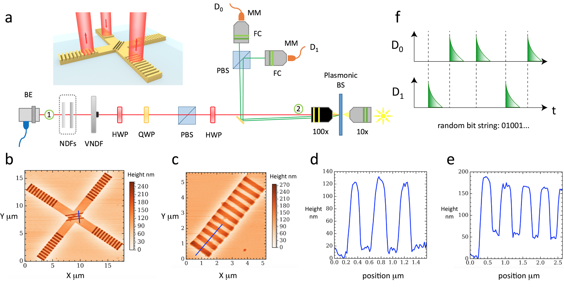
Experimental setup.— The setup used to investigate quantum random number generation using the plasmonic beamsplitter is shown in Fig. 1a, where a compound microscope is used to excite single SPPs on a plasmonic beamsplitter made from gold, illustrated in the inset of Fig. 1a. Each arm of the beamsplitter is 2 m in width and 70 nm in height. At the ends of the arms and the intersection there is a surface-relief grating of height 90 nm. The end gratings with 11 steps of period 700 nm serve as inputs and outputs for converting photons to SPPs and back again, while the centre grating with 3 steps of period of 500 nm acts as a partial mirror, providing a splitting DiMartino14 . A single SPP excited at one input grating propagates along the waveguide and upon reaching the central grating there is a probability that it is transmitted into the forward output and a probability that it is reflected into the perpendicular output.
This type of scattering process has been studied in much detail in the classical regime Lamprecht2001 ; Ditlbacher2002 ; Weeber2005 ; Gonzalez2006 and more recently in the quantum regime DiMartino14 . While the aim of the central grating is to act as a partial mirror, transmitting and reflecting part of the incoming excitation, there is also some scattering into the far-field and absorption in the metal. The reflection, transmission and loss coefficients in the classical regime are translated into probability amplitudes in the quantum regime via energy conservation arguments Barnett98 . Such a lossy quantum splitting has been studied extensively for photons Barnett98 and surface plasmons Ballester10 theoretically, and experimentally observed in recent studies of the plasmonic Hong-Ou-Mandel effect Heeres13 ; Fakonas14 ; DiMartino14 ; Cai14 ; Fujii14 . These results allow us to faithfully model the scattering process as a lossy quantum optical beamsplitter. As such, the branching path model for our source of randomness (entropy) is valid Her16 ; Stip15 ; Stip15a . The impact of loss on the scattering process and subsequent random number generation will be discussed later.
During propagation, the SPPs are highly confined to the surface of the waveguide, with a perpendicular characteristic length much less than the free-space wavelength DiMartino12 ; DiMartino14 . This confinement, together with the in-plane footprint of m m makes the plasmonic beamsplitter a highly compact device, comparable in size to current state-of-the-art on-chip quantum photonic waveguide couplers Bonneau12 ; Zhang12 ; Wang15 ; Abellan16 . Shorter in/out gratings, lead-in propagation distance to the splitting region and waveguide widths are possible in principle Lamprecht2001 ; Ditlbacher2002 ; Zia2005 ; Weeber2005 ; Gonzalez2006 ; Zenin16 , and would enable further reduction in size if needed for a given application. In addition, while the beamsplitter in our experiment is excited by an external source and the detection is performed off-chip, as in many recent quantum photonic demonstrations Bonneau12 ; Zhang12 ; Carolan15 , future work on the integration of sources Akimov07 ; Kolesov09 ; Huck11 ; Cuche11 ; Clemmen09 and detectors Heeres13 ; Falk09 would enable a completely standalone device.
The beamsplitter is fabricated on a silica glass substrate of thickness 0.17 mm (refractive index ) by a combination of electron beam lithography (EBL) and electron beam evaporation (EBE). For the waveguide sections (layer 1, thickness 70 nm), a positive resist is spin coated on the substrate, with EBL used to define the waveguide regions. A lift-off technique is then used, with an adhesion layer of Ti (thickness 2-3 nm) deposited first and then the Au layer using EBE. The gratings (layer 2, thickness 90 nm) are formed similarly to the waveguides using alignment marks to match up layer 1 and 2. A three-dimensional image of the final beamsplitter structure is then obtained using an atomic force microscope (NT-MDT Smena), as shown in Figs. 1b-e.
To excite single SPPs in the beamsplitter a coherent light source in the form of a nm continuous-wave laser operating above the lasing threshold at 35 mA is used (Thorlabs LPS-785-FC). The light is injected into the microscope stage via a beam expander (BE). The collimated beam runs through a combination of two fixed and one variable neutral density (ND) filters, which are used to attenuate the coherent light down to the single-photon regime. The prepared source of light can be described by a weak coherent state , with photon number distribution and as the mean excitation number. In this regime, the two dominant components are and . Using single-photon avalanche diode (SPAD) detectors (Excelitas SPCM-AQRH-15) for each output of the beamsplitter, the vacuum component is removed by postselection, i.e. when either detector clicks the quantum state injected into the input grating of the beamsplitter was a single photon Jenn00 .
To clean up the polarisation of the input state, a polarising beam splitter (PBS) is used to select horizontally polarised photons, while a preceding quarter-wave plate (QWP) and half-wave plate (HWP) are used to control the incident polarisation. The beam is focused onto one input grating of the plasmonic beamsplitter (diffraction-limited spot) using a 100x microscope objective and its polarisation is adjusted using an additional HWP to maximise the in-coupling efficiency for conversion of photons to SPPs DiMartino12 . The two output modes of the beamsplitter are collected by the same objective, and are then picked off by a knife-edge mirror and directed onto a PBS. This PBS separates the two orthogonally polarised outputs which are then coupled into multimode fibres that lead to separate SPAD detectors. The detectors are each connected to a channel of a Picoquant TimeHarp 260, which in turn is connected to a PC for data acquisition. In time-tagging mode the TimeHarp records the detector at which a photon arrives and its arrival time to a resolution of ps.
In order to excite single SPPs we require that the average photon number is much less than one per coherence time of the source Jenn00 . The coherence time is given by , where is the frequency bandwidth of the laser Saleh07 . Using THz we have s. Thus the rate of photons injected into the plasmonic beamsplitter, , must be much less than s-1. Due to the low initial intensity required, the input rate in our setup was calculated by measuring the power at position 1 in Fig. 1a and then measuring the transmission efficiency of all the optics between position 1 and 2. This yielded a transmission factor of . With the power at position 1 as mW we obtain an input power of W into the microscope objective. Dividing this by the average photon energy gives s-1. While this is clearly much less than , an additional constraint comes from the SPAD detector dead time ns Her16 ; Stip15 . If a detector detects a photon it will not detect another within this time. Thus for 2 photons arriving within only one will be detected. This leads to an excess of substrings 01 and 10, as the detectors miss the substrings 00 and 11 at random places Stip15 . The input power is therefore set using a variable ND filter so that the detected rate in each detector is s-1 s-1.
Losses occur in the setup due to scattering (during interconversion of photons to SPPs at the gratings and the SPP splitting) and absorption (during SPP propagation). These have the same effect on the quantum properties of the excitations and can be combined Tame08 ; Ballester10 ; DiMartino12 . At the input stage, which includes the grating interconversion efficiency ( at nm) and propagation to the splitting region ( using waveguide length m and decay length m), the losses reduce the overall amplitude of the coherent state before it arrives at the splitting region. This reduces the component relative to , which therefore reduces the total number of post-selected single SPPs that are input to the splitter. The reduction can be compensated by simply increasing the initial amplitude of the coherent state. At the output stage, which includes the splitting, propagation from the splitting region and grating interconversion (with symmetrical loss in the two outputs), losses remove an equal number of single excitations in the two arms. This leads to a balanced reduction in the number of 0’s and 1’s measured. The reduction can again be compensated by increasing the initial amplitude of the coherent state.
In general, when compensating for loss by increasing the initial amplitude of the coherent state it is important to ensure that two factors are taken into consideration. The first is that the beamsplitter must operate in the single-excitation regime and so the average excitation number arriving at the splitting region should be much less than one per coherence time of the coherent state. This limits the amount by which the initial amplitude can be increased. The second factor is that any bias in the random numbers generated should be minimized and so the detected rate from the outputs must be less than the reciprocal of the detector dead time. This also limits the amount by which the initial amplitude can be increased. Both factors depend on the geometry of the beamsplitter (gratings, arm length and splitting efficiency) and the type of detector used. By setting the input power in our experiment to the value specified, we have fixed the initial amplitude of the input state in order to satisfy both factors, as detailed above.
At the measurement stage the detection of photons from the plasmonic beamsplitter outputs produce signals in the form of pulses from the SPADs, as illustrated in Fig. 1f. These signals are sent to the TimeHarp which records the arrival times of the pulses from both channels and from this we extract a random binary sequence. The sequence is constructed by denoting a pulse from detector 0 as the binary digit 0 and a pulse from detector 1 as the binary digit 1. A total of 82,604,923 binary digits (bits) were acquired over a 34 s period, corresponding to a rate of Mbits/s.
Characterisation of random number sequence.— We characterise our random bit sequence by applying a number of standardised tests Jenn00 ; Her16 . These tests are employed to determine if the generated sequence exhibits characteristics typical of a true random bit sequence. In what follows we describe the tests performed on a sample of Mbits and present the results:
(i) Autocorrelation: We first calculate the correlation coefficients Edwards76 of the bit sequence with itself up to a 31-bit delay in order to examine any short-ranged correlations and periodicity. The coefficients lie in the interval [-1, 1]. A value of 1 and -1 indicate correlation and anti-correlation respectively, while a value of 0 suggests uncorrelated bits. Fig. 2a is a plot of the obtained coefficients, and shows only a small negative correlation between adjacent bits, after which the correlation remains consistently close to zero. The inset shows a zoomed region that omits the first data point in order to emphasise the lower lying points. The negative correlation can be seen, as well as a small positive correlation for delays greater than one bit. The main sources of these residual correlations in a beamsplitter scenario can be attributed to a combination of detector dark counts, deadtime and afterpulsing in the SPADs Stip15 ; Stip15a .
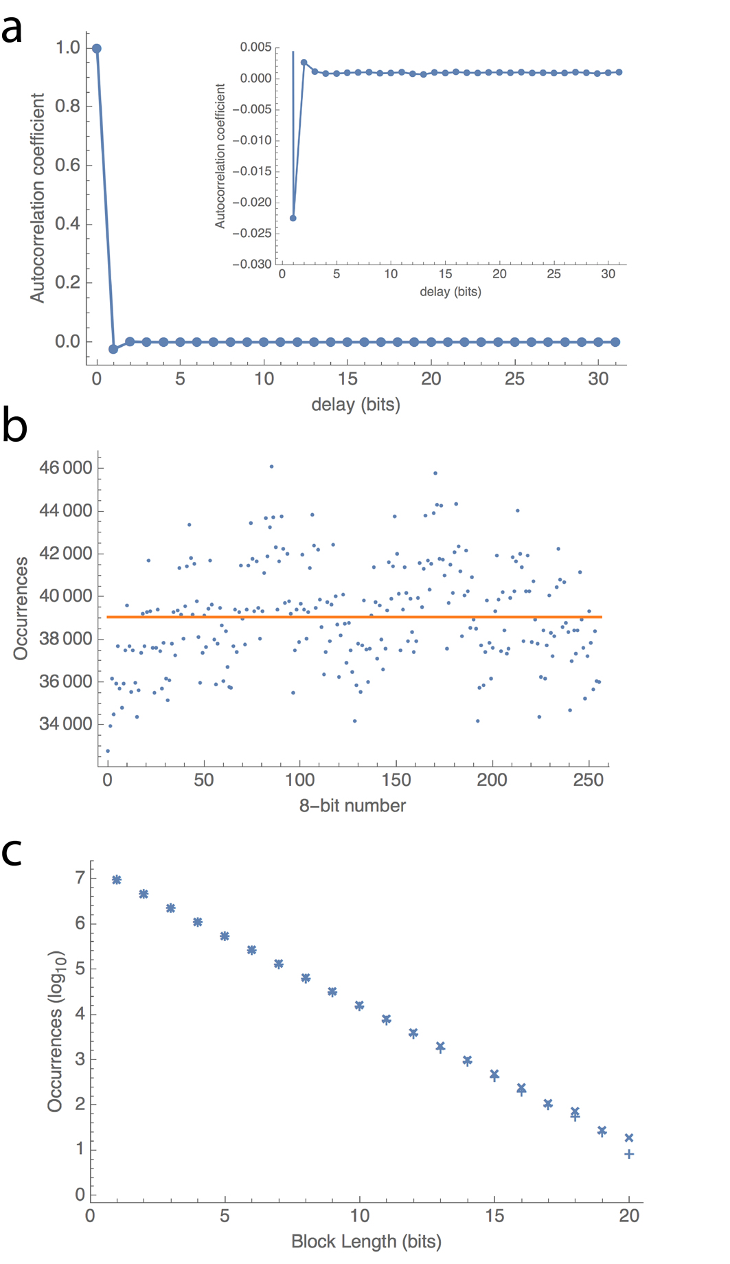
(ii) Uniform distribution of -bit blocks: For a true random bit sequence, all possible -bit combinations should be equally probable. We consider single bits and 8-bit blocks. In the case of single bits we should have an equal number of zeros and ones for a large enough sample. For 8-bit blocks that are converted to unsigned integers, we expect a uniform distribution of occurrences over the domain . Furthermore, the average must approach the value of 127.5. Using our 80 Mbit sample we find the proportion of ones as 0.5023 and zeros as 0.4977, showing a small bias towards one. The distribution of 8-bit integers is shown in Fig. 2b. The average of the integers is 128.13, which is slightly larger than expected due to the small bias and residual correlations in the sequence.
(iii) Distribution of run lengths: A run is a continuous string of zeros or ones. If finding a zero or a one are equally likely then the probability of finding a run of -bits is proportional to . Fig. 2c shows the run length distributions for both zeros and ones. Fitting a straight line to the first twenty points gives a gradient of () for runs of zeros, and for runs of ones. The ideal values should be . The discrepancy in the case of runs of zeros is due to the smaller probability of obtaining a zero as a result of bias. The smaller probability results in a higher likelihood of obtaining a run of ones than a run of zeros of the same length. This in turn contributes to the small periodic character of the 8-bit integer distribution shown in Fig. 2b.
(iv) The entropy of an -bit string: This is defined as , where and is the probability of obtaining . The entropy can be used as a measure of irregularity. A perfectly random source of -bit strings should have bits of entropy. A value of bits was calculated for 8-bit strings using the probabilities obtained from the distribution in Fig. 2b.
(v) Estimation of : As a more functional check we estimated the value of using a Monte Carlo method. Here the area of a circle of radius divided by the area of a square with sides of length is equal to . Thus, by populating a quadrant of the square with enough randomly placed points and finding the ratio of points within the quarter-circle to the total, we arrive at an estimate of 3.13366 for .
| Mean | Entropy | ||
|---|---|---|---|
| QRNG | 127.49 | 7.999981 | 3.13227 |
| QRNG Jenn00 | 127.50 | 7.999965 | 3.14017 |
| PRNG | 127.50 | 7.999982 | 3.13252 |
Due to a slight asymmetry of the beamsplitter and functionality of the SPADs, the bit strings produced exhibit small short-ranged correlations amongst bits, as shown in Fig. 2a, and a bias in the form of non-uniform single-bit and 8-bit distributions, as shown in Figs. 2b and c. To mitigate these effects we employ a randomness extractor to the bit sequence Her16 . The extractor applied here is an extension of the von Neumann scheme vonNeumann51 ; Peres92 and was chosen for its simplicity and non-use of a random seed. The algorithm proposed by von Neumann can be applied to a biased generator of independent bits. Such a generator would produce a and a with respective probabilities of and with . Since the bits are independent, the bit-pairs and occur with an equal probability of . Thus, occurrences of these pairs can serve as an unbiased source of random bits. This is done by assigning a bit when a pair is produced, and a for pairs. A biased input will therefore be reduced to a fraction of its original length. An extension of this scheme described in Ref. Peres92 overcomes the reduction by producing further biased sequences from the original sequence, to which the von Neumann algorithm is then applied. This procedure is repeated recursively with each output being concatenated to the previous. Before applying the recursive algorithm we require that adjacent pairs of bits be uncorrelated. From the autocorrelation plot in Fig. 2a it is clear that a fraction of adjacent bits are anti-correlated. To minimise this correlation we first shuffle the sequence and then apply the recursive von Neumann algorithm. Applying the algorithm to 32 sequences of 2.4 Mbits yielded an average output of Mbits, leading to a marginally reduced generation rate of 2.37 Mbits/s.
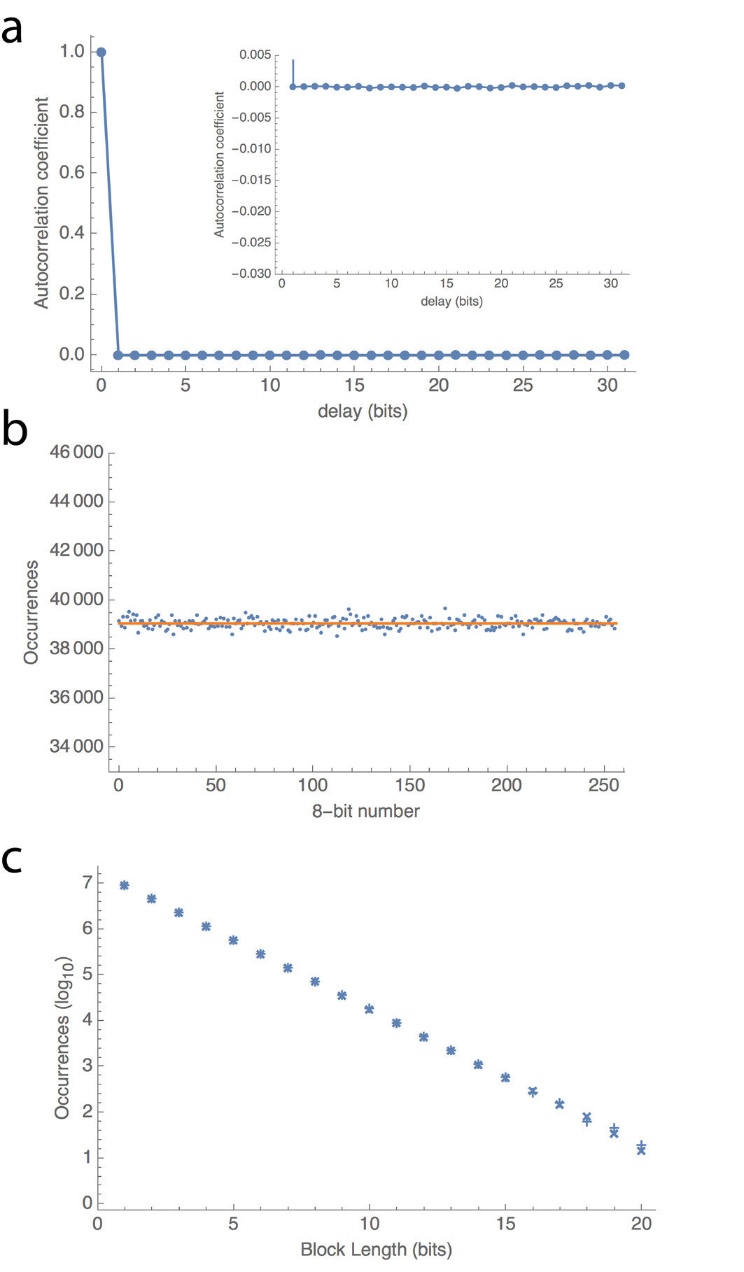
The tests described above are then applied to the post-processed sequence, which we denote as QRNG. For comparison, a sequence of equal length obtained from the Marsaglia CD-ROM Marsaglia95 was also tested. The sequence was generated using a combination of pseudorandom number generators. We denote this sequence as PRNG. A summary of the results are given in Tab. 1, where we have also included the results from the quantum photonic implementation of Ref. Jenn00 . The detailed results for the QRNG sequence are shown in Fig. 3. There is clearly an improvement that can be seen in the results of the tests. The autocorrelation varies by a maximum of over the bit delay range, the distribution of bytes is markedly improved and the distribution of block lengths of zeros and ones match up for larger block sizes. As a further and more rigorous test we apply the NIST Statistical Test Suite (STS) to the QRNG and PRNG sequences. The NIST test suite is aimed at becoming the first industry standard for testing random numbers and a detailed description of the tests can be found in Ref. NIST . The PRNG sequence of 80 Mbits fails the NIST test suite (Longest Run and Overlapping Template tests are not passed), while the QRNG sequence passes all tests at the significance level, performing well compared to other quantum photonic-based implementations Her16 ; Stip07 ; Furst10 ; Sang14 ; Wei09 ; Nie14 ; Stip15 . A summary of the results of the NIST tests is given in Tab. 2. The Overlapping Template, Linear Complexity, Random Excursions and Random Excursions Variant tests were run on a set of 80 sequences of 1 Mbits in length. The remaining tests ran on 160 sequences of length 500 Kbits.
| Statistical Test | p-value | Prop/Thr | Pass |
|---|---|---|---|
| Frequency | Yes | ||
| Block Frequency | Yes | ||
| Cumulative sums | Yes | ||
| Runs | Yes | ||
| Longest Run | Yes | ||
| Rank | Yes | ||
| FFT | Yes | ||
| Non Overlapping Template | Yes | ||
| Overlapping Template | Yes | ||
| Universal | Yes | ||
| Approximate Entropy | Yes | ||
| Random Excursions | Yes | ||
| Random Excursions Variant | Yes | ||
| Serial | Yes | ||
| Linear Complexity | Yes |
Discussion.— In this work we demonstrated the generation of random numbers using a plasmonic beamsplitter operating in the quantum regime. The presence of a plasmonic excitation in a given output from the beamsplitter determined the value of a random bit generated from a quantum scattering process. Using a stream of single plasmons we achieved a quantum random number generation rate of 2.37 Mbits/s, despite the presence of loss in the waveguides. We characterised the quality of the random number sequence generated and with post-processing found it to be comparable in quality to sequences from other photonic-based devices. Higher generation rates in our setup may be achieved in a number of ways: the use of detectors with reduced deadtimes Furst10 , operating several beamsplitters in parallel and including additional degrees of freedom such as the excitation arrival time Her16 ; Stip15 . Improvements in the fabrication of the beamsplitter would also reduce the bias between ones and zeros, and together with detector improvements would remove the need for post-processing which adds an additional resource overhead. The compact nature of the beamsplitter makes it suitable for integration in a variety of on-chip applications, such as in quantum computing and communication schemes. Future work into the integration of high quality sources and detectors on-chip would enable a fully self-contained device for use in a range of applications where true random number generation is required.

Acknowledgments.— We thank Francesco Petruccione, NTT-AT Japan and NT-MDT. This research was supported by the South African National Research Foundation, the National Laser Centre, the UKZN Nanotechnology Platform and the South African National Institute for Theoretical Physics. S.K.O acknowledges the support of Pennsylvania State University Materials Research Institute (MRI).
References
- (1) M. S. Tame, K. R. McEnery, Ş. K. Özdemir, S. A. Maier and M. S. Kim, Quantum Plasmonics, Nature Physics 9, 329 (2013).
- (2) J. Takahara, S. Yamagishi, H. Taki, A. Morimoto and T. Kobayashi, Guiding of a one-dimensional optical beam with nanometer diameter, Opt. Lett. 22, 475 (1997).
- (3) J. Takahara, in Plasmonic Nanoguides and Circuits (ed. Bozhevolnyi, S. I.) Ch. 2 (Pan Stanford Publishing, 2009).
- (4) S. Kawata, Y. Inouye and P. Verma, Plasmonics for near-field nano-imaging and superlensing, Nature Photonics 3, 388 (2009).
- (5) J. Homola, S. S. Yee and G. Gauglitz, Surface plasmon resonance sensors: review, Sensors and Actuators B 54, 3 (1999).
- (6) J. N. Anker, W. Paige Hall, O. Lyandres, N. C. Shah, J. Zhao and R. P. Van Duyne, Biosensing with plasmonic nanosensors, Nature Materials 7, 442 (2008).
- (7) E. Ozbay, Plasmonics: Merging photonics and electronics at nanoscale dimensions, Science, 311, 189 (2006).
- (8) C. M. Soukoulis and M. Wegener, Past achievements and future challenges in the development of three-dimensional photonic metamaterials, Nature Photonics 5, 523 (2011).
- (9) N. Meinzer, W. L. Barnes, and I. R. Hooper, Plasmonic meta-atoms and metasurfaces, Nature Photon. 8, 889 (2014).
- (10) S. Buckley, K. Rivoire and J. Vuckovic, Engineered quantum dot single-photon sources, Rep. Prog. Phys. 75, 126503 (2012).
- (11) I. Aharonovich, S. Castelletto, D. A. Simpson, C.-H. Su, A. D. Greentree and S. Prawer, Diamond-based single-photon emitters. Rep. Prog. Phys. 74, 076501 (2011).
- (12) A. V. Akimov, A. Mukherjee, C. L. Yu, D. E. Chang, A. S. Zibrov, P. R. Hemmer, H. Park, M. D. Lukin, Generation of single optical plasmons in metallic nanowires coupled to quantum dots. Nature 450, 402-406 (2007).
- (13) R. Kolesov, B. Grotz, G. Balasubramanian, R. J. St hr, A. A. L. Nicolet, P. R. Hemmer, F. Jelezko and J. Wrachtrup, Wave-particle duality of single surface plasmon polaritons. Nature Phys. 5, 470-474 (2009).
- (14) A. Huck, S. Kumar, A. Shakoor and U. L. Andersen, Controlled coupling of single nitrogen-vacancy center to a silver nanowire. Phys. Rev. Lett. 106, 096801 (2011).
- (15) A. Cuche, O. Mollet, A. Drezet and S. Huant, ‘Deterministic’ quantum plasmonics, Nano Letters 10 , 4566-4570 (2011).
- (16) D. E. Chang, A. S. S rensen, E. A. Demler, M. D. Lukin, A single-photon transistor using nanoscale surface plasmons. Nature Phys. 3, 807-812 (2007).
- (17) P. Kolchin, R. F. Oulton and X. Zhang, Nonlinear quantum optics in a waveguide: Distinct single photons strongly interacting at the single atom level. Phys. Rev. Lett. 106, 113601 (2011).
- (18) D. E. Chang, V. Vuletic and M. D. Lukin, Quantum nonlinear optics - photon by photon. Nature Photon. 8, 685-694 (2014).
- (19) J. O’Brien, A. Furusawa and J. Vuckovic, Quantum photonic technologies, Nature Photonics 3, 687-695 (2005).
- (20) G. Di Martino, Y. Sonnefraud, S. Kéna-Cohen, M. S. Tame, Ş. K. Özdemir, M. S. Kim and S. A. Maier, Quantum statistics of surface plasmon polaritons in metallic stripe waveguides, Nano Letters 12, 2504-2508 (2012).
- (21) R. W. Heeres, L. P. Kouwenhoven and V. Zwiller, Quantum interference in plasmonic circuits. Nature Nanotech. 8, 719-722 (2013).
- (22) J. S. Fakonas, H. Lee, Y. A. Kelaita and H. A. Atwater, Two-plasmon quantum interference. Nature Phot. 8, 317-320 (2014).
- (23) G. Di Martino, Y. Sonnefraud, M. S. Tame, S. Kéna-Cohen, F. Dieleman, Ş. K. Özdemir, M. S. Kim, S. A. Maier, Observation of quantum interference in the plasmonic Hong-Ou-Mandel effect. Phys. Rev. Applied 1, 034004 (2014).
- (24) Y.-J. Cai, M. Li, X.-F. Ren, C.-L. Zou, X. Xiong, H.-L. Lei, B.-H. Liu, G.-P. Guo and G.-C. Guo, High visibility on-chip quantum interference of single surface plasmons. Phys. Rev. App. 2, 014004 (2014).
- (25) G. Fujii, D. Fukuda and S. Inoue, Direct observation of bosonic quantum interference of surface plasmon polaritons using photon-number-resolving detectors. Phys. Rev. B 90, 085430 (2014).
- (26) E. Altewischer, M. P. van Exter and J. P. Woerdman, Plasmon-assisted transmission of entangled photons. Nature 418, 304-306 (2002).
- (27) S. Fasel, F. Robin, E. Moreno, D. Erni, N. Gisin and H. Zbinden, Energy-time entanglement preservation in plasmon-assisted light transmission. Phys. Rev. Lett. 94, 110501 (2005).
- (28) S. A. Maier, Plasmonics: Fundamentals and Applications, (Springer, New York, 2007).
- (29) A. González-Tudela, D. Martín-Cano, E. Moreno, L. Martin-Moreno, C. Tejedor and F. J. Garc a-Vidal, Entanglement of Two Qubits Mediated by One-Dimensional Plasmonic Waveguides. Phys. Rev. Lett. 106, 020501 (2011).
- (30) J. Hou, K. Słowik, F. Lederer and C. Rockstuhl, Dissipation-driven entanglement between qubits mediated by plasmonic nanoantennas. Phys. Rev. B 89, 235413 (2014).
- (31) C. Lee, M. Tame, C. Noh, J. Lim, S. A. Maier, J. Lee, D. G. Angelakis, Robust-to-loss entanglement generation using a quantum plasmonic nanoparticle array. New J. Phys. 15, 083017 (2013).
- (32) G. W. Hanson, S. A. H. Gangaraj, C. Lee, D. G. Angelakis, M. Tame, Quantum plasmonic excitation in graphene and robust-to-loss propagation. Phys. Rev. A 92, 013828 (2015).
- (33) W. Fan, B. J. Lawrie and R. C. Pooser, Quantum plasmonic sensing, Phys. Rev. A 92, 053812 (2015).
- (34) R. C. Pooser and B. Lawrie, Plasmonic Trace Sensing below the Photon Shot Noise Limit, ACS Photonics 3, 8 (2015).
- (35) C. Lee, F. Dieleman, J. Lee, C. Rockstuhl, S. A. Maier, M. S. Tame, Quantum plasmonic sensing: beyond the shot-noise and diffraction limit. ACS Photonics 3, 992 (2016).
- (36) M. Herrero-Collantes and J. C. Garcia-Escartin, Quantum random number generators, Rev. Mod. Phys. 89, 015004 (2017).
- (37) J. G. Rarity, P. C. M. Owens and P. R. Tapster, Quantum random number generation and key sharing, J. Mod. Opt. 41, 2435-2444 (1994).
- (38) A. Stefanov, N. Gisin, O. Guinnard, L. Guinnard and H. Zbinden, Optical quantum random number generator, J. Mod. Opt. 47, 595-598 (2000).
- (39) T. Jennewein, U. Achleitner, G. Weihs, H. Weinfurter and A. Zeilinger, A Fast and Compact Quantum Random Number Generator, Rev. Sci. Instrum. 71, 1675 (2000).
- (40) H.-Q. Ma, Y. Xie and L.-A. Wu, Random number generation based on the time of arrival of single photons, App. Opt. 44, 7760 (2005).
- (41) M. Stipčević and B. M. Rogina, Quantum random number generator based on photonic emission in semiconductors, Rev. Sci. Instrum. 78, 045104 (2007).
- (42) L. M. Yu, M. J. Yang, P. X. Wang and S. Kawata, Note: A sampling method for quantum random bit generation, Rev. Sci. Instrum. 81, 046107 (2010).
- (43) M. Furst, H. Weier, S. Nauerth, D.G. Marangon, C. Kurtsiefer and H. Weinfurter, High speed optical quantum random number generation, Opt. Exp. 18, 13029-13037 (2010).
- (44) M. Ren, E. Wu, Y. Liang, Y. Jian, G. Wu and H. Zeng, Quantum random-number generator based on a photon-number-resolving detector, Phys. Rev. A 83, 023820 (2011).
- (45) E. de J. Lopes Soares, F. A. Mendonca and R. V. Ramos, Quantum Random Number Generator Using Only One Single-Photon Detector, IEEE Phot. Tech. Lett. 26, 851-853 (2014).
- (46) B. Sanguinetti, A. Martin, H. Zbinden and N. Gisin, Quantum Random Number Generation on a Mobile Phone, Phys. Rev. X 4, 031056 (2014).
- (47) A. Khanmohammadi, R. Enne, M. Hofbauer and H. Zimmermanna, A Monolithic Silicon Quantum Random Number Generator Based on Measurement of Photon Detection Time, IEEE Phot. J. 7, 1-13 (2015).
- (48) S. Tisa, F. Villa, A. Giudice, G. Simmerle and F. Zappa, High-Speed Quantum Random Number Generation Using CMOS Photon Counting Detectors, IEEE J. Sel. Top. Quant. Electron. 21, 23-29 (2015).
- (49) D. Bonneau et al., Quantum interference and manipulation of entanglement in silicon wire waveguide quantum circuits, New J. Phys. 14 045003 (2012).
- (50) Y. Zhang et al., GaN directional couplers for integrated quantum photonics, Appl. Phys. Lett. 99, 161119 (2011).
- (51) J. Wang et al., Quantum photonic interconnect, Optica 3, 407-413 (2016).
- (52) C. Abellan et al., Quantum entropy source on an InP photonic integrated circuit for random number generation, Optica 3, 989 (2016).
- (53) B. Lamprecht, J. R. Krenn, G. Schider, H. Ditlbacher, M. Salerno, N. Felidj, A. Leitner, F. R. Aussenegg and J.-C. Weeber, Surface plasmon propagation in microscale metal stripes, App. Phys. Lett. 79, 51-53 (2001).
- (54) H. Ditlbacher, J. R. Krenn, G. Schider, A. Leitner and F. R. Aussenegg, Two-dimensional optics with surface plasmon polaritons, Appl. Phys. Lett. 81, 1762-1764 (2002).
- (55) R. Zia, M. D. Selker and M. L. Brongersma, Leaky and bound modes of surface plasmon waveguides, Phys. Rev. B 71, 165431 (2005).
- (56) J.-C. Weeber, M. U. González, A.-L. Baudrion, and A. Dereux, Surface plasmon routing along right angle bent metal strips, Appl. Phys. Lett. 87, 221101 (2005).
- (57) M. U. González, J.-C. Weeber, A.-L. Baudrion, A. Dereux, A. L. Stepanov, J. R. Krenn, E. Devaux and T. W. Ebbesen, Design, near-field characterization, and modeling of 45 degrees surface-plasmon Bragg mirrors, Phys. Rev. B 73, 155416 (2006).
- (58) V. A. Zenin, R. Malureanu, I. P. Radko, A. V. Lavrinenko and S. I. Bozhevolnyi, Near-field characterization of bound plasmonic modes in metal strip waveguides, Opt. Exp. 24, 4582 (2016).
- (59) S. M. Barnett, J. Jeffers, A. Gatti and R. Loudon, Quantum optics of lossy beam splitters, Phys. Rev. A 57, 2134 (1998).
- (60) D. Ballester, M. S. Tame and M. S. Kim, Quantum theory of surface plasmon polariton scattering, Phys. Rev. A 82, 012325 (2010).
- (61) J. Carolan, C. Harrold, C. Sparrow, E. Mart n-López, N. J. Russell, J. W. Silverstone, P. J. Shadbolt, N. Matsuda, M. Oguma, M. Itoh, G. D. Marshall, M. G. Thompson, J. C. F. Matthews, T. Hashimoto, J. L. O’Brien and A. Laing, Universal Linear Optics, Science 349, 711 (2015).
- (62) S. Clemmen, K. P. Huy, W. Bogaerts, R. G. Baets, P. Emplit and S. Massar, Continuous wave photon pair generation in silicon-on-insulator waveguides and ring resonators, Opt. Express 17, 16558 (2009).
- (63) A. L. Falk, F. H. L. Koppens, C. L. Yu, K. Kang, N. de Leon Snapp, A. V. Akimov, M.-H. Jo, M. D. Lukin and H. Park, Near-field electrical detection of optical plasmons and single-plasmon sources, Nature Physics 5, 475 (2009).
- (64) B. E. A. Saleh and M. C. Teich, Fundamentals of Photonics, 2nd edition, Wiley.
- (65) M. Stipčević and J. E. Bowers, Spatio-temporal optical random number generator, Opt. Exp. 23, 11619 (2015).
- (66) M. S. Tame and C. Lee and J. Lee and D. Ballester and M. Paternostro and A. V. Zayats and M. S. Kim, Single-photon excitation of surface plasmon polaritons, Phys. Rev. Lett. 101, 190504 (2008).
- (67) A. L. Edwards, The Correlation Coefficient, Ch. 4 in An Introduction to Linear Regression and Correlation. San Francisco, CA: W. H. Freeman, pp. 33-46 (1976).
- (68) M. Stipčević and R. Ursin, An On-Demand Optical Quantum Random Number Generator with In-Future Action and Ultra-Fast Response, Sci. Rep. 5 10214 (2015).
- (69) J. von Neumann, Various techniques used in connection with random digits, National Bureau of Standards Applied Mathematics Series 12, 36-38 (1951).
- (70) Y. Peres, Iterating Von Neumann’s Procedure for Extracting Random Bits, Annals of Statistics 20, 590-579 (1992).
- (71) G. Marsaglia, The Marsaglia Random Number CDROM, Department of Statistics and Supercomputer Computations Research Institute, Florida State University (1995). Available at http://stat.fsu.edu/pub/diehard.
- (72) NIST STS test available at https://code.google.com/archive/p/ randomnumbertestsuite-nist.
- (73) W. Wei and H. Guo, Bias-free true random-number generator, Opt. Lett. 34, 1876 (2009).
- (74) Y.-Q. Nie, H.-F. Zhang, Z. Zhang, J. Wang, X. Ma, J. Zhang and J.-W. Pan, Practical and fast quantum random number generation based on photon arrival time relative to external reference, Appl. Phys. Lett. 104, 051110 (2014).
- (75) M. Sýs, Z. Říha, V. Matyáš, K. Márton, A. Suciu, On the Interpretation of Results from the NIST Statistical Test Suite, Romanian Journal of Information Science and Technology 18, 18-32 (2015).