Flat Engineered Multi-Channel Reflectors
Abstract
Recent advances in engineered gradient metasurfaces have enabled unprecedented opportunities for light manipulation using optically thin sheets, such as anomalous refraction, reflection, or focusing of an incident beam. Here we introduce a concept of multi-channel functional metasurfaces, which are able to control incoming and outgoing waves in a number of propagation directions simultaneously. In particular, we reveal a possibility to engineer multi-channel reflectors. Under the assumption of reciprocity and energy conservation, we find that there exist three basic functionalities of such reflectors: Specular, anomalous, and retro reflections. Multi-channel response of a general flat reflector can be described by a combination of these functionalities. To demonstrate the potential of the introduced concept, we design and experimentally test three different multi-channel reflectors: Three- and five-channel retro-reflectors and a three-channel power splitter. Furthermore, by extending the concept to reflectors supporting higher-order Floquet harmonics, we forecast the emergence of other multiple-channel flat devices, such as isolating mirrors, complex splitters, and multi-functional gratings.
I Introduction
Recently, it was shown that thin composite layers (called metasurfaces) can operate as effective tools for controlling and transforming electromagnetic waves, see review papers Gly ; Hol_review ; Shalaev_review ; Capasso_review ; my_review ; Mohammad324 . A number of fascinating and unique functionalities have been realized with the use of thin inhomogeneous layers, such as anomalous refraction capasso , reflection sun ; bozh1 , focusing capassonew , polarization transformation Niemi , perfect absorption absor11 , and more Gly . In particular, significant progress has been achieved in controlling reflections of plane waves using structured surfaces.
Methods for engineering single-channel reflections (when a single plane wave is reflected into another single plane wave) are known. According to the reflection law, light impinging on a flat and smooth (roughness is negligible at the wavelength scale) mirror is reflected into the specular direction. It is simple to show that if there are induced electric or magnetic surface currents at the reflecting boundary, the conventional reflection law, in general, does not hold when the surface properties (e.g., surface impedance) smoothly vary within the wavelength scale. Proper engineering of the induced surface current gradients enables reflection of the incident light in a direction different from the specular one. This approach applied to metasurfaces was exploited recently in capasso and formulated as the generalized law of reflection. It was shown that the desired current gradient can be engineered using a metasurface realized as arrays of specifically designed sub-wavelength antennas. A large variety of metasurface designs for reflection control with different power efficiency levels were reported (e.g., sun ; bozh1 ; bozh2 ; mosall2 ; nanotechnology ; prx4 ; veysi ; functional ; li ). More recently, it was shown that parasitic reflections in undesired directions, inevitable in the designs based on the generalized reflection law capasso , can be removed synthesis ; last via engineering spatial dispersion in metasurfaces ana .
While the recently developed anomalously reflecting metasurfaces greatly extend the functionalities of conventional optical components such as blazed gratings handbook , all these devices are designed to control and manipulate incident fields of only one specific configuration. For example, metasurface reflectors sun ; bozh1 and blazed gratings grating1 ; grating2 ; retro1 refract/reflect a plane wave incident from a specific direction into another plane wave propagating in the desired direction.
Recently, a possibility of multi-functional performance using several parallel metasurfaces each performing its function at its operational frequency was considered in multi . Using a single metasurface, it is in principle possible to satisfy boundary conditions for more than one set of incident/reflected/transmitted waves if one assumes that the surface is characterized by a general bianisotropic set of surface susceptibilities karim . However, mathematical solutions for the required susceptibilities may lead to active, nonreciprocal or physically unrealizable parameter values karim .
In this paper, we propose flat metasurfaces with engineered response to excitations by plane waves coming from several different directions. As a particular conceptual example of realizable flat multi-channel devices, here we study multi-channel reflectors: Lossless reciprocal flat reflectors capable of simultaneous reflection control from and into several directions in space. We explore the possible functionalities of general surface-modulated flat reflectors. To this end, we characterize an arbitrary flat periodically modulated reflector using Floquet harmonics as a multi-channel system and inspect all allowed reflection scenarios under the assumption of lossless and reciprocal response. We analyze the reflector response in the framework of conventional scattering matrix notations. We find that in the case of periodic reflectors described by a scattering matrix (three-channel reflectors), there are devices with three basic functionalities: General specular reflectors, anomalous mirrors, and three-channel retro-reflectors. Moreover, response of an arbitrary multi-channel () reflector can be described by a combination of these basic functionalities. Although this general classification reveals all possible functionalities available with periodic reflectors, it does not provide a recipe for designing a metasurface with specific properties. To this end, exploiting the general surface impedance model synthesis , we rigorously design a three-channel retro-reflector and experimentally verify its electromagnetic response. Furthermore, we synthesize two other multi-channel devices: A beam splitter that is matched to the normally incident wave and a five-channel retro-reflector. We expect that the developed theory and realizations of multi-channel flat reflectors lead to more sophisticated thin and flat -channel metadevices, such as power dividers, directional couplers, interferometers or multi-channel filters for a broad range of frequencies.
II Multi-channel paradigm of flat reflectors
II.1 Definitions and notations
In general, reflection from planar surfaces can be controlled by surface structuring either on the wavelength scale (conventional diffraction gratings) or on the sub-wavelength scale (metasurface-based gratings). Operational principles of metasurface-based gratings differ from those of conventional blazed gratings comparison . The former rely on proper phase gradient formed by sub-wavelength scatterers, while the latter operate due to constructive interference of the rays reflected/refracted from different grooves. Planar topology of metasurface gratings is an important advantage in fabrication and in some applications. Here we explore the design flexibility offered by the metasurface paradigm.
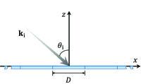
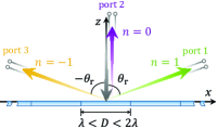
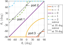
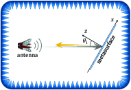
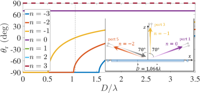
Let us consider a periodic metasurface in free space illuminated by a plane wave at an angle as shown in Fig. 1. Reflection from a periodic structure, in general, can be represented as interference of the infinite number of propagating and evanescent plane waves (Floquet harmonics). Here, fully reflecting surfaces (no transmission through the metasurface) are studied. The tangential wavenumber of a reflected harmonic of order is related to the incident wave wavenumber and to the period of the structure as . The corresponding normal wavenumber of the -th harmonic indicates whether it is a propagating or evanescent wave. Figure 2 shows the normal component of the reflected wave vector of all possible propagating modes from a flat reflector (for simplicity the incident angle is assumed) with respect to the period . The reflection angle of the corresponding harmonics is shown in Fig. 2.
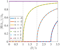
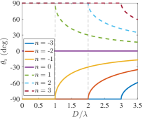
The operation of the reflector strongly depends on the periodicity. To highlight it, we divide the plots in Fig. 2 into three characteristic regions using vertical dashed lines. The first region corresponds to reflectors with the periodicity smaller than the wavelength . Such reflectors (e.g., most natural materials, uniform antenna arrays and metasurfaces) illuminated normally exhibit only the usual mirror reflection (harmonic ). The second region corresponds to flat reflectors with the period . Under normal illumination, they may provide anomalous reflection into the or directions (harmonics and , respectively). Hereafter, we adopt the usual convention of counting counter-clockwise and clockwise from the -axis (as shown in Fig. 1). Most of the recently proposed gradient metasurface reflectors capasso ; sun ; bozh1 ; bozh2 ; mosall2 ; nanotechnology ; prx4 ; veysi ; functional ; li ; synthesis ; Alu ; last ; ana operate in this periodicity region. Reflectors with the periodicity (the third region) illuminated normally have more than three “open” channels for propagating reflected waves. Reflectors operating in this region were not widely studied mainly due to the more complicated design procedures (more channels where uncontrolled reflections occur become “open”). It should be noted that in the case of oblique incidence the number of propagating channels is generally different from that found for the normal incidence. For example, as it will be shown below, for a sub-wavelength periodicity more than one mode become propagating.
II.2 Fundamental classes of periodical reflectors
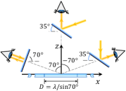
Here we explore to what extent and using what metasurface topologies it is possible to engineer reflections through all open channels, which are defined by the surface modulation period. As an example, let us first concentrate on “three-channel” reflectors because of their simple and concise analysis (reflectors with the higher number of channels are discussed in Section V). The three-channel regime can be realized in metasurfaces with a period if one of the channels corresponds to the normal incidence [see an illustration in Fig. 1]. It is convenient to represent the three propagation channels of this system as a three-port network using an analogy from the circuit theory. The channels are numbered according to Fig. 1. One can associate a scattering matrix with this system () which measures the ratio of the tangential electric field components (normalized by the square root of the corresponding impedance ) of the wave reflected into the -th channel when the reflector is illuminated from the -th channel smatrix , i.e., . Assuming that the reflector is reciprocal and lossless, we have two constraints on the scattering matrix: It must be equal to its transpose and unitary , where is the Kronecker delta, and the index notations are used.
II.2.1 General specular reflectors
Obviously, for a usual mirror made of perfect electric conductor (PEC), the scattering matrix [with ports defined as in Fig. 1] is anti-diagonal with all non-zero elements equal to the reflection coefficient of PEC, i.e., . Assuming possibly arbitrary reflection phases, in the most general form this matrix can be written as
| (1) |
Here and represent phases of ordinary reflections when the reflector is illuminated normally and obliquely at , respectively. The matrix satisfies both previously defined constraints. In contrast to usual metal mirrors, the reflection phase in gradient reflectors described by (1) can be engineered arbitrarily and independently for normal and oblique illuminations. In other words, there are no physical limitations that would forbid us from creating a reflector which, for example, operates as a metal mirror when illuminated normally and as a “magnetic” mirror magneticmirror when illuminated obliquely.
II.2.2 Anomalous reflectors
In the case of flat reflectors exhibiting ideal anomalous reflection ana , the scattering matrix can be fully determined using the symmetry constraints. Indeed, assuming that a normally illuminated reflector sends all the incident power to the channel and, reciprocally, power from channel to the normal direction, we immediately fix its response for illumination from channel. The scattering matrix in this scenario reads
| (2) |
where and are the phases of anomalous reflection and reflection for illumination from the channel, respectively.
As is seen from (2), the channel (port 3) is completely isolated from the other open channels of this metasurface. Incident light from the direction is always fully reflected back at the same angle. Moreover, no light from other directions can be reflected into this direction. This behaviour is imposed by the reciprocity and energy conservation. As an example, we consider the anomalous reflector proposed in ana which under normal illumination reflects 100% of power at . Figure 3 depicts the reflection angles for different propagating harmonics in this system versus the illumination angle . When the reflector is illuminated from port 1 or port 2, it creates an additional tangential momentum added to the incident wavevector , where . The grey dashed line denotes the specular reflection angles for an equivalent mirror tilted at (for such a mirror ). As is expected, the reflector imitates the behaviour of a titled mirror at two angles, when equals to and (marked by circles in the plot). Figure 3 illustrates this result by eyes of an external observer.
However, when (from port 3), the reflector emulates a mirror titled at (for such a mirror ) which corresponds to the solid grey line in Fig. 3. In this case the mode is evanescent (), while the mode becomes propagating and the reflector creates a negative tangential momentum responsible for retroreflection. Thus, an external observer looking at the reflector at would see his/her own image [see Fig. 3]. Experimental verification of this isolation property of the reflector proposed in ana is demonstrated in supplementary materials suppl . At all other angles, the reflection from the structure constitutes a combination of several harmonics whose amplitudes depend on the specific design of the reflector. Interestingly, the isolation effect of anomalous reflectors was not widely discussed in literature. A recent study sun erroneously reports that when such a reflector is illuminated from port 3, it forms a surface wave bound to the reflector.
Likewise, the normally incident power can be redirected to the channel, yielding the scattering matrix
| (3) |
where and are the phases of anomalous reflection and reflection for illumination from the channel, respectively. It should be noted that scattering matrices (2) and (3) represent equivalent physical properties. Matrix (3) corresponds to the metasurface modelled by (2) but rotated by around the -axis.
II.2.3 Three-channel retro-reflectors
By analysing the structure of scattering matrices (1), (2) and (3), we can observe that one more matrix form with three non-zero components is possible, which satisfies the symmetry constraints of the reciprocity and energy conservation:
| (4) |
where denote independent reflection phases for different illumination angles. It is simple to check that all other tensor structures with three non-zero components are forbidden. Remarkably, the three classes of reflectors with scattering matrices defined by (1), (2) and (4) [matrix (3) is equivalent to (2)] constitute a peculiar basis of most general three-channel reflectors. From the physical point of view, the three elemental functionalities of these reflectors form a basis of all possible reflection functionalities achievable with such periodic flat structures. Moreover, it can be shown that the response of an arbitrary multi-channel () reflector can be described by a combination of the three basic functionalities: General specular, anomalous, and retro-reflection.
III Three-channel retro-reflector
A closer look at scattering matrix (4) of a three-channel retro-reflector reveals that it corresponds to a so-called “isolating” mirror: In contrast to the previously considered structures, here all three channels are isolated from one another. This retro-reflector (or isolating mirror) under the assumption of lossless response represents a sub-wavelength blazed grating in the Littrow mount grating1 ; grating2 ; retro1 . Conventional realizations of Littrow gratings employ triangular or binary groove profiles with the total thickness of several wavelengths (metallic or dielectric gratings) retro1 ; retro2 ; retro3 . While this thickness is practically acceptable for optical gratings, it becomes very critical for their microwave counterparts resulting in several-centimeters-thick structures. Therefore, for microwave and radio frequency applications there is a need in sub-wavelength thin designs. A good candidate for low-frequency multi-channel mirrors are flat reflectarray antennas of slim profile encinar . However, to the best of our knowledge, there is only one work devoted to the design of flat reflectarrays comprising a dense array of sub-wavelength resonators redirecting energy in the direction of incidence fromana , and the isolating nature of the system was not explored in this work. In comparison, traditional retro-directive array antennas typically use a half-wavelength element spacing. In addition, they employ a collection of delay lines in passive designs or an active phase-conjugating circuitry in active designs behind the array plane Miyamoto . Therefore, we next rigorously design a flat three-channel retro-reflector (isolating mirror) and experimentally investigate its response from all three open-channel directions.
Here, the general approach synthesis based on the surface impedance concept is used. The design methodology starts with the definition of the total fields at the metasurface plane that ensure the desired functionality of port 3 (alternatively, it could be port 1). We require that no evanescent waves are excited for illumination from port 3 and the reflection constitutes a single plane wave. Considering as an example the TE polarization (electric field polarized along the -axis), one can relate the tangential total electric and magnetic fields through the surface impedance :
| (5) |
where and are the amplitudes of the incident and reflected waves at port 3, and is the intrinsic impedance in the background medium. Ensuring that all the input energy is reflected back into the same direction , the surface impedance reads . Such surface impedance can be realized as a single-layer structure. According to the theory of high-impedance surfaces Sievenpiper , an arbitrary reactive surface impedance can be achieved using a capacitive metal pattern separated from a metal plane by a thin dielectric layer. Since the cotangent function repeats with a period , the periodicity of this impedance profile is . This analytical solution gives periodicity smaller than the wavelength if port 3 is at an angle from the normal. It should be noted that the derived impedance expression is somewhat similar to that for conventional reflectarrays obtained in ana . This similarity appears because both formulas were derived under the assumption that the metasurface possesses local electromagnetic response.
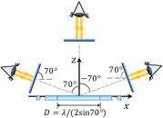
For the actual implementation, we design a three-port retro-reflector whose ports 1, 2, and 3 are directed at angles , , and , respectively [see Fig. 1]. Due to the sub-wavelength periodicity imposed on the system, port 2 is isolated from the other two ports. The functionality of port 1, in the absence of dissipation loss, is automatically satisfied because of the reciprocity of the system. The same scenario occurs in lossless blazed gratings in the Littrow mount grating1 ; grating2 ; retro1 . Interestingly, if the metasurface is lossy, this conclusion is not generally correct and reflections in port 1 and port 2 in principle could be tuned differently and independently. Note that there are other possible solutions for lossless isolating mirrors with periodicity , however, they imply excitation of evanescent waves when the illumination is from either of the three channels, which complicates the theoretical analysis.
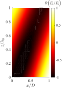
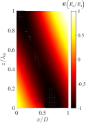
Figure 4 shows numerical simulations HFSS of a retro-reflector modelled as an ideal inhomogeneous sheet with the surface impedance calculated from Eq. 5. Figures 4(a–c) depict the real part of the scattered electric field (the instantaneous value), while Figs. 4(d–f) show the amplitude of this field. When the metasurface is illuminated from port 3 [see Figs. 4 and 4], a perfect reflected plane wave (no evanescent waves) is generated in the same direction, fulfilling the design condition. Figures 4 and 4 show the scattered electric fields when the metasurface is illuminated at and , respectively. Likewise, in these scenarios the incident wave is fully reflected back at the same angle. However, as it is seen from Figs. 4 and 4, evanescent fields naturally appear in order to satisfy the boundary conditions at the metasurface.
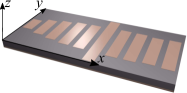
The purely imaginary surface impedance facilitates simple implementation of our design using conventional techniques. For demonstration purpose, we implement a three-port isolating mirror in the microwave regime () using rectangular conducting patches over a metallic plane separated by a dielectric substrate [see Fig. 5].
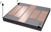
Each unit cell consists of five patches with the same width of and different lengths aligned along the line. The dimensions of the unit cell are mm and mm along the -axis and -axis, respectively. For designing the array, each patch was placed in a homogeneous array of equivalent patches and the length was calculated to ensure the reflection phase dictated by the surface impedance of the system. Although the efficiency of the metasurface synthesized using this approach was high (about 90% of retro-reflection in each channel), it was subsequently improved by numerical post-optimization of the patch dimensions. The numerically calculated efficiency of retro-reflection of the final metasurface is 92.8%, 95.4%, and 94.3% when excited from ports 1, 2, and 3, respectively. The rest of the energy is absorbed in the metasurface. The final lengths of the patches are , , , , and (listed along the -axis). The substrate material between the patches and the metallic plane is Rogers 5880 (, ) with thickness ( at 8 GHz). Figure 6 presents the results of numerical simulations of the final design.
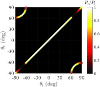
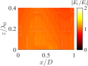
The colour map represents the normalized reflected power into the direction when the system is illuminated from the direction. We can clearly identify the directions of the three open channels as the light coloured regions when . From the colour map one can see that the metasurface reflects energy back in the diffracted (non-specular) direction when illuminated not only at , but in the range of angles from around to (the amount of this energy decreases when deviates from ). For example, when , about 88.8% is diffracted back at the angle . Such diffraction regime resembles reflection from a metal mirror tilted at (to be precise, this mirror would have some curvature since ). Extending the previously shown explanations, Figure 6 schematically represents the appearance of the flat three-channel isolating mirror for an external observer. For simplicity, the curvature of the equavalent mirrors tilted at is omitted in the illustration. Looking along any of the three directions of open channels, the observer always will “see” a mirror orthogonal to the observation direction. Notice that in contrast to conventional blazed gratings whose design procedure based on the coupled-mode theory is approximate and requires heavy post-optimization, our synthesis method provides a straightforward and rigorous solution (an exception is work retro3 which appeared during the review process of the current paper).
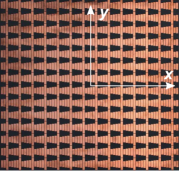
The metasurface sample was manufactured using the conventional printed circuit board technology and comprised unit cells in the -plane [see Fig. 5] with the total dimensions of mm and mm along the and axes, respectively. The experiment was performed in an anechoic chamber emulating the free-space environment. The orientation of the sample, defined by the angle , was controlled by a rotating platform as shown in Fig. 7.
The sample was illuminated by a quad-ridged horn antenna (11 dBi gain at 8 GHz) which was located at a distance of 5.5 m (about ) from the sample and also played the role of a receiving antenna. To filter out parasitic reflections from the chamber walls and antenna cables, the conventional time gating post-processing technique was exploited. In order to find the reflection efficiency of the sample, defined as the ratio of the incident and reflected power densities, we measured the received signal from the sample and then normalized it by the corresponding received signal from a reference uniform aluminium plate of the same cross section size.
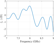
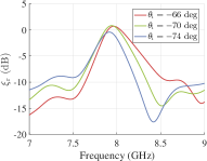
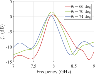
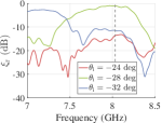
The measured reflection efficiency of the sample when it is illuminated normally (from port 2; ) is shown in Fig. 7. As it was discussed above, under the normal illumination the sub-wavelength periodicity of the metasurface allows only the propagating channel (specular reflection). Therefore, at the resonance frequency 8 GHz and below, the structure reflects back nearly all the incident power. Interestingly, at 8 GHz the reflection efficiency reaches 1.288 dB (135% of the power). This non-physical result is a consequence of the normalization error which wrongly implies that the currents induced at the metasurface and the reference metal plate should be equally uniform. More details on the proper normalization procedure in this case can be found in suppl . Figures 7 and 7 depict the reflection efficiency when the sample was illuminated at angles near the directions of the other two open channels . As is seen, there are strong peaks of reflection at 8 GHz: dB and dB for incidence at and , respectively. These results, with admissible measurement error level of 1 dB for such type of measurements, well confirm the high reflection efficiency of all channels predicted by the full-wave simulations.
IV Three-channel power splitter
To further illustrate the versatility of the proposed multi-channel paradigm, we synthesize a three-channel power splitter. The response of the splitter can be considered as a combination of two basic functionalities (anomalous reflections at two angles) dictated by (2) and (3). Beam splitters have been studied intensively in the form of diffraction gratings (see e.g., splitter1 ; splitter2 ), however, to the best of our knowledge, the possibility to tailor the proportion of power divided into different directions was not reported. Usually, the power is split equally between all channels. In contrast, our synthesis technique can be used to design a high-efficiency beam splitter with arbitrary energy distribution between the ports and arbitrary transmission phases. In the following example, we target a metasurface that under normal incidence splits incident energy towards , , and angles with the proportion 50:0:50. A metasurface with the same functionality and designed using the same design approach was recently proposed in splitter3 (only as a theoretical impedance sheet), but no physical implementation was demonstrated.
In our design, normally incident plane waves (from port 2) are split between ports 1 and 3 [see Fig. 1] without any reflection into port 2, i.e., port 2 is matched to the free-space wave impedance. Considering TE-polarized modes, we write the total tangential electric and magnetic fields on the reflecting surface at as
| (6) |
where , and , refer to the amplitudes and phases of the reflected waves at ports 1 and 3, respectively, and is the wavenumber of the reflected waves. Equal power division occurs when . Interestingly, if phases are chosen, the surface impedance becomes purely real, meaning that the the Poynting vector has only the normal component (negative or positive in different locations) at the impedance boundary. Designing a metasurface to implement this scenario is not straightforward with our approach which implies optimizing unit-cell elements to follow the imaginary part of the required surface impedance. Therefore, in our example, we choose reflection phases and to simplify the metasurface design. In this case, the corresponding surface impedance is expressed as
| (7) |
which is a periodic function with the period . Notice that this periodicity is the double of that in the previous example of an isolating mirror. The surface impedance is plotted in Fig. 8.
The surface resistance oscillates between positive and negative values, associated with locally lossy and active properties, respectively. Averaged over the period, the surface is in overall lossless.
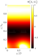
Instead of an inhomogeneous surface with locally active and lossy regions, the reflecting surface may be implemented as a strongly non-local lossless metasurface based on energy channelling along the surface ana ; last . Indeed, the surface impedance (7) has been derived assuming that there are only three plane waves propagating above the metasurface: A single incident and two reflected ones. This assumption is very limiting and in general can be relaxed by allowing evanescent waves generation at the interface. While they would not contribute to the far-field radiation, decaying quickly near the interface, their contribution to the total fields (6) at would ensure purely imaginary surface impedance at each point of the metasurface. Although analytical determination of the required set of evanescent waves is a complicated task, the solution can be obtained exploiting the concept of leaky-wave antennas ana . In this implementation, the energy received over the lossy region (where ) is carried by a surface wave propagating along the -axis before being radiated into space in the active region of the surface (where ). In what follows, we discard the real part of impedance (7) and numerically optimize HFSS the imaginary part of the impedance to ensure the desired amplitudes of the reflected plane waves. The optimized impedance profile (discretized into 15 elements with a uniform impedance) is shown by circle markers in Fig. 8. The numerically optimized impedance profile (the imaginary part) turns out to closely follow that of the active-lossy impedance dictated by (7).
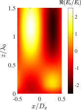
Fig. 8 depicts numerical results for the real part (the instantaneous value) of the normalized electric field reflected by the metasurface with the optimized impedance profile. An interference pattern between two plane waves propagating in the -plane towards the and directions with a phase difference is observed. As is expected, at the interface a set of evanescent fields is generated. The incident wave is split equally between ports 1 and 3 with 49.8% of incident power channelled into each direction.
Following the same implementation approach as for the three-channel isolating mirror, we use rectangular patches over a metallic ground plane. Ten equidistant patches with the same width of mm and different lengths were placed in each unit cell. As an initial estimation, the length of each patch was chosen in order to ensure the reflection phase described by the imaginary part of the optimized impedance when the patch is placed in a homogeneous array. After that, we built the unit cell consisting of ten patches and accurately tuned the lengths by using post-optimization for obtaining the best performance. The final lengths of the patches listed along the -direction are , , , , , , , , , and [see Fig. 9].
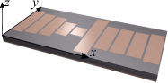
The dimensions of the unit cell are mm and mm along the -axis and -axis, respectively. The substrate material and patches material are the same as in the previous example. The numerical results indicate that normally incident power is split by the metasurface towards (port 3), (port 2), and (port 1) with the proportion . About 3.49% of incident power is absorbed in the metasurface due to material losses. When the splitter is illuminated from port 1 or 3, it is not matched to free space, and energy is split in all three ports with the proportion of (when illuminated from port 1) or (when illuminated from port 3). This result is not surprising and in agreement with the basic multi-port network theory which states that lossless passive three-port splitters matched at all ports cannot exist (since it would contradict the condition of unitary scattering matrix pozar ).
Next, we experimentally verify operation of the metasurface in an anechoic chamber. The metasurface sample consists of unit cells along the and axes, respectively. The overall dimensions of the sample along the and axes are mm and mm.
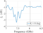
First, the sample was illuminated from the normal direction () by a horn antenna as is shown in Fig. 7, and the reflected signal was measured by the same antenna. Similarly to the experiment in the previous section, the signal was normalized by that of a reference uniform aluminium plate of the same size. The measured level of retro-reflection along direction is depicted in Fig. 10.
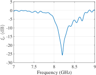
At the resonance frequency of 8.2 GHz, the measured curve has a deep drop, corresponding to reflected power of 0.3%. This result is in excellent agreement with the simulated data and confirms that the power splitter is well matched from port 2. A slight shift of the resonance frequency in the experiment can be explained by manufacturing errors and the tolerance of the substrate permittivity value.
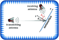
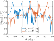
Next, it is important to verify that the splitter in fact reflects normally incident power equally towards and directions. For this purpose, we add a second (receiving) antenna to the experimental setup [see Fig. 10]. The position of the second antenna is determined by the angle . The distances from the metasurface center to the receiving and transmitting antennas were 2.1 m and 5.4 m, respectively. Figure 10 depicts the signal measured by the receiving antenna for two different positions of the antenna (when and ) versus the incidence angle . The red curve () has three distinct peaks. The central peak at corresponds to the case of normal incidence (from port 2) and strong reflection towards port 1 (). The peak at corresponds to excitation of the metasurface from port 3 and reflection towards port 2 (). The peak at appears due to specular reflection from the metasurface when it is illuminated not from its main ports. Three peaks of the blue curve for the case of can be explained likewise. Interestingly, the central peaks on the red and blue curves do not occur exactly at and there is a small shift between them. This result is expected and means that when the power splitter is illuminated at a small oblique angle, the reflection towards one direction increases at the expense of the decrease of reflection in the other direction. The total efficiency (sum of the normalized reflected power towards and directions) is maximum exactly when .
In order to calculate the power reflected by the metasurface towards and , we perform an additional measurement with a reference aluminium plate (position of the receiving antenna was at ). As is seen from Fig. 10, a specular reflection peak is detected by the antenna when the metal plate is oriented at . Following the procedure reported in ana , we calculate the reflection efficiency of the power splitter towards (for the red curve) and (for the blue curve) as
| (8) |
Here is a correction factor which gives the ratio between the theoretically calculated signal amplitudes from an ideal power splitter (of the same size and made of lossless materials) and a perfect conductor plate ana . Using this formula, the calculated reflection efficiencies towards and directions were found to be nearly equal to dB. In the linear scale and expressed in terms of power, the reflection efficiency towards each direction (ports 1 and 3) is about 48%. This result is in good agreement with the simulated data (45.74% and 49.71%).
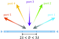
V Five-channel retro-reflector
In this section, we demonstrate that the concept of multi-channel flat reflectors can be extended to devices with more than three ports. In what follows, we synthesize a mirror which fully reflects incident waves back from five different directions. Since such functionality requires fast variations of the surface impedance over the sub-wavelength scale (due to excitation of required additional evanescent fields for satisfying the boundary condition), it is unattainable with conventional blazed gratings whose grooves are of the wavelength size. Designing conventional gratings with sub-wavelength-sized grooves is impractical with today’s nano-fabrication technologies.
In the case of the three-channel retro-reflector described above, engineering back reflections in one port automatically ensured proper response of the reflector in the other two ports (due to reciprocity and negligible dissipation). However, when the number of ports increases to five, one should design a metasurface with prescribed response for several different illuminations.
The directions of the five ports cannot be chosen arbitrary and can be determined using Floquet-Bloch analysis: , where is the number of the harmonic and is the reflection angle corresponding to the -th harmonic. There are two scenarios of retro-reflection in five ports. In the first scenario, the periodicity of the reflector is chosen to satisfy inequality . In this case, all the five ports are “open” when the reflector is illuminated from any of them. The directions of the five ports are given by , where .
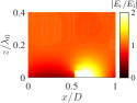
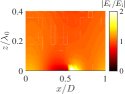
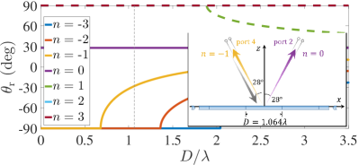
In the second scenario, the reflector periodicity is chosen so that . Here, at normal illumination , only three ports are open: At angles and [see Fig. 2], where subscript indices correspond to the harmonic number . The same ports remain open also in the case when [see Fig. 11 where is chosen as an example]. However, illuminated from , the metasurface has only two open ports corresponding to , as is shown in Fig. 11. Thus, although the retro-reflector has five channels, three of its channels are isolated from two others.
Both scenarios of the retro-reflector provide similar response for the illuminations of the five channels. For our design we use the second scenario since it requires to ensure retro-reflection only in three ports (response in others will be automatically satisfied due to reciprocity). We choose periodicity so that the five ports are directed at , , and from the normal.
It can be shown that an ideal five-channel retro-reflector illuminated from either channel necessarily generates evanescent waves. Analytical determination of these required evanescent waves is a complex problem and could be a subject for a separate study. Next, we firstly design a metasurface for retro-reflection when illuminated from directions and then exploit numerical post-optimization to gain proper response in the other channels.
As the first approximation, we synthesize the metasurface to fully reflect incident waves from at angle . This case is similar to that considered above in Section III and, therefore, the impedance profile can be calculated using Eq. (5). The obtained metasurface rigorously works as a retro-reflector from ports 2 and 4 [see ports notations in Fig. 11], while it produces parasitic energy coupling to ports 1 and 5 when excited from the normal direction (port 3). Next, we numerically optimize HFSS the obtained impedance profile to ensure maximized back reflection (retro-reflection) in all the ports. The optimized unit cell of the metasurface is shown in Fig. 9 and contains ten patches with the following lengths listed along the -direction: , , , , , , , , , and . The unit cell dimensions are the same as those of the three-channel power splitter considered above. The width of the patches is 3.49 mm. The numerically obtained results can be represented by the following matrix (at 8 GHz)
| (9) |
where characterizes the ratio of power reflected into the -th port when the metasurface is illuminated from the -th port [see definitions of the ports in Fig. 11]. As is seen, for illumination from either port, the metasurface effectively reflects energy back in the incident direction with the average efficiency of , i.e. for . The non-ideal operation can be improved further by increasing discretization of the unit cell.
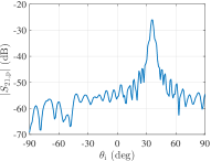
Next, we fabricated a metasurface sample with the same dimensions as those presented in Section IV. The experimental setup was identical to that shown in Section III for a three-channel retro-reflector. Figure 12 shows the measured efficiency of back reflection (retro-reflection) when the metasurface is illuminated at , , and .
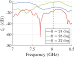
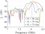
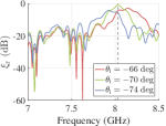
At the frequency of 8.03 GHz, retro-reflection in all channels is high and nearly equal. To compare the measured results at 8.03 GHz with the simulated ones, we write them in the matrix form similar to (9):
| (10) |
Here the dotes denote unknown values that were not measured in the experiment. The values at the main diagonal represent reflection efficiencies (into the -th port) expressed in the linear scale for illumination from the same -th port. As can be seen, the simulated and measured results in (9) and (10) are in good agreement.
VI Discussions and conclusions
To summarize, combining the microwave circuit and diffraction gratings theories, we proposed a concept of flat engineered multi-channel reflectors. We revealed the existence of three basic functionalities available with general flat reflectors: General specular, anomalous, and retro- reflections. Next, we designed three different multi-channel devices whose response can be described by a combination of these basic functionalities.
As was demonstrated, proper engineering the periodicity and surface impedance of a metasurface enables straightforward design of various multi-channel reflectors. Indeed, with the increase of the period the number of “open” channels grows (see Fig. 2), leading to great design freedom. One example of possible multi-channel reflector device is a -port isolating mirror (flat retro-reflector) depicted in Fig. 13.
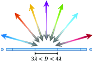
All the channels (in principle, the number of channels can be very big) of this mirror are isolated from one another and, therefore, the mirror illuminated at almost any angle would fully reflect energy back to the source. Such a mirror would possess unprecedented physical properties: Observers standing around the mirror would see only images of themselves but not other observers. In fact, the question of what exactly an observer would see in this mirror is not straightforward and strongly depends on the number of the “open” channels and their isolation efficiency.
Alternatively, large periodicity of the reflector could be used to combine different functionalities in one reflector or even to overcome the design limitations of three-channel structures. Figure 13 demonstrates a beam splitter which at the same time acts as a mirror at other angles. Modifying the response from ports 1 and 5, one can greatly extend the properties which the reflector exhibits when excited from ports 2–4. For the sake of simplicity, in this paper we confined our design of multi-channel reflectors to the case when one of the channels corresponds to the normal plane-wave incidence even though the proposed metasurfaces operate also at oblique angles. The scenario with the normal incidence channel being closed further extends design possibilities, but we do not consider this case here.
Other exciting functionalities become possible by extending the multi-channel paradigm in three other directions: Partially transparent films (additional channels appear in transmission), multi-channel polarization transformers, and non-periodical structures (e.g., to emulate a convex or spherical mirror response using a single flat surface).
Acknowledgements.
This work was supported in part by the Nokia Foundation and the Academy of Finland (project 287894). The authors would like to thank Muhammad Ali and Abbas Manavi for technical help with the experimental equipment.References
- (1) S. B. Glybovski, S. A. Tretyakov, P. A. Belov, Y. S. Kivshar, and C. R. Simovski, Metasurfaces: From microwaves to visible, Phys. Rep. 634, pp. 1–72, (2016).
- (2) C. L. Holloway, E. F. Kuester, J. A. Gordon, J. O’Hara, J. Booth, and D. R. Smith, An overview of the theory and applications of metasurfaces: The two-dimensional equivalents of metamaterials, IEEE Antennas Propag. Mag. 54, 2 (2012).
- (3) A. V. Kildishev, A. Boltasseva, and V. M. Shalaev, Planar photonics with metasurfaces, Science 339, 6125 (2013).
- (4) N. Yu and F. Capasso, Flat optics with designer metasurfaces, Nat. Mater. 13, 2 (2014).
- (5) S. A. Tretyakov, Metasurfaces for general transformations of electromagnetic fields, Phil. Trans. R. Soc. A 373, 2049 (2015).
- (6) M. Albooyeh, S. Tretyakov, and C. Simovski, Electromagnetic characterization of bianisotropic metasurfaces on refractive substrates: General theoretical framework, Annalen der Physik 528, 721 (2016).
- (7) N. Yu, P. Genevet, M. A. Kats, F. Aieta, J.-P. Tetienne, F. Capasso, and Z. Gaburro, Light propagation with phase discontinuities: Generalized laws of reflection and refraction, Science 334, 333 (2011).
- (8) S. Sun, K.-Y. Yang, C.-M. Wang, T.-K. Juan, W. T. Chen, C. Y. Liao, Q. He, S. Xiao, W.-T. Kung, G.-Y. Guo, L. Zhou, and D. P. Tsai, High-efficiency broadband anomalous reflection by gradient meta-surfaces, Nano Lett. 12, 6223 (2012).
- (9) A. Pors, M. G. Nielsen, R. L. Eriksen, and S. I. Bozhevolnyi, Broadband focusing flat mirrors based on plasmonic gradient metasurfaces, Nano Lett. 13, 829 (2013).
- (10) M. Khorasaninejad, W. T. Chen, R. C. Devlin, J. Oh, A. Y. Zhu, and F. Capasso, Metalenses at visible wavelengths: Diffraction-limited focusing and subwavelength resolution imaging, Science 352, 6290 (2016).
- (11) T. Niemi, A. Karilainen, and S. Tretyakov, Synthesis of polarization transformers, IEEE Trans. Antennas Propag. 61, 6 (2013).
- (12) Y. Ra’di, V. S. Asadchy, and S. Tretyakov, Total absorption of electromagnetic waves in ultimately thin layers, IEEE Trans. Antennas Propag. 61, 9 (2013).
- (13) A. Pors and S. I. Bozhevolnyi, Plasmonic metasurfaces for efficient phase control in reflection, Opt. Express 21, 27438 (2013).
- (14) M. Farmahini-Farahani and H. Mosallaei, Birefringent reflectarray metasurface for beam engineering in infrared, Opt. Lett. 38, 462 (2013).
- (15) M. Esfandyarpour, E. C. Garnett, Y. Cui, M. D. McGehee, and M. L. Brongersma, Metamaterial mirrors in optoelectronic devices, Nat. Nanotechnol. 9, 542 (2014).
- (16) M. Kim, A. M. H. Wong, and G. V. Eleftheriades, Optical Huygens’ metasurfaces with independent control of the magnitude and phase of the local reflection coefficients, Phys. Rev. X 4, 041042 (2014).
- (17) M. Veysi, C. Guclu, O. Boyraz, and F. Capolino, Thin anisotropic metasurfaces for simultaneous light focusing and polarization manipulation, Journ. Opt. Soc. Am. B 32, 2 (2015).
- (18) V. S. Asadchy, Y. Radi, J. Vehmas, and S. A. Tretyakov, Functional metamirrors using bianisotropic elements Phys Rev. Lett 114, 095503 (2015).
- (19) Z. Li, E. Palacios, S. Butun, and K. Aydin, Visible-frequency metasurfaces for broadband anomalous reflection and high-efficiency spectrum splitting, Nano Letters 15, 3 (2015).
- (20) V. S. Asadchy, M. Albooyeh, S. N. Tcvetkova, A. Díaz-Rubio, Y. Ra’di, and S. A. Tretyakov, Perfect control of reflection and refraction using spatially dispersive metasurfaces, Phys. Rev. B. 94, 075142 (2016).
- (21) A. Epstein and G. V. Eleftheriades, Synthesis of passive lossless metasurfaces using auxiliary fields for reflectionless beam splitting and perfect reflection, Phys. Rev. Lett. 117, 25 (2016).
- (22) A. Díaz-Rubio, V. S. Asadchy, A. Elsakka, and S. A. Tretyakov, From the generalized reflection law to the realization of perfect anomalous reflectors, arXiv:1609.08041v1 (2016).
- (23) C. A. Palmer and E. G. Loewen, Diffraction Grating Handbook (Newport Corporation, New York, 2005).
- (24) A. Bunkowski, O. Burmeister, T. Clausnitzer, E.-B. Kley, A. Tünnermann, K. Danzmann, and R. Schnabel, Optical characterization of ultrahigh diffraction efficiency gratings, Appl. Opt. 45, 23 (2006).
- (25) N. Destouches, A. V. Tishchenko, J. C. Pommier, S. Reynaud, O. Parriaux, S. Tonchev, and M. A. Ahmed, 99% efficiency measured in the -1st order of a resonant grating, Opt. Express 13, 9 (2005).
- (26) Z.-L. Deng, S. Zhang, and G. P. Wang, A facile grating approach towards broadband, wide-angle and high-efficiency holographic metasurfaces, Nanoscale 8, 3 (2016).
- (27) A. A. Elsakka, V. S. Asadchy, I. A. Faniayeu, S. N. Tcvetkova, and S. A. Tretyakov, Multifunctional cascaded metamaterials: Integrated transmitarrays, IEEE Trans. Antennas Propag. 64, 4266 (2016).
- (28) K. Achouri, M. A. Salem, and C. Caloz, General metasurface synthesis based on susceptibility tensors, IEEE Trans. Antennas Propag. 63, 7 (2015).
- (29) A. L. Kitt, J. P. Rolland, and A. N. Vamivakas, Visible metasurfaces and ruled diffraction gratings: a comparison, Opt. Mater. Express 5, 12 (2015).
- (30) N. M. Estakhri and A. Alù, Wavefront transformation with gradient metasurfaces, Phys. Rev. X 6, 4 (2016).
- (31) A. Bunkowski, O. Burmeister, K. Danzmann, and R. Schnabel, Input–output relations for a three-port grating coupled Fabry-Perot cavity, Opt. Lett. 30, 10 (2005).
- (32) M. Esfandyarpour, E. C. Garnett, Y. Cui, M. D. McGehee, and M. L. Brongersma, Metamaterial mirrors in optoelectronic devices, Nat. Nanotechnol. 9, 7 (2014).
- (33) See supplementary materials.
- (34) M. Tymchenko, V. K. Gavrikov, I. S. Spevak, A. A. Kuzmenko, and A. V. Kats, Quasi-resonant enhancement of a grazing diffracted wave and deep suppression of specular reflection on shallow metal gratings in terahertz, Appl. Phys. Lett. 106, 261602 (2015).
- (35) N. M. Estakhri, V. Neder, M. W. Knight, A. Polman, and A. Alù, Visible light, wide-angle graded metasurface for back reflection, ACS Photonics 4, 2 (2017).
- (36) J. Huang and J. A. Encinar, Reflectarray Antennas (Wiley, New Jersey, 2008).
- (37) E. Doumanis, G. Goussetis, G. Papageorgiou, V. Fusco, R. Cahill, and D. Linton, Design of engineered reflectors for radar cross section modification, IEEE Trans. Antennas Propag. 61, 1 (2013).
- (38) R. Y. Miyamoto and T. Itoh, Retrodirective arrays for wireless communications, IEEE Microwave Magazine 3, 71 (2002).
- (39) D. Sievenpiper, L. Zhang, R. F. J. Broas, N. G. Alexopolous, and E. Yablonovitch, High-impedance electromagnetic surfaces with a forbidden frequency band, IEEE Trans. Microw. Theory Tech. 47, 11 (1999).
- (40) ANSYS HFSS 15: www.ansys.com.
- (41) R. Schnabel, A. Bunkowski, O. Burmeister, and K. Danzmann, Three-port beam splitters–combiners for interferometer applications, Opt. Lett. 31, 5 (2006).
- (42) W. Shu, B. Wang, H. Li, L. Lei, L. Chen, and J. Zhou, High-efficiency three-port beam splitter of reflection grating with a metal layer, Superlattice Microst. 85 (2015).
- (43) N. M. Estakhri and A. Alù, Recent progress in gradient metasurfaces, J. Opt. Soc. Am. B 33, 2 (2016).
- (44) D. M. Pozar, Microwave engineering 4th ed. (John Wiley & Sons, Hoboken, 2012).