Distortion and destruction of colloidal flocks in disordered environments
How do flocks, herds and swarms proceed through disordered environments? This question is not only crucial to animal groups in the wild, but also to virtually all applications of collective robotics, and active materials composed of synthetic motile units Handbook ; Nagpal2014 ; Berman ; Shklarsh ; Baush2010 ; Deseigne ; Thutupalli ; Dogic ; Bocquet ; Bricard2013 ; Palacci ; Bechinger ; Goldstein ; Sano2015 . In stark contrast, appart from very rare exceptions Peruani1 ; Olson2014 ; Quint , our physical understanding of flocking has been hitherto limited to homogeneous media Marchetti_review ; Vicsek_review ; Cavagna_review . Here we explain how collective motion survives to geometrical disorder. To do so, we combine experiments on motile colloids cruising through random microfabricated obstacles, and analytical theory. We explain how disorder and bending elasticity compete to channel the flow of polar flocks along sparse river networks akin those found beyond plastic depinning in driven condensed matter Reichhardt_Review . Further increasing disorder, we demonstrate that collective motion is suppressed in the form of a first-order phase transition generic to all polar active materials.
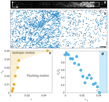
We use the experimental system introduced in Bricard2013 ; Bricard2015 , which consists in colloidal rollers powered by the so-called Quincke electro-rotation mechanism Quincke , see Methods and Supplementary Methods. The motile colloids experience both hydrodynamic and electrostatic interactions which promote alignement of their translational velocity Bricard2013 ; Bricard2015 . When the roller packing fraction, , exceeds , these polar interactions overcome rotational diffusion and macroscopic collective motion emerges Bricard2013 ; Bricard2015 . In the homogeneous slab geometry shown in Fig. 1a, a seven-millimeter-long flock spontaneously forms and cruises through a dilute ensemble of rollers moving isotropically, see Supplementary Video 1. The flock has a sharp front, a long tail, and endlessly cruises at a constant speed along the -axis, bouncing back and forth on the confining walls. The flock speed is found to be equal to the speed of an isolated roller .
Can flocks propagate in disorder media? How does this broken-symmetry phase survive to geometrical disorder? In order to answer these questions, we include randomly distributed circular obstacles of radius in the microfluidic channel. When the obstacle packing fraction is small, collective motion still emerges according to the same nucleation and propagation scenario, see Fig. 1b and Supplementary Video 2. However as exceeds a critical value, , the obstacle collisions suppress any form of global orientational order and macroscopic transport. Correlated motion persists only at short scales, as illustrated in Supplementary Video 3. As expected, dense flocks are more robust to disorder and monotonically increases with the roller fraction , Fig. 1c.
In all that follows, the sole control parameter of our experiments is the obstacle fraction . The roller fraction is set to a constant value above the flocking threshold in a obstacle-free channel, . A natural order parameter for the flocking transition is the magnitude of the roller current projected on the -axis, and averaged over time and space. Accordingly monotonically decreases with and vanishes at , Fig. 1d.
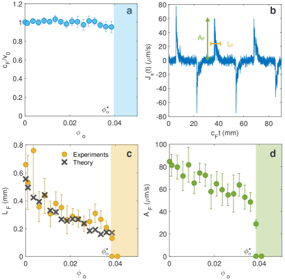
Our first goal is to elucidate this loss of orientational order. To do so, we consider the evolution of the flock morphology along the propagation direction upon increasing disorder. This morphology can be equivalently captured by the variations of the local density, current, or polarization fields as demonstrated in a Supplementary Note. For sake of clarity we focus here on the roller current as the main observable. The flock speed is unaltered by disorder and remains very close to the roller velocity for all , Fig. 2a. Therefore the time variations of , the longitudinal current averaged over the transverse direction, give an accurate description of the coarse-grained shape of the flocks, see Fig. 2b. Three important results are in order: the decrease of the flock length, , echoes that of the global order parameter and vanishes rather smoothly at , Fig. 2c. However, as shown in Fig. 2d, the maximal current amplitude, , undergoes a sharp drop and cancels discontinuously at . Finally, at , the flocks are intermittent: they repeatedly form and propagate steadily, before spontaneously vanishing and nucleating again. A featureless isotropic state coexists in time with a phase-separated flocking state where macroscopic excitations as large as propagate in the channel. Altogether these three observations firmly evidence that disorder suppresses the flocking state in the form of a first-order non-equilibrium transition.
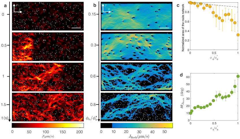
However, the obstacles do not merely reduce the extent of the flocks down to their extinction but also trigger qualitative changes in their inner structure. The snapshots of the roller current at four subsequent times in Fig. 3a demonstrate that the flocks are strongly heterogeneous spatial patterns, see also Supplementary Video 4. We characterize the local flock morphology by introducing the current field averaged over the time interval taken by the flock to cross the observation window. At low , we observe that colloid-depleted wakes as large as form downstream each obstacle, see Fig. 3b upper panel. However, as increases, the competition between alignment interactions and multiple-obstacle scattering, causes the redistribution of the roller current into a static river network, Fig. 3b. Virtually no collective motion occurs in the closed regions surrounded by the flowing rivers (black regions in Fig. 3b). The extent of the regions where the flow is suppressed can significantly exceed both the typical inter obstacle-distance and the depletion-wake size. Importantly, upon increasing , the river network becomes increasingly sparse and different from the region of space left around the mere superposition of uncorrelated wakes. Comparing the areas of these two very different geometries allows us to quantify the sparsity of the river networks in Fig. 3c. In addition, the networks also become increasingly tortuous as demonstrated by the fast increase of the orientational fluctuations of with in Fig. 3d. Above orientational order survives to disorder in finite and short-lived rivers. Any form of macroscopic transport is suppressed as these transient channels are isotropically distributed and do not percolate through the entire system, see Supplementary Video 3 and Supplementary Note. We close this discussion by stressing that these emergent river networks are strikingly similar to that encountered above the plastic depinning threshold when driving an ensemble of elastically-coupled particles through quenched disorder (from vortex lattices in type-II superconductors, to driven colloids and grains) Jensen88 ; Gronbech96 ; Troyanovski99 ; Ledoussal98 ; Faleski96 ; Topinka2001 ; Pertsinidis2008 ; Reichhardt_Review ; Wyart2015 .
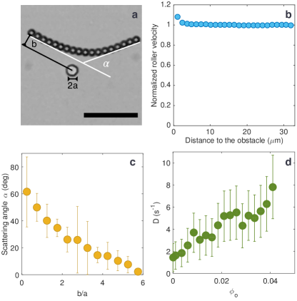
In order to elucidate the physics underlying the suppression of collective motion and the emergence of channelling networks, we first need a quantitative description of the roller-obstacle interactions. As a roller approaches an obstacle its direction of motion is repelled at a distance yet its speed remains unchanged, Figs. 4a and 4b. The roller-obstacle and roller-roller repulsions stem from the same physical mechanisms Bricard2013 : a dielectric obstacle causes a local radial perturbation of the electric field used to power the Quincke rotation. As a result, a short-range repulsive torque reorients the roller velocity in the direction opposite to the obstacle, see Supplementary Note. This interaction has the same symmetry as that numerically considered in Peruani1 ; Peruani2 . The scattering plots shown in Fig. 4c and Supplementary Note, demonstrate that the repulsive torques are weak and short ranged. A head-on collision merely deflects the initial roller orientation by an angle of . As a consequence, up to , the trajectories in the isotropic phase remain diffusive at long times, and are fully characterized by their rotational diffusivity , which linearly increases with , Fig. 4d.
We can now account for the first-order nature of the flocking transition. The linear increase of suggests simplifying the interactions between the rollers and the obstacles as uncorrelated binary collisions with random scatterers Peruani2 . Within this Boltzmann approximation, we can generalize the kinetic theory valid at the onset of collective motion, which we introduced in Bricard2013 . We show in a Supplementary Note that the roller-obstacle and roller-roller interactions decouple. Increasing the obstacle fraction solely renormalizes the angular noise acting on the rollers, even when they interact in the flock phase. We then readily conclude that the transition to collective motion should belong to the very same universality class as the first order flocking transition found in all motile-spin models, starting from the seminal Vicsek model Vicsek95 ; Chate2004 ; Solon2015 . We quantitatively test the relevance of this scenario, by comparing in Fig. 2c, the measured flock length to our theoretical prediction for the shape of such non-linear excitations as detailed in a Supplementary Note. The unambiguous agreement confirms our theoretical explanation: weak quenched disorder triggers a generic Vicsek-like discontinuous transition from collective to isotropic motion.
However this appealing scenario cannot capture the emergence of channeling networks at high obstacle fractions. We now theoretically account for these spatial fluctuations by describing the strongly polarized region close to the flock front in the high regime. Therefore, rather than describing the obstacles as point-wise scatterers, we here consider small spatial fluctuations around a homogeneous obstacle density field. The resulting hydrodynamic equations, derived in a Supplementary Note, are analogous to the Navier-Stokes equations for a polar active fluid:
| (1) | ||||
| (2) | ||||
where we introduce the local polarization , and . The convective term on the l.h.s. of Eq. 2 stems from self-propulsion, is a pressure term due to the repulsive interactions between the rollers, and and are the elastic constants of this polar liquid ( is an anisotropic second-order operator). Finally disorder is captured by the quenched force field which focalizes the rollers in the valleys of an effective potential given by the local obstacle-density field . The linear response of provides a physical insight into the formation of sparse flowing channels. Within this approximation, the orientational fluctuations are readily computed from Eqs. (1) and (2):
| (3) |
where stands for average over disorder, and is a quasi longitudinal wave vector, see Supplementary Note. Eq. (3) establishes that the polarization fluctuations are set by the competition between random stirring, self-propulsion and bending elasticity. Importantly, orientational fluctuations increase at all scales with the number of obstacles. However, the bending stiffness suppresses the small wavelength fluctuations required to explore the valleys of which become increasingly branched and curved as the number of obstacles increases. This competition therefore selects a small subset of all the possible paths and consistently accounts for the formation of sparse and tortuous river networks upon increasing disorder. This scenario is further confirmed by experiments performed in periodic lattices of obstacles. By construction, these arrangements display minute density fluctuations. Therefore, the random stirring force in Eq. (2) is expected to be vanishingly small compared to an equally dense disordered medium. In agreement with our prediction, we find that no river network emerges in periodic lattices, see Supplementary Figure S7 and Supplementary Video 5. This scenario is expected to qualitatively hold beyond linear response. In addition, as it does not depend on the specifics of the colloidal rollers it must be relevant to any flock made of motile bodies obstructed by repelling obstacles, from living-creature groups to swarming robots to soft-active materials.
Methods
We use fluorescent Polystyrene colloids of diameter dispersed in a 0.15 mol.L-1 AOT-hexadecane solution (Thermo scientific G0500). The suspension is injected in a wide microfluidic chamber made of two parallel glass slides coated by a conducting layer of Indium Tin Oxyde (ITO) (Solems, ITOSOL30, thickness: 80 nm) Bricard2013 . The two electrodes are assembled with double-sided scotch tape of homogeneous thickness (). The colloids are confined in a channel, by walls made of a positive photoresist resin (Microposit S1818, thickness: 2 m). Identical cylindrical obstacles of radius made of the same material are included in the main channel. Their position is uniformly distributed with a density , and the obstacle fraction is defined as in the main text. Note that some of the obstacles overlap. This geometry is achieved by means of conventional UV lithography. More details about the design of the microfluidic device are provided in the Supplementary Methods.
The Quincke electro-rotation of the colloids is controlled by applying a homogeneous electric field transverse to the two electrodes . The field is applied with a voltage amplifier (TREK 609E-6). All the reported results correspond to an electric field , where is the Quincke electro-rotation threshold . All the measurements are performed when a steady state is reached for all the observables. The colloids are observed with a 7.2X magnification with a fluorescent Nikon AZ100 microscope. The movies are recorded with a CMOS camera (Basler ACE) at frame rates of 380 fps. The particles are detected to sub-pixel accuracy, and the particle trajectories and velocities are reconstructed using the Crocker and Grier algorithm Grier . Measurements are performed in a observation window. All measurements have been systematically repeated for 15 to 18 different flocks crossing the same field of view (different initial conditions). In addition we have used four different realization of the disordered arrangements of obstacles. The observation window was set close to the midpoint of the main channel where all the morphological quantities have reached their stationary values. Measurements performed further away from the walls yield identical results.
All the colloids roll at constant speed . When isolated, their direction of motion freely diffuses on the unit circle with a diffusivity . is defined as the exponential decorrelation rate of the velocity orientation in a isotropic phase, , where is the velocity orientation of the ith roller.
The current field is computed by summing the instantaneous roller velocities in binning windows. The flock current is computed by averaging over time. The flowing-path network is defined as the ensemble of points where exceeds . This value has been chosen as the typical average current in the wake left behind an isolated obstacle. None of the results discussed in this letter qualitatively depends on this specific threshold value. The current-free regions referred to in the main text are associated with local current value smaller than this threshold (black areas in Fig. 3b).
References
- (1) Kernbach, S. Handbook of Collective Robotics - Fundamentals and Challenges, Pan Stanford Edition (2013).
- (2) Werfel, J., Petersen, K., & Nagpal, R. Designing Collective Behavior in a Termite-Inspired Robot Construction Team. Science 343, 6172 (2014).
- (3) Berman, S., Radhika N. & Halasz A. Optimization of Stochastic Strategies for Spatially Inhomogeneous Robot Swarms: A Case Study in Commercial Pollination Intl. Conference on Robots and Systems (IROS) (2011).
- (4) Shklarsh, A., Ariel, G. Schneidman, E. & Ben-Jacob, E. Smart Swarms of Bacteria-Inspired Agents with Performance Adaptable Interactions. PLoS Computational Biology, 7 e1002177 (2011).
- (5) Schaller, V., Weber, C., Semmrich, C., Frey, E. & Bausch, A. Polar patterns of driven filaments. Nature 467, 73–77 (2010).
- (6) Deseigne, J., Dauchot, O. & Chaté, H. Collective motion of vibrated polar disks. Phys. Rev. Lett. 105, 098001 (2010).
- (7) Thutupalli, S., R Seemann, R. & Herminghaus, S. Swarming behavior of simple model squirmers. New Journal of Physics, 13 073021 (2011).
- (8) Sanchez, T., Chen, D. T. N., DeCamp, S., Heymann, M. & Dogic, Z. Spontaneous motion in hierarchically assembled active matter. Nature 491, 431–435 (2012).
- (9) Theurkauff, I., Cottin-Bizonne, C., Palacci, J., Ybert, C. & Bocquet, L. Dynamic clustering in active colloidal suspensions with chemical signaling. Phys. Rev. Lett. 108, 268303 (2012).
- (10) Bricard, A., Caussin, J.-B., Desreumaux, N., Dauchot, O. & Bartolo, D. Emergence of macroscopic directed motion in populations of motile colloids. Nature 503, 95–98 (2013).
- (11) Palacci, J., Sacanna, S., Steinberg, A. P., Pine, D. J. & Chaikin, P. M. Living crystals of light-activated colloidal surfers. Science 339, 936–940 (2013).
- (12) Buttinoni, I., Bialké, J., Kümmel, F., Löwen, H., Bechinger, C., & Speck, T. Dynamical Clustering and Phase Separation in Suspensions of Self-Propelled Colloidal Particles. Phys. Rev. Lett., 23 238301 (2013).
- (13) Lushi, E., Wioland, H. & Goldstein, R. E. Fluid flows created by swimming bacteria drive self-organization in confined suspensions. Proc. Nat. Acad. Sci. USA. 111 9733–9738 (2014).
- (14) Nishiguchi, D. & Sano, M. Mesoscopic turbulence and local order in Janus particles self-propelling under an ac electric field. Phys. Rev. E 92, 052309, 2015.
- (15) Chepizhko, O., Altmann, E. G. & Peruani, F. Optimal Noise Maximizes Collective Motion in Heterogeneous Media. Phys. Rev. Lett. 110 238101 (2013).
- (16) Reichhardt, C. & Olson Reichhardt C.J. Active matter transport and jamming on disordered landscapes. Phys. Rev. E 90 012701 (2014).
- (17) Quint, D. A. & Gopinathan, A. Topologically induced swarming phase transition on a 2D percolated lattice Physical biology 12 046008 (2015).
- (18) Marchetti, M. C., Joanny, J. F., Ramaswamy, S., Liverpool, T. B., Prost, J., Rao, M. & Aditi Simha, R. Hydrodynamics of soft active matter. Rev. Mod. Phys. 85, 1143–1189 (2013).
- (19) Vicsek, T. & Zafeiris, A. Collective motion. Phys. Rep. 517, 71–140 (2012).
- (20) Cavagna, A. & Giardina, I. Bird Flocks as Condensed Matter. Annu. Rev. Condens. Matter Phys. 5, 183–207 (2014).
- (21) Reichhardt, C. & Olson, C. J. Depinning and nonequilibrium dynamic phases of particle assemblies driven over random and ordered substrates: a review. ArXiV: 1602.03798v1 (2016).
- (22) Bricard, A., Caussin, J.-B., Das, D., Savoie, C., Chikkadi, V., Shitara, K., Chepizhko, O., Peruani, F., Saintillan, D., & Bartolo, D. Emergent vortices in populations of colloidal rollers. Nature Communications 6, 7470 (2015).
- (23) Quincke, G. Über Rotationen im constanten electrischen Felde. Annalen der Physik 295 417–486 (1896).
- (24) Kellerer, A. M. On the Number of Clumps Resulting from the Overlap of Randomly Placed Figures in a Plane. Journal of Applied Probability 20 126 135 (1983).
- (25) Jensen, H. J. and Brass, A. & Berlinsky, A. J. Lattice deformations and plastic flow through bottlenecks in a two-dimensional model for flux pinning in type-II superconductors. Phys. Rev. Lett. 60 1676–1679 (1988).
- (26) Grønbech-Jensen, N., Bishop, A. R. & Domínguez, D. Metastable Filamentary Vortex Flow in Thin Film Superconductors. Phys. Rev. Lett. 76 2985–2988 (1996).
- (27) Troyanovski, A. M., Aarts, J. & Kes, P. H. Collective and plastic vortex motion in superconductors at high flux densities. Nature 399 665-668 (1999).
- (28) Le Doussal, P. & Giamarchi, T. Moving glass theory of driven lattices with disorder. Phys. Rev. B 57 11356–11403 (1998).
- (29) Faleski, M. C., Marchetti, M. C. & Middleton, A. A. Vortex dynamics and defects in simulated flux flow. Phys. Rev. B 54 12427–12436 (1996).
- (30) Topinka, M. A. et al. Coherent branched flow in a two-dimensional electron gas. Nature 410 183–186 (2001)
- (31) Pertsinidis, A. & Ling, X. S. Statics and Dynamics of 2D Colloidal Crystals in a Random Pinning Potential. Phys. Rev. Lett. 100 028303 (2008).
- (32) Yan, L., Barizien, A. & Wyart, M. A model for the erosion onset of a granular bed sheared by a viscous fluid. Phys. Rev. E 93 012903 (2015).
- (33) Chepizhko, O. & Peruani, F. Diffusion, Subdiffusion, and Trapping of Active Particles in Heterogeneous Media. Phys. Rev. Lett. 111 160604 (2013).
- (34) Solon, A. P., Chaté, H. & Tailleur, J. From Phase to Microphase Separation in Flocking Models: The Essential Role of Nonequilibrium Fluctuations. Phys. Rev. Lett. 114 068101 (2015).
- (35) Vicsek, T., Czirók, A., Ben-Jacob, E., Cohen, I. & Shochet, O. Novel Type of Phase Transition in a System of Self-Driven Particles. Phys. Rev. Lett., 75, 1226–1229 (1995).
- (36) Grégoire, G. & Chaté, H. Onset of Collective and Cohesive Motion. Phys. Rev. Lett. 92 025702 (2013).
- (37) Crocker, J. C. & Grier, G. Methods of digital video microscopy for colloidal studies. J. Colloid Interface Sci. 179 298–310 (1996).
Acknowledgements. We acknowledge support from ANR program MiTra and Institut Universitaire de France. We thank F. Peruani, S. Santucci, M. C. Marchetti and D. Carpentier for valuable comments and suggestions. We also thank G. Fabre for help with the experiments.
Author Contributions D. B. conceived the project. N. D., A. M. and D. B. designed the experiments. N. D. and A. M. performed the experiments. J.-B. C. and D. B. performed the theory. N. D., A. M., J.-B. C. and D. B. analyzed and discussed results. D. B. and A. M. wrote the paper. N. D. and A. M. have equal contributions.
Author Information Correspondence and requests for materials should be addressed to D. B. (email: denis.bartolo@ens-lyon.fr).