Strong, anisotropic anomalous Hall effect and spin Hall effect in chiral antiferromagnetic compounds Mn ( = Ge, Sn, Ga, Ir, Rh and Pt)
Abstract
We have carried out a comprehensive study of the intrinsic anomalous Hall effect and spin Hall effect of several chiral antiferromagnetic compounds, Mn ( = Ge, Sn, Ga, Ir, Rh and Pt) by band structure and Berry phase calculations. These studies reveal large and anisotropic values of both the intrinsic anomalous Hall effect and spin Hall effect. The Mn materials exhibit a non-collinear antiferromagnetic order which, to avoid geometrical frustration, forms planes of Mn moments that are arranged in a Kagome-type lattice. With respect to these Kagome planes, we find that both the anomalous Hall conductivity (AHC) and the spin Hall conductivity (SHC) are quite anisotropic for any of these materials. Based on our calculations, we propose how to maximize AHC and SHC for different materials. The band structures and corresponding electron filling, that we show are essential to determine the AHC and SHC, are compared for these different compounds. We point out that Mn3Ga shows a large SHC of about 600 . Our work provides insights into the realization of strong anomalous Hall effects and spin Hall effects in chiral antiferromagetic materials.
I introduction
The anomalous Hall effect (AHE) Nagaosa et al. (2010) and spin Hall effect (SHE) Sinova et al. (2015) are very important members of the family of Hall effects. The AHE is characterized by a transverse voltage generated by a longitudinal charge current usually in a ferromagnetic (FM) metal. The AHE can be generalized to the case of the SHE in nonmagnetic materials in which Mott scattering Dyakonov and Perel (1971) leads to the deflection of spin-up and -down charge carriers in opposite directions, owing to spin-orbit coupling (SOC), as illustrated in Fig. 1. Thus, a longitudinal charge current can generate opposite spin accumulations along opposing edges in the transverse direction to the current. On the contrary, a spin current can also induce a transverse voltage drop, in an effect called the inverse SHE. Both the AHE and SHE are of particular interest for spintronic applications (Jungwirth et al., 2012; Maekawa et al., 2012; Hoffmann, 2013, and references therein) in which spin currents can be used to manipulate magnetic moments, for example, switching the state of magnetization of magnetic nano-elements, or for inducing the very efficient motion of domain walls Parkin and Yang (2015); Yang et al. (2015). Thus, the SHE has recently attracted much attention by both experimentalists and theorists, and there has been widespread efforts to search for candidate materials that exhibit strong AHE or SHE.
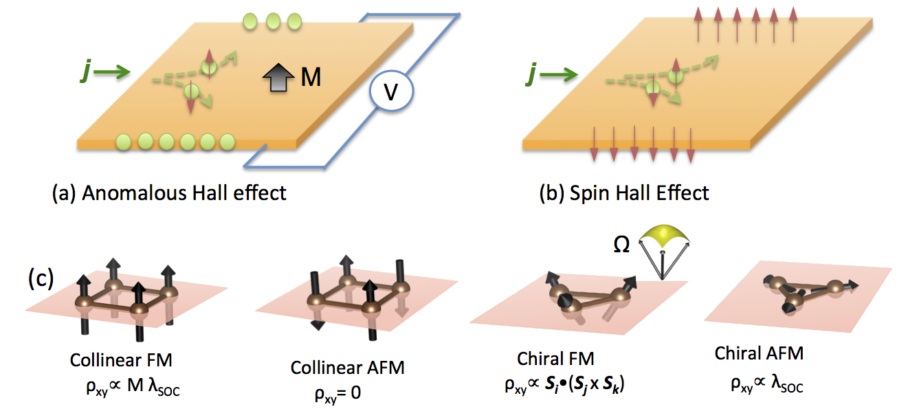
The AHE and SHE originate from the electronic and magnetic structures of materials and have both extrinsic and intrinsic origins. Extrinsic contributions depend sensitively on impurity scattering while intrinsic effects are derived from properties of the band structure. It is the intrinsic AHE and SHE that are the subject of this article. For the AHE of an ordinary collinear ferromagnet, it has been established that the Berry curvature, a quantity closely determined by the band structure, acts as a fictitious magnetic field in momentum space, that is derived from the magnetization and SOC, and affects the charge motion in the same way as a real magnetic field Xiao et al. (2010). In a collinear AFM, it is not surprising that the AHE vanishes due to the spin-up and -down conduction electron symmetry, or rather the existence of a symmetry by combining a time-reversal symmetry operation and a lattice translation. In a chiral ferromagnet where magnetic moments are tilted in a lattice, it was recently found that the aforementioned fictitious magnetic field can also be generated by the scalar spin chirality Ohgushi et al. (2000); Taguchi et al. (2001), ( denote three non-coplanar spins), which does not necessarily involve SOC. When an electron makes a loop trajectory in a chiral FM lattice, the electron acquires a real-space Berry phase due to double exchange interactions with the chiral lattice spins. The corresponding AHE has been referred to as a so-called real-space topological Hall effect in the literature (e.g. Neubauer et al. (2009)). In a chiral AFM in which the magnetic moments are coplanar, the topological Hall effect disappears because of the zero spin chirality. However, an AHE can still exist due to a nonzero Berry curvature induced by the SOC Chen et al. (2014). Indeed, a strong AHE was recently observed in the chiral AFM compounds Mn3Sn and Mn3Ge Chen et al. (2014); Kübler and Felser (2014); Nakatsuji et al. (2015); Nayak et al. (2016). In principle, the SHE exists generically in systems with strong SOC. It has been studied
in nonmagnetic Guo et al. (2008); Tanaka et al. (2008); Freimuth et al. (2010); Zimmermann et al. (2014) as well as antiferromagnetic Zimmermann et al. (2014); Fukami et al. (2016); Oh et al. (2016); Tshitoyan et al. (2015); Zhang et al. (2014) metals. Very recently, a strong SHE was experimentally discovered in another chiral AFM compound Mn3Ir Zhang et al. (2016). Therefore, chiral AFM materials are appealing candidates for finding significant AHE and SHE. They have also stimulated the search for Weyl points in the same family of materials Yang et al. (2016) and exotic magneto-optical Kerr effect Feng et al. (2015).
In this work, we have performed a comprehensive study of the intrinsic AHE and SHE of the compounds Mn ( Ge, Sn, Ga, Ir, Rh and Pt), using ab initio Berry phase calculations. These compounds exhibit a chiral AFM order well above room temperature (see Table I). This article is organized as follows. We first introduce the ab initio method and the linear-response method that we have used to compute the AHE and SHE in Sec. II. We then discuss the relationship of the symmetry of the crystal lattice and magnetic lattice to the SHC and AHC in Sec. III. In Sec. IV, we discuss the results of our calculations with the assistance of symmetry analysis, where the Mn compounds are classified into two groups according to their crystal and magnetic structures. Finally, we summarize our results in Sec. V.
II methods
The anomalous Hall conductivity (AHC) and spin Hall conductivity (SHC) characterize the AHE and SHE, respectively. In addition, the spin lifetime and related spin manipulation methods are important ingredients for the SHE device applications, but these aspects are beyond the scope of the current study. The AHC and SHC have been calculated using the Berry phase that we have determined from ab initio band structures. Density-functional theory (DFT) calculations were performed for the Mn3X bulk crystals with the Vienna Simulation Package (vasp) Kresse and Furthmüller (1996) within the generalized gradient approximation (GGA) Perdew et al. (1996). The SOC was included in our calculations. The material-specific Hamiltonians were established by projecting the DFT Bloch wave functions onto maximally localized Wannier functions (MLWFs) Mostofi et al. (2008). Based on these tight-binding Hamiltonians, that include realistic material parameters, we have calculated the intrinsic AHC and SHC by using the Kubo formula approach within the linear response Xiao et al. (2010); Nagaosa et al. (2010); Sinova et al. (2015); Gradhand et al. (2012). The AHC () is obtained from
| (1) | |||
where is the velocity operator with ; is the position operator. is the Fermi-Dirac distribution. and are the eigenvector and eigenvalue of the Hamiltonian , respectively. is the Berry curvature in momentum space, and the corresponding AHC can be evaluated by summing the Berry curvature over the Brillouin zone (BZ) for all the occupied bands. Here corresponds to a matrix and indicates a transverse Hall current generated by a longitudinal electric field , which satisfies . For the evaluation of the velocity operator we assume for simplicity that the position operator is diagonal in the Wannier basis, as is commonly done in tight-binding calculations.
The intrinsic SHC can be obtained by replacing the velocity operator with the spin current operator , where is the spin operator. The SHC then has the form of
| (2) | |||
is referred to as the spin Berry curvature in the following, in order to distinguish it from the Berry curvature . The SHC (; ) is a third-order tensor () and represents the spin current generated by an electric field via , where flows along the -direction with the spin-polarization along the direction and is the component of the electric field .
For the integrals of Eqns. 1-2, the BZ was sampled by -grids from to . Satisfactory convergence was achieved for a -grid of size . Increasing the grid size to varied the SHC and AHC by no more than 5%. Note that the unit of SHC differs from that of the AHC by , where is the spin angular momentum and is the electron charge. Thus, the unit of SHC is .
Since AHC and SHC are determined directly by the band structure, they are fully compatible with the symmetry of the Hamiltonian. Therefore, we can use symmetry analysis to simplify the shape of the AHC and SHC tensor matrices, by forcing certain matrix elements to be zero and constraining some to be the same. Here, we obtain the shape of the intrinsic response tensor from the Linear-Response-Symmetry code Železný et al. (2017); sym , which analyzes the symmetry operations of the corresponding crystal and magnetic space groups iso and then determines the tensor shape by solving the linear equations. We note that a similar study Seemann et al. (2015) also recently considered how the shape of the tensor response varied according to the magnetic Laue group. The shape of the AHC and SHC tensors are shown in Table II. These are very helpful in checking the validity and numerical convergence of our calculations by comparing the symmetry of the calculated matrices and the ideal symmetry-imposed matrices. Furthermore, the tensor shape surely relies on the coordinate system that is specified in the next section. The AHC and SHC tensors can be expressed in different coordinate systems, which are physically equivalent, and can be transformed into each other according to specific rotation matrices Kleiner (1966).
III Crystallographic and magnetic structures
The compounds considered here can be classified into two groups according to their crystallographic structure. Mn3Ga, Mn3Ge and Mn3Sn display an hexagonal lattice with the space group (No. 194). The primitive unit cell includes two Mn planes that are stacked along the axis according to “–AB–AB–”. Each structure contains plane of Mn atoms that constitute a Kagome-type lattice with Ga, Ge or Sn lying at the center of a hexagon formed from the Mn atoms. In the Kagome plane due to magneto-geometrical frustration, the Mn magnetic moments exhibit a non-collinear AFM order, where the neighboring moments are aligned at a 120∘ angle Krén and Kádár (1970); Kádár and Krén (1971); Ohoyama et al. (1961). The energetically favored AFM configuration was revealed, as illustrated in Fig. 2a, in earlier DFT calculations Zhang et al. (2013). The magnetic ordering temperatures are above 365 K for all these three compounds, as shown in Table I. Additionally, Mn3Ga and Mn3Ge can also crystallize into a tetragonal phase with a ferrimagnetic structure Krén and Kádár (1970); Kádár and Krén (1971); Balke et al. (2007), which is not considered in this work.
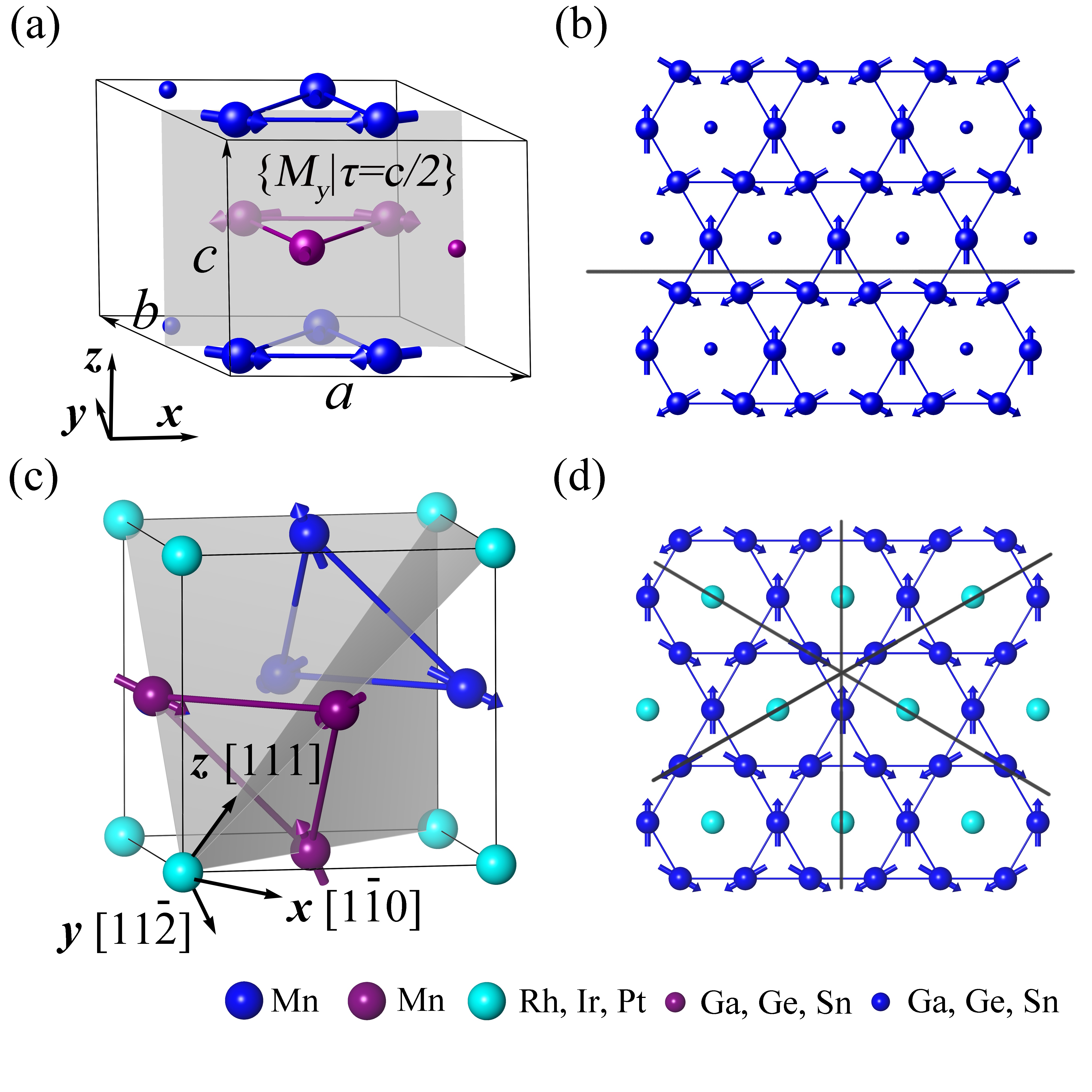
Mn3Rh, Mn3Ir and Mn3Pt crystallize in a face-centered cubic (FCC) lattice (space group , No. 221) with Ir (Rh, Pt) and Mn located at the corner and face-center sites, respectively, as shown in Fig. 2b. Within the (111) plane, the Mn sublattice also form a Kagome lattice. In contrast to that of Mn3Ge, the Kagome planes stack in an “–ABC–ABC–” sequence. The non-collinear AFM structure has also been observed by neutron diffraction measurements Krén et al. (1968); Tomeno et al. (1999); Krén et al. (1966). Distinct from Mn3Ge, here the magnetic moments all point towards or away from the center of the Mn triangles. The AFM order also persists to well above room temperature. (see Table I).
| Crystal | Magnetic | ||
| (K) | space group | space group | |
| Mn3Gaa | 470 | , no. 194 | |
| Mn3Geb | 365 | ||
| Mn3Snc | 420 | ||
| Mn3Rhd | , no. 221 | ||
| Mn3Ire | |||
| Mn3Ptf | |||
| , Ref. Krén and Kádár,1970 | , Ref. Yamada et al.,1988 | , Ref. Sticht et al.,1989 | |
| , Ref. Krén et al.,1966 | , Ref. Tomeno et al.,1999 | , Refs. Krén et al.,1966, 1968 |
IV Results and Discussions
IV.1 Anomalous Hall Effect in Mn3Ga, Mn3Ge and Mn3Sn
The AHC can be understood by a consideration of the symmetry of the magnetic structure. As indicated in Fig. 1a there is a mirror plane that is parallel to the plane. By combining a mirror reflection about this plane and a translation operation along the direction , the system is imaged back onto itself with the same crystallographic and magnetic structures. Therefore, the magnetic structure in Mn3Ga, Mn3Ge and Mn3Sn is symmetric with respect to the symmetry operator. The mirror operation changes the signs of and , but preserves , since is a pseudovector, just like the spin. Accordingly, and that are parallel to the mirror plane are transformed to and , with respect to the reflection (the translation operation does not affect the Berry curvature). Thus, from symmetry considerations, and must be zero, and only can be nonzero. We therefore propose that the preferred experimental setup for maximizing AHC is to confine the electric field within the plane, for example, by setting the electric current along and detecting the transverse voltage along .
| AHC | SHC | |||||
|---|---|---|---|---|---|---|
|
||||||
|
||||||
|
||||||
|
||||||
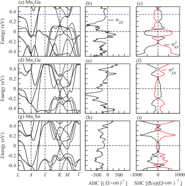
Our calculations are fully consistent with the above symmetry analysis, as shown in Table II, where only () is nonzero. The AHC of Mn3Ge is as large as 330 . Although Mn3Sn has a stronger SOC than Mn3Ge, its AHC is less than half that of Mn3Ge. Mn3Ga exhibits the smallest AHC and, moreover, the AHC has the opposite sign to those of the Ge and Sn compounds. This is fully consistent with recent experiments on the Ge and Sn compounds Nakatsuji et al. (2015); Nayak et al. (2016), where the in-plane AHC () is negligible compared to the out-of-plane AHC ( and ), and Mn3Sn displays a smaller AHC in magnitude than Mn3Ge. We note that and may be both nonzero if a different coordinate axis is chosen or the chiral moments are rotated by an external magnetic field.
Since the intrinsic AHE originates from the electronic band structure, we analyzed the band structure in detail to understand the differences among these three compounds. Their calculated band structures are shown in Fig. 3. Since the valence electrons for Ga and Ge (Sn) are and (), respectively, the band structure of Mn3Ga looks very similar to that of Mn3Ge (Mn3Sn). The Fermi level is shifted up by 0.34 eV (equivalent to adding one electron). Correspondingly, the shapes of the energy-dependent AHC curves for Mn3Ga and Mn3Ge (Mn3Sn) are also very similar. The value of in Mn3Ga changes sign from negative to positive after tuning up the Fermi level.
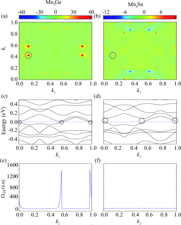
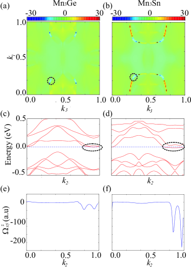
Atomic Ge and Sn have similar valence electron configurations while Sn has a larger atomic radius and stronger SOC compared to Ge. Although the consequent changes in the band structures are subtle (see Fig. 3), the effect on the resultant AHC can be significant. To better understand the AHE in Mn3Ge and Mn3Sn, we considered the distributions of the Berry curvature in the reciprocal space. We have projected the Berry curvature components of onto the - (-) plane by integrating them along , where are the reciprocal lattice vectors, and and are aligned with the and axes, respectively. The projected Berry curvatures of Mn3Ge and Mn3Sn with the Fermi level lying at the charge neutral point are shown in Figs. 4(a) and 4(b), respectively. One can easily identify the origin of the significant differences of the Berry curvature between Mn3Ge and Mn3Sn. The large AHC mainly arises from the positive located around (0.127, 0.428) (the coordinates are in units of the reciprocal lattice vectors and ) and its three partners in the - plane, while these four hot spots are not seen in Mn3Sn. Taking the hotspot at (0.127, 0.428) as an example, we have checked the band structure and corresponding Berry curvature evolution with varying from 0 to 1. From the band structure of Mn3Ge in Fig. 4(c) we can see that the Fermi level crosses two small gaps around =0 and 0.5. According to Eqn. 1, the entanglement between occupied and unoccupied states must be very strong around these two points and contributes to a large Berry curvatures, as indicated by the two peaks in Fig. 4(e). This is fully consistent with previous calculations on Mn3Ge Nayak et al. (2016). Mn3Sn has a similar band structure along the same -path, as can be seen by comparing Fig. 4(c) and (d), whereas the band gaps around =0 and 0.5 are much larger compared to that in Mn3Ge. Consequently, the two Berry curvature peaks disappear in Mn3Sn, as shown in Fig. 4(f). Thus, a tiny changes in band structure can result in significant changes in the Berry curvature and AHC in this class of compounds.
IV.2 Spin Hall Effect in Mn3Ga, Mn3Ge and Mn3Sn
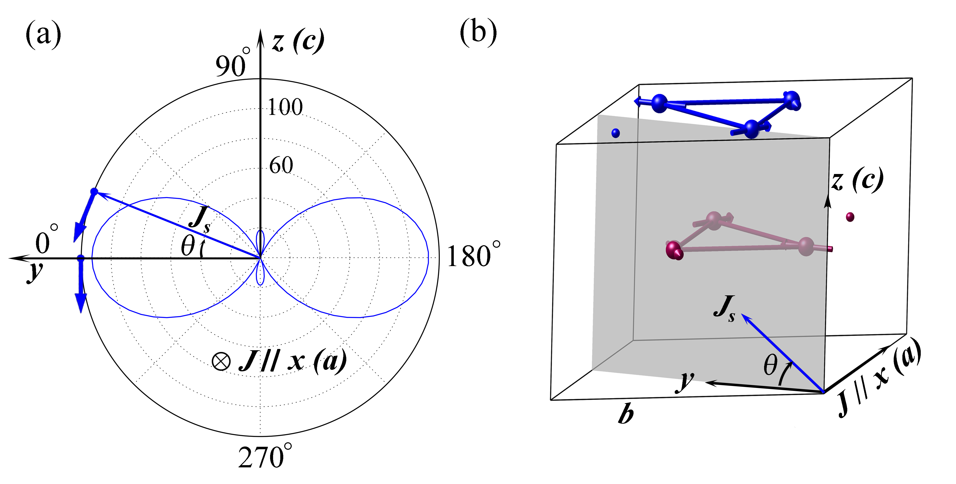
By adding the spin degree of freedom, the SHC becomes a third-order tensor. Similar to the AHC, some SHC tensor elements will be exactly zero or will be identical based on the corresponding lattice and magnetic symmetries. The magnetic space group for Mn (=Ga, Ge and Sn) is identified to be and the corresponding Laue group is iso . The calculated shape of the intrinsic SHC tensor and corresponding numerical results are presented in Table II. Furthermore, the SHC of Mn (=Ga, Ge and Sn) is strongly anisotropic with dominant components of and . These results will provides helpful information for the experimental detection of the SHE. To illustrate the anisotropy of the SHC, we show the angle-dependent SHC for Mn3Ge in Fig. 5. When the charge current is fixed along -axis ( direction) and by considering the spin current perpendicular to and rotating it, the corresponding magnitude of SHC is maximal for while being zero for . Therefore, to observe large SHC, one should set the charge current and spin current inside the Kagome () plane, for example with the electron current set along and by measuring the transverse spin current along with its spin polarization along . Therefore, we stress that for optimizing the efficiency of devices that rely on SHE and AHE, the direction of the charge current and the resulting spin current will depend on the respective compound.
As shown in Table II, the largest SHCs and are of the order of 120 in magnitude for Mn3Ge. With the relatively small electrical conductivity (about 3300 ), we would have a spin Hall angle up to . Also the elements in Mn3Ga is around 600 . Additionally, it is not surprising that and are not equal in magnitude, for the and directions are not equivalent in a Kagome structure.
Since the SHC is strongly related to the location of the Fermi level, the SHC varies quickly as the Fermi energy is shifted, especially for the metallic band structures shown in Fig. 3. The energy-dependent SHC of the most prominent tensor elements and for the three compounds are shown in Figs. 3 (e), (f) and (i). Owing to the similar crystal lattice constant and the same magnetic order, the shapes of the SHC curves are very similar, if we ignore the fact that Ga has one electron less than either Ge or Sn. For Mn3Ga, the SHC exhibits a minimum at the Fermi level, the charge neutral point, and increases quickly if the Fermi level moves up or down. Hence an even larger SHC is expected for Mn3Ga with small electron or hole doping. One can see that the SHC remains relatively stable with respect to varying the Fermi level in the energy window of 0.1 eV for Mn3Ge and Mn3Sn. Thus indicates that the SHC in the Ge and Sn compounds is robust.
Since the spin Berry curvature is distinct from the Berry curvature, the SHC and AHC can have dominant contributions from different electronic bands. Although Mn3Ge and Mn3Sn display very different AHCs in magnitude, their SHCs are very close. Therefore, we expect a similar spin Berry curvature distribution in space for both compounds. Taking the components of as an example, we compare the spin Berry curvature distributions for Mn3Ge and Mn3Sn with the Fermi energy lying at the charge neutral point. Similar to the above analysis for the AHE, we also project the spin Berry curvature onto the plane by integrating along . As shown in Fig. 6, Mn3Ge and Mn3Sn display similar features in their respective spin Berry curvature distributions. The shapes of the dominant areas are very similar in both compounds, with just a little shift within the plane. The dominant contribution forms thick arcs with a transition point between positive and negative amplitudes, where the integrated spin Berry curvature transfers from positive to negative. Since the size of the positive dominant area is much larger than that of the negative part, the integral of the spin Berry curvature in the whole BZ gives a positive SHC , as is listed in Table II.
The above positive-negative spin Berry curvature distribution is reminiscent of the similar feature of the SHE around Weyl point, where positive and negative spin Berry curvature appear with the Weyl point as the transition point Yang et al. (2016). In fact Weyl points also exist in Mn3Ge and Mn3Sn, however, the spin Berry curvature transition point in Fig. 6 does not exactly overlap with the Weyl point. A careful inspection of the band dispersions along through these hot spots reveals tiny band gaps that contribute to the peaks of the spin Berry curvature, as shown in Figs. 6 (e) and (f). Therefore, the intrinsic SHC mainly arises from the small band gaps lying very close to the Fermi level.
IV.3 Anomalous Hall effect and spin Hall effect in Mn3Rh, Mn3Ir and Mn3Pt
| AHC | SHC | |||||
|---|---|---|---|---|---|---|
|
||||||
|
||||||
|
||||||
|
||||||
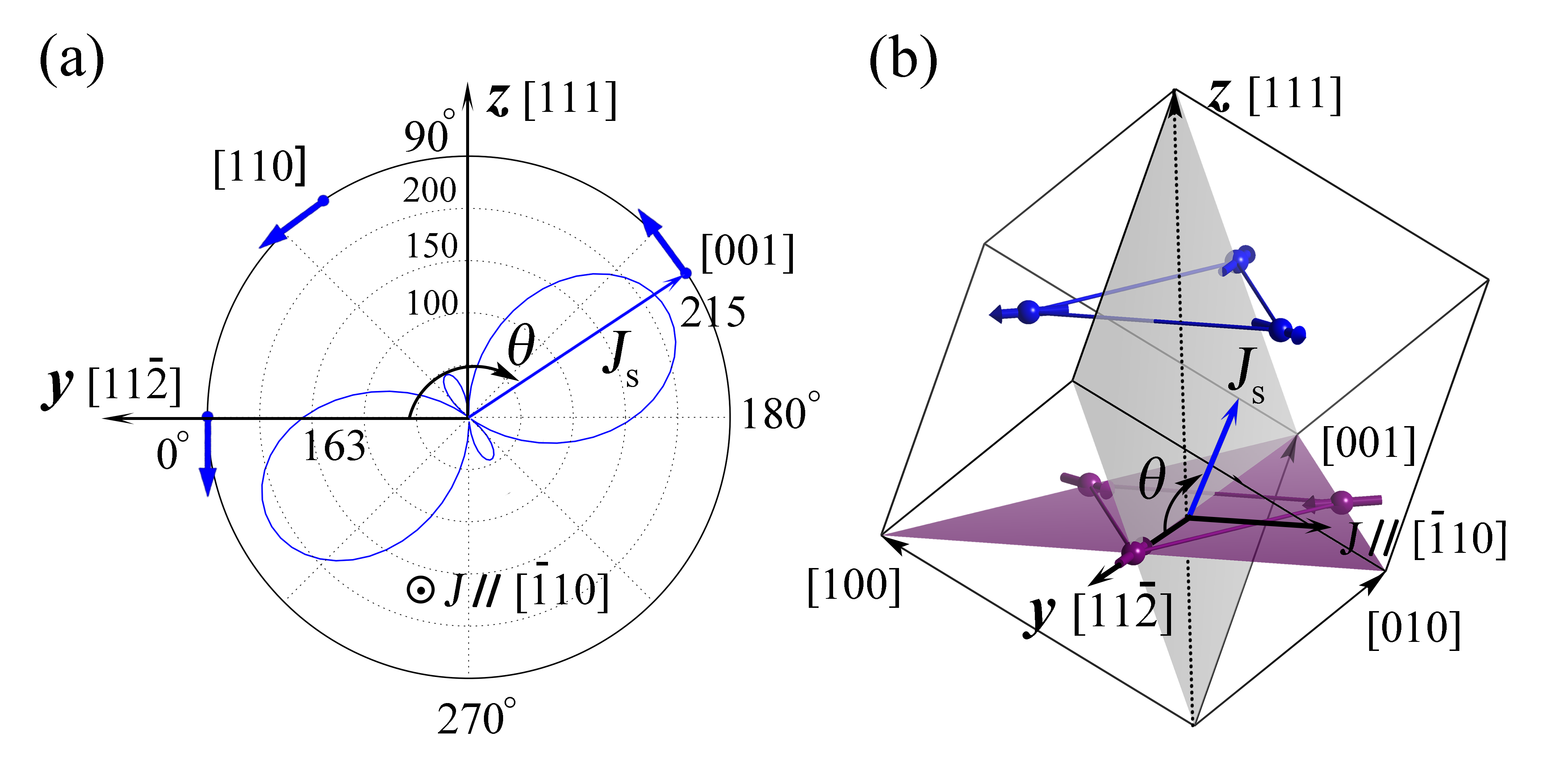
In the cubic lattice of Mn3Rh, Mn3Ir and Mn3Pt, there are three mirror planes that intersect the crystallographic [111] axis and which are related to each other by a three-fold rotation. The mirror reflection preserves the lattice symmetry but reverses all spins in the Kagome plane. Since time-reversal symmetry can also reverse spins, the combined symmetry of time-reversal and mirror symmetry, is the symmetry of the system. forces the out-of-mirror-plane AHC components to be zero, since the out-of-plane Berry curvature is odd with respect to but even with respect to . Given the existence of the three mirror planes, the only nonzero AHC component is along the co-axis of these three planes, i.e. the [111] axis. For the convenience of the symmetry analysis, we used coordinates with along the [111] direction and , within the Kagome plane (see Fig. 1).
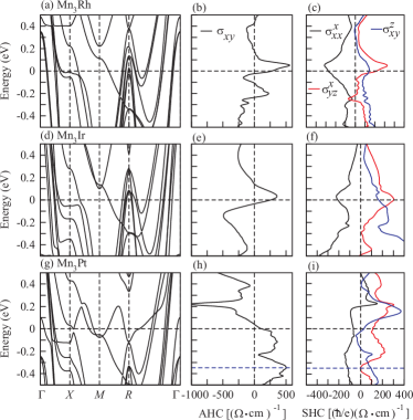
Our numerical calculations are again consistent with the symmetry analysis. The AHC for Mn3Ir can reach with the electric field lying in the (111) plane, as presented in Table III, which agrees with previous calculations Chen et al. (2014). Compared to Mn3Ir, Mn3Rh exhibits similar AHC in magnitude while Mn3Pt shows a much smaller AHC. Mn3Rh and Mn3Ir show very similar trends in the Fermi-energy-dependent AHC, as shown in Figs. 7(b) and (e). The peak values appear around 50 meV above the charge neutral point for both Mn3Rh and Mn3Ir. Therefore, in order to get strong AHE, one simply needs weak electron doping, and the AHC in the (111) plane can then reach 450 and 500 for Mn3Rh and Mn3Ir, respectively. Compared to Rh and Ir, Pt has one more valence electron. Hence the Mn3Pt can be viewed as a strongly doped version of Mn3Ir, which shifts the Fermi level a little further beyond the peak values, leading to a small AHC of 98 , as shown in Fig. 7(h).
The magnetic space group for Rh, Ir and Pt compounds is , from which we can obtain the symmetry of the SHC tensor. As shown in Table III, there are only four independent nonzero elements. Our numerical calculations fit the symmetry-imposed tensor shape very well, as shown in Table III. The largest SHC tensor elements are () and (===) for Mn3Rh and Mn3Ir. Therefore, the optimal experimental arrangement for large SHC is to align within the plane [the (111) Kagome plane]. It is interesting that , and the spin polarization of are not necessarily perpendicular to each other and even can be parallel, as indicated by the nonzero . The large value of shows a longitudinal spin current induced by a charge current along the same direction. Such a longitudinal spin current is common in FM metals where conduction electrons are naturally spin-polarized. However, it is interesting that these three AFM compounds can generate a similar spin current, which may promise novel spintronic applications. In previous experiments on Mn3Ir Zhang et al. (2016), the spin current was measured in two cases where the charge current was fixed along the [] crystallographic direction (i.e. axis of the current work), along the [111] (i.e. axis) direction and the [001] direction. The former case was found to exhibit a much smaller SHE than the latter one. Therefore, we calculate the angle-dependent SHC by fixing and rotating in the plane for Mn3Ir, as shown in Fig. 8. One clearly sees that the SHC is only 7 for the former case () and 215 for the latter case ().
Similar to the AHC, the peak values of and also appear around 50 meV above the charge neutral point for Mn3Rh and Mn3Ir, while their is quite small. In contrast, the Fermi-energy-dependent AHC of Mn3Pt shows a similar shape to that of the Rh and Ir compounds but the corresponding Fermi energy should be upshifted by one additional electron, as shown in Fig. 7(i). Thus, it is not surprising that shows a large magnitude at the charge neutral point for Mn3Pt.
V Summary
| AHE | SHE | |
|---|---|---|
| Mn3Ga | plane | plane |
| Mn3Ge | ||
| Mn3Sn | ||
| Mn3Rh | plane | inside the plane |
| Mn3Ir | ||
| Mn3Pt |
In summary, we have studied the intrinsic AHE and SHE in the non-collinear AFM compounds Mn (Ge, Sn, Ga, Rh, Ir, and Pt) by calculations. Large AHC and large SHC are found for these materials, which are also highly anisotropic and in agreement with recent experimental measurements. Such an anisotropy is closely related to the symmetry of the AFM Kagome lattice, which can be helpful in rationalizing the numerical results. Based on our calculations, we have proposed the optimal experimental setups to maximize the AHE and SHE for different systems, as shown in Table IV. Although the SOC magnitude increases from Rh, to Ir and to Pt, the magnitude of the corresponding AHC and SHC do not follow the same trend. This is also true for the Ga, Ge, and Sn compounds. This indicates that the electron filling and the detailed band structures are essential in determining the magnitude of the AHE and SHE. We point out that the largest SHC attains a value of around 600 in Mn3Ga. Our work provides insights in the interpretation and realization of a strong AHE and SHE in chiral AFM materials.
Acknowledgements.
We thank Jario Sinova, Jereon van den Brink, and Carsten Timm for helpful discussions. C.F. acknowledges the funding support by ERC (Advanced Grant No. 291472 ”Idea Heusler”). Y.Z. and B.Y. acknowledge the German Research Foundation (DFG) SFB 1143.References
- Nagaosa et al. (2010) N. Nagaosa, J. Sinova, S. Onoda, A. H. MacDonald, and N. P. Ong, Reviews of Modern Physics 82, 1539 (2010).
- Sinova et al. (2015) J. Sinova, S. O. Valenzuela, J. Wunderlich, C. Back, and T. Jungwirth, Reviews of Modern Physics 87 (2015).
- Dyakonov and Perel (1971) M. Dyakonov and V. Perel, Physics Letters A 35, 459 (1971).
- Jungwirth et al. (2012) T. Jungwirth, J. Wunderlich, and K. Olejník, Nature Materials 11, 382 (2012).
- Maekawa et al. (2012) S. Maekawa, S. O. Valenzuela, E. Saitoh, and T. Kimura, Spin Current, Vol. 17 (Oxford University Press, 2012).
- Hoffmann (2013) A. Hoffmann, IEEE TRANSACTIONS ON MAGNETICS 49, 5172 (2013).
- Parkin and Yang (2015) S. Parkin and S.-H. Yang, Nature Nanotech 10, 195 (2015).
- Yang et al. (2015) S.-H. Yang, K.-S. Ryu, and S. Parkin, Nature Nanotech 10, 221 (2015).
- Xiao et al. (2010) D. Xiao, M.-C. Chang, and Q. Niu, Rev. Mod. Phys. 82, 1959 (2010).
- Ohgushi et al. (2000) K. Ohgushi, S. Murakami, and N. Nagaosa, Physical Review B 62, R6065 (2000).
- Taguchi et al. (2001) Y. Taguchi, Y. Oohara, H. Yoshizawa, N. Nagaosa, and Y. Tokura, Science 291, 2573 (2001).
- Neubauer et al. (2009) A. Neubauer, C. Pfleiderer, B. Binz, A. Rosch, R. Ritz, P. G. Niklowitz, and P. Böni, Phys. Rev. Lett. 102, 186602 (2009).
- Chen et al. (2014) H. Chen, Q. Niu, and A. MacDonald, Phys. Rev. Lett. 112, 017205 (2014).
- Kübler and Felser (2014) J. Kübler and C. Felser, EPL 108, 67001 (2014).
- Nakatsuji et al. (2015) S. Nakatsuji, N. Kiyohara, and T. Higo, Nature 527, 212 (2015).
- Nayak et al. (2016) A. K. Nayak, J. E. Fischer, Y. Sun, B. Yan, J. Karel, A. C. Komarek, C. Shekhar, N. Kumar, W. Schnelle, J. Kuebler, C. Felser, and S. S. P. Parkin, Science Advances 2, 150187 (2016).
- Guo et al. (2008) G. Y. Guo, S. Murakami, T.-W. Chen, and N. Nagaosa, Phys. Rev. Lett. 100, 096401 (2008).
- Tanaka et al. (2008) T. Tanaka, H. Kontani, M. Naito, T. Naito, D. S. Hirashima, K. Yamada, and J. Inoue, Phys. Rev. B 77, 165117 (2008).
- Freimuth et al. (2010) F. Freimuth, S. Blügel, and Y. Mokrousov, Phys. Rev. Lett. 105, 246602 (2010).
- Zimmermann et al. (2014) B. Zimmermann, K. Chadova, D. Kodderitzsch, S. Blügel, H. Ebert, D. V. Fedorov, N. H. Long, P. Mavropoulos, I. Mertig, Y. Mokrousov, and M. Gradhand, Phys. Rev. B 90, 220403 (2014).
- Fukami et al. (2016) S. Fukami, C. Zhang, S. DuttaGupta, A. Kurenkov, and H. Ohno, Nature materials (2016).
- Oh et al. (2016) Y.-W. Oh, S.-h. C. Baek, Y. Kim, H. Y. Lee, K.-D. Lee, C.-G. Yang, E.-S. Park, K.-S. Lee, K.-W. Kim, G. Go, et al., Nature Nanotechnology (2016).
- Tshitoyan et al. (2015) V. Tshitoyan, C. Ciccarelli, A. Mihai, M. Ali, A. Irvine, T. Moore, T. Jungwirth, and A. Ferguson, Physical Review B 92, 214406 (2015).
- Zhang et al. (2014) W. Zhang, M. B. Jungfleisch, W. Jiang, J. E. Pearson, A. Hoffmann, F. Freimuth, and Y. Mokrousov, Physical review letters 113, 196602 (2014).
- Zhang et al. (2016) W. Zhang, W. Han, S. H. Yang, Y. Sun, Y. Zhang, B. Yan, and S. Parkin, Science Advances 2, e1600759 (2016).
- Yang et al. (2016) H. Yang, Y. Sun, Y. Zhang, W.-J. Shi, S. S. P. Parkin, and B. Yan, arXiv:1608.03404 (2016).
- Feng et al. (2015) W. Feng, G.-Y. Guo, J. Zhou, Y. Yao, and Q. Niu, Phys. Rev. B 92, 144426 (2015).
- Kresse and Furthmüller (1996) G. Kresse and J. Furthmüller, Phys. Rev. B 54, 11169 (1996).
- Perdew et al. (1996) J. P. Perdew, K. Burke, and M. Ernzerhof, Phys. Rev. Lett. 77, 3865 (1996).
- Mostofi et al. (2008) A. A. Mostofi, J. R. Yates, Y.-S. Lee, I. Souza, D. Vanderbilt, and N. Marzari, Comput. Phys. Commun. 178, 685 (2008).
- Gradhand et al. (2012) M. Gradhand, D. Fedorov, F. Pientka, P. Zahn, I. Mertig, and B. L. Györffy, Journal of Physics: Condensed Matter 24, 213202 (2012).
- Železný et al. (2017) J. Železný, H. Gao, A. Manchon, F. Freimuth, Y. Mokrousov, J. Zemen, J. Mašek, J. Sinova, and T. Jungwirth, Phys. Rev. B 95, 014403 (2017).
- (33) https://bitbucket.org/zeleznyj/linear-response-symmetry.
- (34) ISOTROPY Software Suite, iso.byu.edu.
- Seemann et al. (2015) M. Seemann, D. Koedderitzsch, S. Wimmer, and H. Ebert, Physical Review B 92, 155138 (2015).
- Kleiner (1966) W. H. Kleiner, Physical Review 142 (1966).
- Krén and Kádár (1970) E. Krén and G. Kádár, Solid State Communications 8, 1653 (1970).
- Kádár and Krén (1971) G. Kádár and E. Krén, International Journal of Magnetism 1, 43 (1971).
- Ohoyama et al. (1961) T. Ohoyama, K. Yasuköchi, and K. Kanematsu, Phys. Soc. Japan 16, 325 (1961).
- Zhang et al. (2013) D. Zhang, B. Yan, S.-C. Wu, J. Kübler, G. Kreiner, S. S. Parkin, and C. Felser, Journal of Physics: Condensed Matter 25, 206006 (2013).
- Balke et al. (2007) B. Balke, G. H. Fecher, J. Winterlik, and C. Felser, Appl. Phys. Lett. 90, 152504 (2007).
- Krén et al. (1968) E. Krén, G. Kádár, L. Pál, J. Sólyom, P. Szabó, and T. Tarnóczi, Physical review 171, 574 (1968).
- Tomeno et al. (1999) I. Tomeno, H. N. Fuke, H. Iwasaki, M. Sahashi, and Y. Tsunoda, Journal of applied physics 86, 3853 (1999).
- Krén et al. (1966) E. Krén, G. Kádár, L. Pál, J. Sólyom, and P. Szabó, Physics Letters 20, 331 (1966).
- Yamada et al. (1988) N. Yamada, H. Sakai, H. Mori, and T. Ohoyama, Physica B+ C 149, 311 (1988).
- Sticht et al. (1989) J. Sticht, K. Höck, and J. Kübler, Journal of Physics: Condensed Matter 1, 8155 (1989).